


Filter by
Switching Voltage
Switch Action
Actuator Style


Illumination
Switch Starting Position
Push-Button Shape

Hazardous Location Rating
U.S.–Mexico–Canada Agreement (USMCA) Qualifying
Export Control Classification Number (ECCN)
DFARS Specialty Metals

About Electrical Switches
Choose a switch with the right trigger type, number of inputs, and control functions to power your equipment.
Hazardous Location 22 mm Panel-Mount Push-Button Switches
 |  |  |  |
Black Switch | Green Switch | White Switch | Red Switch |
 |  |  | |
Illuminated Green Switch | Illuminated White Switch | Illuminated Red Switch |
No. of Circuits Controlled | Switch Starting Position | Switch Action | No. of Terminals | Switch Designation | Switching Current @ Voltage | Dia. | For Max. Panel Thk. | Dp. Behind Panel | For Max. No. of Contact Blocks | Bulb Voltage | Actuator Color | Enclosure Rating | Each | |||
|---|---|---|---|---|---|---|---|---|---|---|---|---|---|---|---|---|
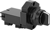
Metal Actuator Base with Screw-Terminal Wire Connection—Not Illuminated (600V AC/300V DC Maximum Voltage) | ||||||||||||||||
Flush | ||||||||||||||||
| 1 | 1 Off | Momentary | 3 | SPST-NO | 6 amp @ 120V AC, 2.8 amp @ 24V DC | 1 3/16" | 0.24" | 2 1/4" | 6 | — | Black | IP66, NEMA 4X, NEMA 13 | 8022N11 | 000000 | ||
| 1 | 1 Off | Momentary | 3 | SPST-NO | 6 amp @ 120V AC, 2.8 amp @ 24V DC | 1 3/16" | 0.24" | 2 1/4" | 6 | — | Green | IP66, NEMA 4X, NEMA 13 | 8022N12 | 00000 | ||
| 1 | 1 Off | Momentary | 3 | SPST-NO | 6 amp @ 120V AC, 2.8 amp @ 24V DC | 1 3/16" | 0.24" | 2 1/4" | 6 | — | White | IP66, NEMA 4X, NEMA 13 | 8022N14 | 000000 | ||
| 1 | 1 On | Momentary | 3 | SPST-NC | 6 amp @ 120V AC, 2.8 amp @ 24V DC | 1 3/16" | 0.24" | 2 1/4" | 6 | — | Red | IP66, NEMA 4X, NEMA 13 | 8022N13 | 000000 | ||
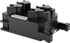
Metal Actuator Base with Screw-Terminal Wire Connection—Illuminated (600V AC/300V DC Maximum Voltage) | ||||||||||||||||
Flush | ||||||||||||||||
| 1 | 1 Off | Momentary | 3 | SPST-NO | 6 amp @ 120V AC, 2.8 amp @ 24V DC | 1 1/8" | 0.24" | 2 1/4" | 6 | 24V AC/24V DC | Green | IP66, NEMA 4X, NEMA 13 | 8022N15 | 000000 | ||
| 1 | 1 Off | Momentary | 3 | SPST-NO | 6 amp @ 120V AC, 2.8 amp @ 24V DC | 1 1/8" | 0.24" | 2 1/4" | 6 | 24V AC/24V DC | White | IP66, NEMA 4X, NEMA 13 | 8022N17 | 000000 | ||
| 1 | 1 On | Momentary | 3 | SPST-NC | 6 amp @ 120V AC, 2.8 amp @ 24V DC | 1 1/8" | 0.24" | 2 1/4" | 6 | 24V AC/24V DC | Red | IP66, NEMA 4X, NEMA 13 | 8022N16 | 000000 | ||
 |
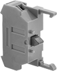
Additional contact blocks can be added to control more circuits, or replace the included contact block.
No. of Circuits Controlled | Switch Starting Position | No. of Terminals | Switch Designation | Switching Current @ Voltage | Max. Voltage | Wire Connection | Each | ||
|---|---|---|---|---|---|---|---|---|---|
| 1 | 1 Off | 3 | SPST-NO | 6 amp @ 120V AC, 2.8 amp @ 24V DC | 600V AC/300V DC | Screw Terminal | 8022N18 | 000000 | |
| 1 | 1 On | 3 | SPST-NC | 6 amp @ 120V AC, 2.8 amp @ 24V DC | 600V AC/300V DC | Screw Terminal | 8022N19 | 00000 |
Hazardous Location 30 mm Panel-Mount Lever Switches
 |
Made for areas where ignitable gas and vapor may be present, these switches have a housing that seals in anything that could spark flammable material. You'll know they're safe because they're NEC Class 1, Division 2, Groups A, B, C, and D certified for hazardous locations. They're also UL and C-UL listed and CSA certified. They require you to grip and twist a lever to turn them on or off, so they won’t accidentally actuate if you bump into them. Mount into a standard panel cutout.
Actuator Color | Lever Lg. | No. of Circuits Controlled | Switch Starting Position | Switch Action | No. of Terminals | Switch Designation | Switching Current @ Voltage | Max. Voltage | Dia. | Dp. Behind Panel | For Max. No. of Contact Blocks | Enclosure Rating | Each | |||
|---|---|---|---|---|---|---|---|---|---|---|---|---|---|---|---|---|
2 Positions | ||||||||||||||||
Screw-Terminal Wire Connection | ||||||||||||||||
| Black | 1 1/16" | 1 | 1 Off | Momentary | 2 | SPST-NO | 1.5 amp @ 120V AC, 0.55 amp @ 125V DC | 600V AC 300V DC | 1 3/8" | 3 1/16" | 2 | IP65 | 6982N13 | 0000000 | ||
| Black | 1 1/16" | 1 | 1 Off | Maintained | 2 | SPST-NO | 1.5 amp @ 120V AC, 0.55 amp @ 125V DC | 600V AC 300V DC | 1 3/8" | 3 1/16" | 2 | IP65 | 6982N14 | 000000 | ||
| Black | 1 1/16" | 1 | 1 On | Momentary | 2 | SPST-NC | 1.5 amp @ 120V AC, 0.55 amp @ 125V DC | 600V AC 300V DC | 1 3/8" | 3 1/16" | 2 | IP65 | 6982N21 | 000000 | ||
| Black | 1 1/16" | 1 | 1 On | Maintained | 2 | SPST-NC | 1.5 amp @ 120V AC, 0.55 amp @ 125V DC | 600V AC 300V DC | 1 3/8" | 3 1/16" | 2 | IP65 | 6982N22 | 000000 | ||
| Black | 1 1/16" | 2 | 1 Off and 1 On | Maintained | 4 | DPST-1NO/1NC | 6 amp @ 120V AC, 1.1 amp @ 125V DC | 600V AC 300V DC | 1 3/8" | 3 1/16" | 2 | IP65 | 6982N11 | 000000 | ||
3 Positions | ||||||||||||||||
Screw-Terminal Wire Connection | ||||||||||||||||
| Black | 1 1/16" | 2 | 2 Off | Maintained | 4 | DPST-NO | 1.5 amp @ 120V AC, 0.55 amp @ 125V DC | 600V AC 300V DC | 1 3/8" | 3 1/16" | 2 | IP65 | 6982N15 | 000000 | ||
| Black | 1 1/16" | 2 | 1 Off and 1 On | Maintained | 4 | DPST-1NO/1NC | 6 amp @ 120V AC, 1.1 amp @ 125V DC | 600V AC 300V DC | 1 3/8" | 3 1/16" | 2 | IP65 | 6982N12 | 000000 | ||
 |
Additional contact blocks can be added to control more circuits, or to replace the included contact block.
No. of Circuits Controlled | Switch Starting Position | No. of Terminals | Switch Designation | Enclosure Rating | Certification | Each | ||
|---|---|---|---|---|---|---|---|---|
| 1 | 1 Off | 2 | SPST-NO | IP65 | UL Listed, UL Recognized Component, C-UL Listed, CSA Certified, CE Marked | 6982N17 | 000000 | |
| 1 | 1 On | 2 | SPST-NC | IP65 | UL Listed, UL Recognized Component, C-UL Listed, CSA Certified, CE Marked | 6982N18 | 00000 | |
| 2 | 1 Off and 1 On | 4 | DPST-1NO/1NC | IP65 | UL Listed, UL Recognized Component, C-UL Listed, CSA Certified, CE Marked | 6982N16 | 000000 | |
| 2 | 2 Off | 4 | DPST-NO | IP65 | UL Listed, UL Recognized Component, C-UL Listed, CSA Certified, CE Marked | 6982N23 | 000000 |
Aluminum Enclosed Push-Button Switches
Screw-Terminal Wire Connection
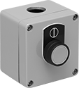 | 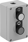 | 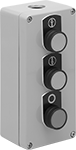 |
One Button | Two Buttons | Three Buttons |
 |  |
Circle | Vertical Line |
 |  |
Up Arrow | Down Arrow |
Actuator Color (Switch Designation) | No. of Circuits Controlled per Button | Switch Starting Position | Switch Action | No. of Terminals per Button | Switching Current @ Voltage | Max. Voltage | Conduit Trade Size | Enclosure Rating | Hazardous Location Rating | Each | |||
|---|---|---|---|---|---|---|---|---|---|---|---|---|---|
1 Button | |||||||||||||
| Green with Vertical Line (SPST-NO) | 1 | 1 Off | Momentary | 2 | 10 amp @ 120V AC, 4 amp @ 24V DC | 600V AC 600V DC | 1/2 | IP66, IP67, NEMA 4X, NEMA 13 | ATEX II 1 GD Ex Ia IIC T6-T3 Ga Ex Ta IIIC T85°C-T180°C Da; ATEX II 2 GD Ex E IIC T6-T3 Gb Ex Tb IIIC T85°C-T180°C Db; Ex E IIC; IEC Zone 0 Groups IIC, IIB, IIA; IEC Zone 20 Groups IIIC, IIIB, IIIA; IECEx Ex E IIC T6-T3 Gb Ex Tb IIIC T85°C-T180°C Db; IECEx Ex Ia IIC T6-T3 Ga Ex Ta IIIC T85°C-T180°C Da; NEC Class I Division 2 Groups A, B, C, D; NEC Zone 1 Groups IIC, IIB, IIA | 6156K41 | 0000000 | ||
| Red with Circle (SPST-NC) | 1 | 1 On | Momentary | 2 | 10 amp @ 120V AC, 4 amp @ 24V DC | 600V AC 600V DC | 1/2 | IP66, IP67, NEMA 4X, NEMA 13 | ATEX II 1 GD Ex Ia IIC T6-T3 Ga Ex Ta IIIC T85°C-T180°C Da; ATEX II 2 GD Ex E IIC T6-T3 Gb Ex Tb IIIC T85°C-T180°C Db; Ex E IIC; IEC Zone 0 Groups IIC, IIB, IIA; IEC Zone 20 Groups IIIC, IIIB, IIIA; IECEx Ex E IIC T6-T3 Gb Ex Tb IIIC T85°C-T180°C Db; IECEx Ex Ia IIC T6-T3 Ga Ex Ta IIIC T85°C-T180°C Da; NEC Class I Division 2 Groups A, B, C, D; NEC Zone 1 Groups IIC, IIB, IIA | 6156K42 | 000000 | ||
2 Buttons | |||||||||||||
| Green with Vertical Line (SPST-NO) Red with Circle (SPST-NC) | 1 | 1 Off | Momentary | 2 | 10 amp @ 120V AC, 4 amp @ 24V DC | 600V AC 600V DC | 1/2 | IP66, IP67, NEMA 4X, NEMA 13 | ATEX II 1 GD Ex Ia IIC T6-T3 Ga Ex Ta IIIC T85°C-T180°C Da; ATEX II 2 GD Ex E IIC T6-T3 Gb Ex Tb IIIC T85°C-T180°C Db; Ex E IIC; IEC Zone 0 Groups IIC, IIB, IIA; IEC Zone 20 Groups IIIC, IIIB, IIIA; IECEx Ex E IIC T6-T3 Gb Ex Tb IIIC T85°C-T180°C Db; IECEx Ex Ia IIC T6-T3 Ga Ex Ta IIIC T85°C-T180°C Da; NEC Class I Division 2 Groups A, B, C, D; NEC Zone 1 Groups IIC, IIB, IIA | 6156K45 | 000000 | ||
3 Buttons | |||||||||||||
| Green with Up Arrow (SPST-NO) Red with Circle (SPST-NC) Green with Down Arrow (SPST-NO) | 1 | 1 Off | Momentary | 2 | 10 amp @ 120V AC, 4 amp @ 24V DC | 600V AC 600V DC | 1/2 | IP66, IP67, NEMA 4X, NEMA 13 | ATEX II 1 GD Ex Ia IIC T6-T3 Ga Ex Ta IIIC T85°C-T180°C Da; ATEX II 2 GD Ex E IIC T6-T3 Gb Ex Tb IIIC T85°C-T180°C Db; Ex E IIC; IEC Zone 0 Groups IIC, IIB, IIA; IEC Zone 20 Groups IIIC, IIIB, IIIA; IECEx Ex E IIC T6-T3 Gb Ex Tb IIIC T85°C-T180°C Db; IECEx Ex Ia IIC T6-T3 Ga Ex Ta IIIC T85°C-T180°C Da; NEC Class I Division 2 Groups A, B, C, D; NEC Zone 1 Groups IIC, IIB, IIA | 6156K46 | 000000 | ||
Circuit Board Magnetically Actuated Switches
Plastic Housing
Switches with a plastic housing withstand impact better than switches with a glass housing. The plastic also forms an airtight seal to block out contaminants. Use them in dusty or dirty environments where an optical switch might fail.
No. of Circuits Controlled | Switch Starting Position | Switch Designation | Switching Current @ Voltage | Max. Voltage, V DC | Wire Dia. | Lg. | Wd. | Ht. | Hazardous Location Protection Type | Hazardous Location Rating | Certification | Includes | Pkg. Qty. | Pkg. | ||
|---|---|---|---|---|---|---|---|---|---|---|---|---|---|---|---|---|
| 1 | 1 Off | SPST-NO | 0.5 amp @ 200V DC | 250 | 0.02" | 0.6" | 0.1" | 0.1" | Hermetically Sealed | NEC Class I Division 2 Groups A, B, C, D | UL Recognized Component, C-UL Recognized Component | Magnet | 20 | 8307N11 | 000000 |
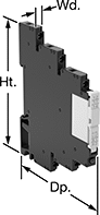
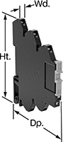
Hazardous Location Relays
 |  |  |
Screw Terminals | Spring-Clamp Terminals | Circular-Pin Terminals—Hermetically Sealed |
 |  | |
Quick-Disconnect Terminals—Hermetically Sealed | Sockets with Screw Terminals |
Sealed for safety, these relays are a good choice for hazardous locations where combustible or corrosive gases may be present.
Screw Terminals—Relays with screw terminals are considered interface relays, so they’re placed between your controller and components to isolate the input and output circuits. This means they protect your component from voltage spikes while amplifying the relay’s signal and reducing interference for reliable transmission. They are often used for switching applications, such as small motors and pilot lights. The included relay socket mounts on 35 mm DIN rail (also known as DIN 3 rail).
Spring-Clamp Terminals—Relays with spring-clamp terminals are considered interface relays, so they’re placed between your controller and components to isolate the input and output circuits. This means they protect your component from voltage spikes while amplifying the relay’s signal and reducing interference for reliable transmission. They are often used for switching applications, such as small motors and pilot lights. The included relay socket mounts on 35 mm DIN rail (also known as DIN 3 rail). Relays with spring-clamp terminals connect and disconnect to wires without needing to turn screws. With no screws to shake loose with vibration, the terminals hold tight over time.
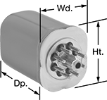
Circular-Pin Terminal and Quick-Disconnect Terminal—Relays with circular-pin terminals or quick-disconnect terminals are hermetically sealed—completely air- and watertight—to shield internal parts from gases, moisture, and other contaminants. They plug into relay sockets (sold separately) for easy installation.
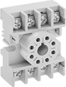
Sockets with Screw Terminals—Relay sockets mount to 35 mm DIN rail (also known as DIN 3 rail) or flat surfaces.
Relays | Sockets with Screw Terminals | ||||||||||||||||
|---|---|---|---|---|---|---|---|---|---|---|---|---|---|---|---|---|---|
No. of Terminals | Input Voltage | Control Current, mA | Switching Current @ Voltage | Max. Switching Voltage | hp @ Switching Voltage | Ht. | Wd. | Dp. | Quick-Disconnect Tab Wd. | Enclosure Rating | Hazardous Location Rating | Each | Each | ||||
Screw Terminals | |||||||||||||||||
1 Circuit Controlled with 1 Off or 1 On—SPDT | |||||||||||||||||
| 5 | 12V AC, 12V DC | 15.5 | 6 amp @ 240V AC/30V DC | 400V AC/125V DC | — | 2.9" | 0.2" | 3.5" | — | IP20 | NEC Class I Division 2 Groups A, B, C, D | 4190N311 | 000000 | ——— | 0 | ||
| 5 | 12V AC, 12V DC | 29 | 12 amp @ 240V AC/24V DC | 400V AC/300V DC | — | 2.9" | 0.6" | 3.5" | — | IP20 | NEC Class I Division 2 Groups A, B, C, D | 4190N312 | 00000 | ——— | 0 | ||
| 5 | 24V AC, 24V DC | 13.5 | 6 amp @ 240V AC/30V DC | 400V AC/125V DC | — | 3.5" | 0.2" | 2.9" | — | IP20 | NEC Class I Division 2 Groups A, B, C, D | 4190N11 | 00000 | ——— | 0 | ||
| 5 | 24V AC, 24V DC | 13.5 | 16 amp @ 240V AC/24V DC | 400V AC/300V DC | — | 3.5" | 0.6" | 2.9" | — | IP20 | NEC Class I Division 2 Groups A, B, C, D | 4190N15 | 00000 | ——— | 0 | ||
| 5 | 48V AC, 48V DC | 4 | 6 amp @ 240V AC/30V DC | 400V AC/125V DC | — | 3.5" | 0.2" | 2.9" | — | IP20 | NEC Class I Division 2 Groups A, B, C, D | 4190N12 | 00000 | ——— | 0 | ||
| 5 | 48V AC, 48V DC | 4 | 16 amp @ 240V AC/24V DC | 400V AC/300V DC | — | 3.5" | 0.6" | 2.9" | — | IP20 | NEC Class I Division 2 Groups A, B, C, D | 4190N17 | 00000 | ——— | 0 | ||
| 5 | 120V AC, 120V DC | 3.5 | 6 amp @ 240V AC/30V DC | 400V AC/125V DC | — | 3.5" | 0.2" | 2.9" | — | IP20 | NEC Class I Division 2 Groups A, B, C, D | 4190N13 | 00000 | ——— | 0 | ||
| 5 | 120V AC, 120V DC | 3.5 | 16 amp @ 240V AC/24V DC | 400V AC/300V DC | — | 3.5" | 0.6" | 2.9" | — | IP20 | NEC Class I Division 2 Groups A, B, C, D | 4190N19 | 00000 | ——— | 0 | ||
| 5 | 240V AC, 240V DC | 3.5 | 6 amp @ 240V AC/30V DC | 400V AC/125V DC | — | 3.5" | 0.2" | 2.9" | — | IP20 | NEC Class I Division 2 Groups A, B, C, D | 4190N14 | 00000 | ——— | 0 | ||
| 5 | 240V AC, 240V DC | 3.5 | 16 amp @ 240V AC/24V DC | 400V AC/300V DC | — | 3.5" | 0.6" | 2.9" | — | IP20 | NEC Class I Division 2 Groups A, B, C, D | 4190N22 | 00000 | ——— | 0 | ||
2 Circuits Controlled with 2 Off or 2 On—DPDT | |||||||||||||||||
| 8 | 24V AC, 24V DC | 13.5 | 8 amp @ 240V AC/24V DC | 400V AC/300V DC | — | 3.5" | 0.6" | 2.9" | — | IP20 | NEC Class I Division 2 Groups A, B, C, D | 4190N16 | 00000 | ——— | 0 | ||
| 8 | 48V AC, 48V DC | 4 | 8 amp @ 240V AC/24V DC | 400V AC/300V DC | — | 3.5" | 0.6" | 2.9" | — | IP20 | NEC Class I Division 2 Groups A, B, C, D | 4190N18 | 00000 | ——— | 0 | ||
| 8 | 120V AC, 120V DC | 3.5 | 8 amp @ 240V AC/24V DC | 400V AC/300V DC | — | 3.5" | 0.6" | 2.9" | — | IP20 | NEC Class I Division 2 Groups A, B, C, D | 4190N21 | 00000 | ——— | 0 | ||
| 8 | 240V AC, 240V DC | 3.5 | 8 amp @ 240V AC/24V DC | 400V AC/300V DC | — | 3.5" | 0.6" | 2.9" | — | IP20 | NEC Class I Division 2 Groups A, B, C, D | 4190N23 | 00000 | ——— | 0 | ||
Spring-Clamp Terminals | |||||||||||||||||
1 Circuit Controlled with 1 Off or 1 On—SPDT | |||||||||||||||||
| 5 | 12V AC, 12V DC | 15.5 | 6 amp @ 240V AC/30V DC | 400V AC/125V DC | — | 2.9" | 0.2" | 3.7" | — | IP20 | NEC Class I Division 2 Groups A, B, C, D | 8163N11 | 00000 | ——— | 0 | ||
| 5 | 12V AC, 12V DC | 29 | 12 amp @ 240V AC/24V DC | 400V AC/300V DC | — | 2.9" | 0.6" | 3.7" | — | IP20 | NEC Class I Division 2 Groups A, B, C, D | 8163N14 | 00000 | ——— | 0 | ||
| 5 | 24V AC, 24V DC | 13.5 | 6 amp @ 240V AC/30V DC | 400V AC/125V DC | — | 2.9" | 0.2" | 3.7" | — | IP20 | NEC Class I Division 2 Groups A, B, C, D | 8163N12 | 00000 | ——— | 0 | ||
| 5 | 24V AC, 24V DC | 20 | 12 amp @ 240V AC/24V DC | 400V AC/300V DC | — | 2.9" | 0.6" | 3.7" | — | IP20 | NEC Class I Division 2 Groups A, B, C, D | 8163N15 | 00000 | ——— | 0 | ||
| 5 | 120V AC, 120V DC | 3.5 | 6 amp @ 240V AC/30V DC | 400V AC/125V DC | — | 2.9" | 0.2" | 3.7" | — | IP20 | NEC Class I Division 2 Groups A, B, C, D | 8163N13 | 00000 | ——— | 0 | ||
| 5 | 120V AC, 120V DC | 4 | 12 amp @ 240V AC/24V DC | 400V AC/300V DC | — | 2.9" | 0.6" | 3.7" | — | IP20 | NEC Class I Division 2 Groups A, B, C, D | 8163N16 | 00000 | ——— | 0 | ||
Circular-Pin Terminals—Hermetically Sealed | |||||||||||||||||
2 Circuits Controlled with 2 Off or 2 On—DPDT | |||||||||||||||||
| 8 | 120V AC | 10 | 12 amp @ 120V AC/24V DC | 300V AC | 1/3 hp @ 120V AC | 1.6" | 1.4" | 2.1" | — | — | NEC Class I Division 2 Groups A, B, C, D | 7125T32 | 000000 | 7125T41 | 00000 | ||
| 8 | 24V DC | 38 | 12 amp @ 120V AC/24V DC | 300V AC | 1/3 hp @ 120V AC | 1.6" | 1.4" | 2.1" | — | — | NEC Class I Division 2 Groups A, B, C, D | 7125T34 | 000000 | 7125T41 | 0000 | ||
3 Circuits Controlled with 3 Off or 3 On—3PDT | |||||||||||||||||
| 11 | 120V AC | 100 | 12 amp @ 120V AC/240V AC | 300V AC | 1/3 hp @ 120V AC | 1.6" | 1.4" | 2.1" | — | — | NEC Class I Division 2 Groups A, B, C, D | 7125T111 | 000000 | 7122K21 | 0000 | ||
Quick-Disconnect Terminals—Hermetically Sealed | |||||||||||||||||
4 Circuits Controlled with 4 Off or 4 On—4PDT | |||||||||||||||||
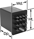
| 14 | 120V AC | 100 | 3 amp @ 120V AC/240V AC | 240V AC | 1/10 hp @ 120V AC | 1.2" | 0.9" | 1.3" | 0.125" | — | NEC Class I Division 2 Groups A, B, C, D | 8161N11 | 000000 | 7122K25 | 00000 | ||
Differential Pressure Switches with Dial Indicator for Liquids
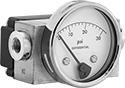 |
To check the difference in pressure between two points, these switches have a dial indicator that shows differential pressure in real time. The dial indicator operates independently of the switch. You’ll sometimes see these switches used to indicate a filter is clogged in a pump or cooling system. When the differential pressure reaches your setpoint, they turn equipment on and off, activate automated controls, or signal alarms. They are single pole, double throw (SPDT) and can be installed to turn one circuit from off to on or from on to off.
Rated NEMA 4X, these switches protect against dirt, washdown, and corrosion. They are also rated IP65 for protection from dust and rinsing. All are CSA certified, so they meet Canadian safety standards.
Pressure Set Point | Approx. Difference Between Set Point and Reset Point | Max. Input Pressure, psi | Accuracy | Max. Switching Current @ Voltage | Process Temp. Range, ° F | Connection Material | For Use With | Certification | Enclosure Rating | Hazardous Location Rating | Each | |||
|---|---|---|---|---|---|---|---|---|---|---|---|---|---|---|
Screw-Terminal Wire Connection | ||||||||||||||
1/4 NPT Female Pipe Connection | ||||||||||||||
| 0 in. H₂O to 25 in. H₂O | 5 in. H₂O | 1,500 | ±2% | 250 mA @ 120V AC | -20 to 175 | Brass | Cleaning Solutions, Diesel Fuel, Gasoline, Hydraulic Fluid, Oil, Water | CSA Certified | IP65, NEMA 4X | NEC Class I Division 2 Groups A, B, C, D; NEC Class II Division 2 Groups F, G | 4587N11 | 0000000 | ||
| 0 psi to 1 psi | 0.2 psi | 1,500 | ±2% | 250 mA @ 120V AC | -20 to 175 | Brass | Cleaning Solutions, Diesel Fuel, Gasoline, Hydraulic Fluid, Oil, Water | CSA Certified | IP65, NEMA 4X | NEC Class I Division 2 Groups A, B, C, D; NEC Class II Division 2 Groups F, G | 4587N12 | 000000 | ||
| 0 psi to 5 psi | 1 psi | 1,500 | ±2% | 250 mA @ 120V AC | -20 to 175 | Brass | Cleaning Solutions, Diesel Fuel, Gasoline, Hydraulic Fluid, Oil, Water | CSA Certified | IP65, NEMA 4X | NEC Class I Division 2 Groups A, B, C, D; NEC Class II Division 2 Groups F, G | 4587N13 | 000000 | ||
| 3 psi to 15 psi | 3 psi | 5,000 | ±2% | 250 mA @ 120V AC | -40 to 175 | Brass | Cleaning Solutions, Diesel Fuel, Gasoline, Hydraulic Fluid, Oil, Water | CSA Certified | IP65, NEMA 4X | NEC Class I Division 2 Groups A, B, C, D; NEC Class II Division 2 Groups F, G | 40945K81 | 000000 | ||
| 6 psi to 30 psi | 6 psi | 5,000 | ±2% | 250 mA @ 120V AC | -40 to 175 | Brass | Cleaning Solutions, Diesel Fuel, Gasoline, Hydraulic Fluid, Oil, Water | CSA Certified | IP65, NEMA 4X | NEC Class I Division 2 Groups A, B, C, D; NEC Class II Division 2 Groups F, G | 40945K82 | 000000 | ||
| 10 psi to 50 psi | 10 psi | 5,000 | ±2% | 250 mA @ 120V AC | -40 to 175 | Brass | Cleaning Solutions, Diesel Fuel, Gasoline, Hydraulic Fluid, Oil, Water | CSA Certified | IP65, NEMA 4X | NEC Class I Division 2 Groups A, B, C, D; NEC Class II Division 2 Groups F, G | 40945K83 | 000000 | ||
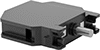
Hazardous Location 30 mm Panel-Mount Key Switches
 |
Designed for use near ignitable gases, fibers, and dust, these switches have a housing that seals in anything that could ignite flammable material. You’ll know they’re safe because they’re NEC Class 1, Division 2 Groups A-D and NEC Zone 1 Groups IIC-IIA certified for hazardous locations. These switches require a key to turn circuits on or off, preventing accidental actuation and limiting access to sensitive equipment. Since they’re keyed alike, all open with the same key. Install them in a standard panel cutout.
2 Circuits Controlled—Switches that control two circuits come with a contact block for each circuit.
No. of Circuits Controlled | Switch Starting Position | Switch Action | No. of Terminals | Switch Designation | Switching Current @ Voltage | Max. Voltage | Dia. | Dp. Behind Panel | For Max. No. of Contact Blocks | No. of Keys Included | Key Removal Position | Enclosure Rating | Each | |||
|---|---|---|---|---|---|---|---|---|---|---|---|---|---|---|---|---|
2 Positions with Plastic Actuator Base | ||||||||||||||||
Keyed Alike with Screw-Terminal Wire Connection | ||||||||||||||||
| 1 | 1 Off | Momentary | 2 | SPST-NO | 6 amp @ 120V AC, 4 amp @ 24V DC | 500V AC 500V DC | 1 9/16" | 2 5/8" | 3 | 2 | Left | IP20 | 6914N13 | 0000000 | ||
| 1 | 1 Off | Maintained | 2 | SPST-NO | 6 amp @ 120V AC, 4 amp @ 24V DC | 500V AC 500V DC | 1 9/16" | 2 5/8" | 3 | 2 | Left, Right | IP20 | 6914N11 | 000000 | ||
| 1 | 1 On | Maintained | 2 | SPST-NC | 6 amp @ 120V AC, 4 amp @ 24V DC | 500V AC 500V DC | 1 9/16" | 2 5/8" | 3 | 2 | Left, Right | IP20 | 6914N12 | 000000 | ||
| 2 | 1 Off and 1 On | Maintained | 4 | DPST-1NO/1NC | 6 amp @ 120V AC, 4 amp @ 24V DC | 500V AC 500V DC | 1 9/16" | 2 5/8" | 3 | 2 | Left, Right | IP20 | 6914N14 | 000000 | ||
3 Positions with Plastic Actuator Base | ||||||||||||||||
Keyed Alike with Screw-Terminal Wire Connection | ||||||||||||||||
| 2 | 2 Off | Maintained | 4 | DPST-NO | 6 amp @ 120V AC, 4 amp @ 24V DC | 500V AC 500V DC | 1 9/16" | 2 5/8" | 3 | 2 | Center, Left, Right | IP20 | 6914N15 | 000000 | ||
 |
Additional contact blocks can be added to control more circuits, or to replace the included contact block.
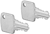 |
Key No. | Each | ||
|---|---|---|---|
| HW9Z-SKP | 6914N16 | 000000 |
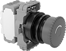
Hazardous Location 30 mm Panel-Mount Push-Button Switches
 |
Mushroom with Twist Reset |
Actuate these switches with a quick push. A housing seals in anything that could ignite flammable material, so you can use them where ignitable gas and dust may be present. You’ll know they’re safe because they meet NEC Class I Div. 2, Groups B, C, D for hazardous locations. Install them in a standard panel cutout.
Switches come with a contact block for each number of circuits they control.
Mushroom Push Button—Mushroom switches have a button that sticks out from the panel. Because they’re easy to identify and actuate, these switches are often used to stop equipment. They have a twist reset, so they’ll return to their starting position when you rotate the button.
No. of Circuits Controlled | Switch Starting Position | Switch Action | No. of Terminals | Switch Designation | Switching Current @ Voltage | Dia. | For Max. Panel Thk. | Dp. Behind Panel | For Max. No. of Contact Blocks | Actuator Color | Each | |||
|---|---|---|---|---|---|---|---|---|---|---|---|---|---|---|
Plastic Actuator Base with Screw-Terminal Wire Connection—Not Illuminated (690V AC/255V DC Maximum Voltage) | ||||||||||||||
Mushroom with Twist Reset | ||||||||||||||
| 1 | 1 Off or 1 On | Maintained | 3 | SPDT | 6 amp @ 120V AC, 1.1 amp @ 120V DC | 1 5/8" | 1/4" | 2 9/16" | 2 | Red | 6977N11 | 0000000 | ||
| 1 | 1 On | Maintained | 2 | SPST-NC | 6 amp @ 120V AC, 1.1 amp @ 120V DC | 1 5/8" | 1/4" | 2 9/16" | 2 | Red | 6977N13 | 000000 | ||
| 2 | 2 Off | Maintained | 4 | DPST-NO | 6 amp @ 120V AC, 1.1 amp @ 120V DC | 1 5/8" | 1/4" | 2 9/16" | 2 | Red | 6977N14 | 000000 | ||
| 2 | 2 On | Maintained | 4 | DPST-NC | 6 amp @ 120V AC, 1.1 amp @ 120V DC | 1 5/8" | 1/4" | 2 9/16" | 2 | Red | 6977N15 | 000000 | ||
 |
Contact Block |
Blocks—Additional contact blocks can be added to control more circuits, or replace the included contact block.
Mounting Bracket |
For Push-Button Style | Material | For Panel Cutout Dia. | Each | ||
|---|---|---|---|---|---|
| Mushroom | Plastic | 30 mm, 1 3/16" | 6977N17 | 000000 |
Hazardous Location HMIs
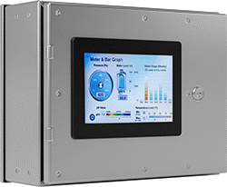 |
Shown Mounted (Enclosure Not Included) |
From chemical plants to refineries, these HMIs let you safely control and monitor equipment in areas where flammable and combustible gases, vapors, and liquids may escape from leaks or failures. They’re rated for use in NEC Class 1, Division 2 hazardous locations. Since they come with a touchscreen and software designed specifically to integrate with your PLC, you don’t need to spend time or money on the complex setup and extra equipment of industrial PCs.
The manufacturer’s free PC software guides you through communication setup and screen design using drag-and-drop tools. Preview your layout, test navigation, and catch design errors before you connect to any equipment. When you’re ready, transfer your setup to the HMI with a USB cord, memory card, or Ethernet cord.
All of our HMIs support the PLCs we currently offer, plus those from systems such as Allen-Bradley and Siemens.
When mounted in an enclosure, the front of these HMIs is NEMA 4X and IP rated for protection against dust and light washdowns.
All of these HMIs are compatible with RFID readers.
Pressure Activated Touchscreen
Diag. Screen Size | No. of Supported Communication Drivers | Screen Resolution | Max. Screen Brightness, cd/m² | Serial Port Interface (No. of) | Connection Type (No. of) | Memory Type (Size) | Features | Housing Material | Operating Temp. Range, ° F | Enclosure Rating | Hazardous Location Rating | Certification | Each | ||
|---|---|---|---|---|---|---|---|---|---|---|---|---|---|---|---|
| 7" | 440 | 1024 × 600 | 1,200 | RS-232 (1) RS-485/ CAN-Bus (1) | Ethernet RJ45 (2) USB-A (1) | Flash (4 GB) RAM (1 GB) | — | Aluminum | 0 to 130 | IP66 NEMA 4X | NEC Class I Division 2 Groups A, B, C, D | UL Listed C-UL Listed CE Marked | 8872N12 | 0000000 | |
| 10.1" | 440 | 1024 × 600 | 350 | RS-232 (1) RS-485/ CAN-Bus (1) | Ethernet RJ45 (2) USB-A (1) | Flash (4 GB) RAM (1 GB) | Built-In RFID Antenna | Plastic | 32 to 120 | IP66 NEMA 4X | ATEX II 3 G Ex Ec IIC T6 Gc ATEX II 3 G Ex Tc IIIB T80° C Dc IEC Zone 2 Groups IIC, IIB, IIA IEC Zone 22 Groups IIIB, IIIA NEC Class I Division 2 Groups A, B, C, D | UL Listed C-UL Listed CE Marked | 8872N13 | 00000000 | |
| 10.1" | 440 | 1280 × 800 | 500 | RS-232 (1) RS-485/ CAN-Bus (1) | Ethernet RJ45 (2) USB-A (1) | Flash (4 GB) RAM (1 GB) | Built-In Speaker | Plastic | 32 to 130 | IP66 NEMA 4X | ATEX II 3 G Ex Ec IIC T6 Gc ATEX II 3 G Ex Tc IIIB T80° C Dc IEC Zone 2 Groups IIC, IIB, IIA IEC Zone 22 Groups IIIB, IIIA NEC Class I Division 2 Groups A, B, C, D | UL Listed C-UL Listed CE Marked | 8872N14 | 00000000 |
Gesture Enabled Touchscreen
Diag. Screen Size | No. of Supported Communication Drivers | Screen Resolution | Max. Screen Brightness, cd/m² | Serial Port Interface (No. of) | Connection Type (No. of) | Memory Type (Size) | Features | Housing Material | Operating Temp. Range, ° F | Enclosure Rating | Hazardous Location Rating | Certification | Each | ||
|---|---|---|---|---|---|---|---|---|---|---|---|---|---|---|---|
| 7" | 50 | 800 × 480 | 1,000 | RS-232 (1) RS-422/ RS-485 (1) | Ethernet RJ45 (2) USB-A (1) Mini USB-B (1) Standard SD Card (1) 3.5 mm Audio Output (1) | Flash (8 GB) SDRAM (1 GB) | — | Aluminum | 0 to 145 | IP68 NEMA 4X | NEC Class I Division 2 Groups A, B, C, D | UL Listed C-UL Listed CE Marked | 8872N11 | 0000000 | |
| 10.1" | 440 | 1280 × 800 | 425 | RS-232 (1) RS-485/ CAN-Bus (1) | Ethernet RJ45 (2) USB-A (1) | Flash (4 GB) RAM (1 GB) | Built-In Speaker | Plastic | 32 to 130 | IP66 NEMA 4X | ATEX II 3 G Ex Ec IIC T6 Gc ATEX II 3 G Ex Tc IIIB T80° C Dc IEC Zone 2 Groups IIC, IIB, IIA IEC Zone 22 Groups IIIB, IIIA NEC Class I Division 2 Groups A, B, C, D | UL Listed C-UL Listed CE Marked | 8872N15 | 00000000 |
