Filter by
Actuator Style


Mounting Location
Wire Connection


Number of Terminals
Switch Action
Switch Starting Position

Switch Type

Number of Mounting Holes
Electrical Connection


Number of Circuits Controlled
Horsepower @ Switching Voltage
Export Control Classification Number (ECCN)
DFARS Specialty Metals
Harsh Environment Snap-Acting Switches
 |  |
Style A | Style B |
 | |
Style C |
Open and close circuits in a snap—even in harsh conditions. With a rubber-encased housing and stainless steel bracket, these switches handle high vibrations and resist corrosion. They’re rated IP68 for protection from dust and temporary submersion. Because they open and close circuits faster than other switches—reducing the time that contacts are near one another—they prevent contacts from sticking. They also minimize the chance of arcing, so electricity won’t jump across contacts. They’re often used as door-open indicators on enclosures or as an internal component in limit, pressure, and temperature switches.
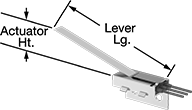
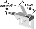
Lever Actuator Style—Lever actuator switches can be pushed down by front-to-back movement, so they can be activated with pressure anywhere along their length.
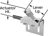
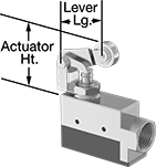
Roller Lever Actuator Style—Roller lever actuator switches activate when parts glide front-to-back across their actuation surface. They produce less friction than standard levers, which prevents wear and tear over time.
Simulated Roller Lever Actuator Style—Simulated roller lever actuator switches have a curved arm that can be pressed down for actuation by forward, backward, and repeated back-and-forth movement.
Wire Leads | Housing | ||||||||||||||||||
|---|---|---|---|---|---|---|---|---|---|---|---|---|---|---|---|---|---|---|---|
Style | No. of Circuits Controlled | Switch Starting Position | Switch Action | Switch Designation | Switching Current @ Voltage | Max. Voltage | Operating Temp. Range, ° F | Actuator Ht. | Wire Connection | No. of | Lg. | Lg. | Ht. | Dp. | Lever Lg. | Each | |||
Side Mount | |||||||||||||||||||
Lever Actuator Style | |||||||||||||||||||
| A | 1 | 1 Off | Momentary | SPST-NO | 5 amp @ 120V AC 5 amp @ 28V DC | 120V AC 28V DC | -40 to 185 | 1.04" | Wire Leads | 2 | 24" | 0.86" | 1.13" | 1.75" | 4.5" | 7287K102 | 0000000 | ||
| A | 1 | 1 Off or 1 On | Momentary | SPDT | 5 amp @ 120V AC 5 amp @ 28V DC | 120V AC 28V DC | -40 to 185 | 1.04" | Wire Leads | 3 | 24" | 0.86" | 1.13" | 1.75" | 4.5" | 7287K11 | 00000 | ||
Roller Lever Actuator Style | |||||||||||||||||||
| B | 1 | 1 Off | Momentary | SPST-NO | 5 amp @ 120V AC 5 amp @ 28V DC | 120V AC 28V DC | -40 to 185 | 0.81" | Wire Leads | 2 | 24" | 1" | 1.42" | 1.75" | 1.4" | 7287K103 | 000000 | ||
| B | 1 | 1 Off or 1 On | Momentary | SPDT | 5 amp @ 120V AC 5 amp @ 28V DC | 120V AC 28V DC | -40 to 185 | 0.81" | Wire Leads | 3 | 24" | 1" | 1.42" | 1.75" | 1.4" | 7287K12 | 00000 | ||
Simulated Roller Lever Actuator Style | |||||||||||||||||||
| C | 1 | 1 Off | Momentary | SPST-NO | 5 amp @ 120V AC 5 amp @ 28V DC | 120V AC 28V DC | -40 to 185 | 0.81" | Wire Leads | 2 | 24" | 1" | 1.42" | 1.75" | 1.3" | 7287K101 | 000000 | ||
| C | 1 | 1 Off or 1 On | Momentary | SPDT | 5 amp @ 120V AC 5 amp @ 28V DC | 120V AC 28V DC | -40 to 185 | 0.81" | Wire Leads | 3 | 24" | 1" | 1.42" | 1.75" | 1.3" | 7287K13 | 00000 | ||
Enclosed Snap-Acting Switches
 |  |  |
Style A | Style B | Style C |
 |  | |
Style D | Style E |
Housing | ||||||||||||||||||||
|---|---|---|---|---|---|---|---|---|---|---|---|---|---|---|---|---|---|---|---|---|
Style | No. of Circuits Controlled | Switch Starting Position | Switch Action | Switch Designation | Switching Current @ Voltage | Max. Voltage | hp @ Switching Voltage | Operating Temp. Range, ° F | Actuator Ht. | Wire Connection | No. of Terminals | Lg. | Ht. | Dp. | Conduit Trade Size | Lever Lg. | Each | |||
Side Mount | ||||||||||||||||||||
Plunger Actuator Style | ||||||||||||||||||||
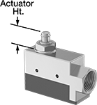
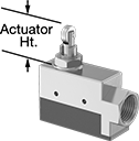
| A | 1 | 1 Off or 1 On | Momentary | SPDT | 15 amp @ 250V AC 0.5 amp @ 125V DC | 600V AC 250V DC | 1/4 hp @ 250V AC | -25 to 160 | 0.8" | Screw Terminal | 3 | 3.04" | 1.75" | 1" | 1/2 | — | 7778K13 | 000000 | ||
Roller Plunger Actuator Style | ||||||||||||||||||||
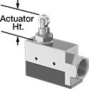
| B | 1 | 1 Off or 1 On | Momentary | SPDT | 15 amp @ 250V AC 0.5 amp @ 125V DC | 600V AC 250V DC | 1/4 hp @ 250V AC | -25 to 160 | 1.2" | Screw Terminal | 3 | 3.04" | 1.75" | 1" | 1/2 | — | 7778K14 | 000000 | ||
Lever Actuator Style | ||||||||||||||||||||
| C | 1 | 1 Off or 1 On | Momentary | SPDT | 15 amp @ 250V AC 0.5 amp @ 125V DC | 600V AC 250V DC | 1/4 hp @ 250V AC | -25 to 160 | 1.7" | Screw Terminal | 3 | 3.04" | 1.75" | 1" | 1/2 | 6" | 7778K17 | 000000 | ||
Roller Lever Actuator Style | ||||||||||||||||||||
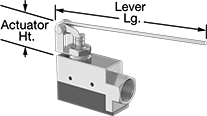
| D | 1 | 1 Off or 1 On | Momentary | SPDT | 15 amp @ 250V AC 0.5 amp @ 125V DC | 600V AC 250V DC | 1/4 hp @ 250V AC | -25 to 160 | 1.8" | Screw Terminal | 3 | 3.04" | 1.75" | 1" | 1/2 | 1.8" | 7778K16 | 000000 | ||
Cross Roller Plunger Actuator Style | ||||||||||||||||||||
| E | 1 | 1 Off or 1 On | Momentary | SPDT | 15 amp @ 250V AC 0.5 amp @ 125V DC | 600V AC 250V DC | 1/4 hp @ 250V AC | -25 to 160 | 1.2" | Screw Terminal | 3 | 3.04" | 1.75" | 1" | 1/2 | — | 7778K15 | 000000 | ||
Enclosed Washdown Snap-Acting Switches
 |  | 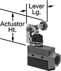 | 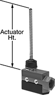 | 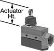 |
Style A | Style B | Style C | Style D | Style E |
Housing | ||||||||||||||||||||
|---|---|---|---|---|---|---|---|---|---|---|---|---|---|---|---|---|---|---|---|---|
Style | No. of Circuits Controlled | Switch Starting Position | Switch Action | Switch Designation | Switching Current @ Voltage | Max. Voltage | hp @ Switching Voltage | Operating Temp. Range, ° F | Actuator Ht. | Wire Connection | No. of Terminals | Lg. | Ht. | Dp. | Conduit Trade Size | Lever Lg. | Each | |||
Side Mount | ||||||||||||||||||||
Plunger Actuator Style | ||||||||||||||||||||
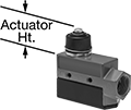
| A | 1 | 1 Off or 1 On | Momentary | SPDT | 15 amp @ 250V AC 0.5 amp @ 125V DC | 600V AC 250V DC | 1/4 hp @ 250V AC | -25 to 160 | 1" | Screw Terminal | 3 | 3.04" | 1.75" | 1" | 1/2 | — | 7778K66 | 0000000 | ||
Roller Plunger Actuator Style | ||||||||||||||||||||
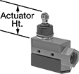
| B | 1 | 1 Off or 1 On | Momentary | SPDT | 15 amp @ 250V AC 0.5 amp @ 125V DC | 600V AC 250V DC | 1/4 hp @ 250V AC | -25 to 160 | 1.6" | Screw Terminal | 3 | 3.04" | 1.75" | 1" | 1/2 | — | 7778K68 | 000000 | ||
Roller Lever Actuator Style | ||||||||||||||||||||
| C | 1 | 1 Off or 1 On | Momentary | SPDT | 15 amp @ 250V AC 0.5 amp @ 125V DC | 600V AC 250V DC | 1/4 hp @ 250V AC | -25 to 160 | 2.3" | Screw Terminal | 3 | 3.04" | 1.75" | 1" | 1/2 | 1.8" | 7778K69 | 000000 | ||
Wobble Stick Actuator Style | ||||||||||||||||||||
| D | 1 | 1 Off or 1 On | Momentary | SPDT | 15 amp @ 250V AC 0.5 amp @ 125V DC | 600V AC 250V DC | 1/4 hp @ 250V AC | -25 to 160 | 5.1" | Screw Terminal | 3 | 3.04" | 1.75" | 1" | 1/2 | — | 7778K67 | 000000 | ||
Cross Roller Plunger Actuator Style | ||||||||||||||||||||
| E | 1 | 1 Off or 1 On | Momentary | SPDT | 15 amp @ 250V AC 0.5 amp @ 125V DC | 600V AC 250V DC | 1/4 hp @ 250V AC | -25 to 160 | 1.6" | Screw Terminal | 3 | 3.04" | 1.75" | 1" | 1/2 | — | 7778K12 | 000000 | ||
Paddle Level Switches for Dry Materials
 |
Horizontal Mount |
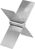
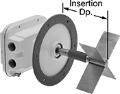
Monitor the level of dry material in surge bins, tanks, and silos to avoid overspills and outages. With a long paddle, these switches extend farther into large storage containers to detect material levels where other types of switches can’t reach. You can even adjust the paddle's sensitivity to materials of different sizes and shapes, such as powders, plastic pellets, and wood chips. Install multiple switches on the same container to monitor levels at various points. They are rated NEMA 4X and IP66 for protection from corrosion and washdowns.
Horizontal Mount—Commonly installed near the bottom of containers to indicate low levels as material flows out. These switches start to rotate when material falls low enough to uncover the paddle, triggering a conveyor, pump, or other piece of equipment to prevent the container from emptying.
With Alarm—Switches with an alarm alert you to potential malfunctions before they occur. They continuously perform self-diagnostics to detect everything from motor failure to seized bearings. When they detect an error, an LED light flashes in a corresponding code, so maintenance workers will immediately know which problem they need to fix.
Paddle | Switch | |||||||||||||||
|---|---|---|---|---|---|---|---|---|---|---|---|---|---|---|---|---|
Insertion Dp. | Material Wt. Cap. Range, lb/ft³ | Max. Pressure @ Temp. | Speed, rpm | Lg. | Wd. | Material | Starting Position | Designation | Current @ Voltage | Enclosure Rating | Hazardous Location Rating | Certification | Each | |||
Horizontal Mount | ||||||||||||||||
Without Alarm | ||||||||||||||||
| 6 5/8" | 0 to 30 | 30 psi @ 70° F | 1 | 7" | 2" | 316 Stainless Steel | 1 Off or 1 On | SPDT | 20 amp @ 120V AC | IP66 NEMA 4X | NEC Class I Divisions 1, 2 Groups C, D NEC Class II Divisions 1, 2 Groups E, F, G | UL Listed C-UL Listed | 49005K51 | 0000000 | ||
With Alarm | ||||||||||||||||
| 6 5/8" | 0 to 30 | 30 psi @ 70° F | 1 | 7" | 2" | 316 Stainless Steel | 1 Off or 1 On | SPDT | 8 amp @ 120V AC | IP66 NEMA 4X | NEC Class I Divisions 1, 2 Groups C, D NEC Class II Divisions 1, 2 Groups E, F, G | UL Listed C-UL Listed | 49005K26 | 000000 | ||