Choosing a Proximity Switch
More
Wide-Angle Safety Barrier Switches
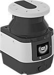
Scanning 275° side-to-side for people and objects, these switches (known as safety laser scanners) cover large areas and send signals to machinery to prevent accidents. Unlike other safety switches, which have a separate transmitter and receiver, these switches include the transmitter and receiver in a single unit. They trigger when light bounces off an object and back to the switch.
These switches respond to two types of areas: safety zones and warning zones. Safety zones act like traditional barrier switches—when a person or object enters the safety zone, they shut down machinery. When used with automatic guided vehicles (AGVs), the safety zone makes sure the vehicle has enough time to stop. Unlike other barrier switches, you can also add warning zones. Entering the warning zone triggers flashing lights, sirens, and other alarms, but doesn’t stop the machine. For AGVs, objects in the warning zone trigger reduced speed. Set up multiple warning zones to trigger escalating signals and precautions as the person or object gets closer to the machine. Switches with 10 or more zone settings let AGVs take more complex routes.
To program what areas to protect, what size objects they’ll detect, configure inputs and outputs, and view data, these switches come with their own software. This includes a muting feature, so you can program them to allow specific materials to pass through the scanning field without triggering a shut down. All have PNP output, so they communicate by sending a positive signal. They also have four LED status indicators and a digital display with push-button controls.
Rated IP65, these switches can be hosed down. They’re UL and C-UL listed, CE marked, and TUV certified, so they meet U.S. and international safety standards. They also meet EN, ISO, and IEC standards for performance and safety.
When choosing a switch, consider how much area you need to cover and how many machines you want to control. Independent switches monitor up to 275° of a single area. For more coverage, use master switches with up to three remote switches. This system can monitor a full circle around a large machine or a long space, such as the area along a conveyor. Connect remote switches to each other and to the master switch using remote switch cables. The number of safety outputs, also known as output signal switching devices (OSSDs), tells you how many machines you can control. Each output has a pair of signals that shut down a single machine—if one signal fails, the other takes over as a failsafe.
Master switches with encoder input monitor and adjust your AGV's speed without needing a separate PLC or other controller. Mount them directly onto your vehicle to make sure the safety zone is always large enough to prevent collisions.
Switches with 8- and 12-pole M12 sockets offer versatility as your application changes—use either the 8-pole or 12-pole connection without having to rewire. Switches with 8- and 17-pole M12 sockets require you to use the 17-pole connection; the 8-pole connection is optional if you want more inputs.
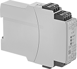
Safety relays have a microprocessor that monitors safety components, such as emergency stops and light curtains, and sends a signal to stop the operation if a failure is detected and restart when the issue is resolved. They also help with diagnostic tasks because of their feedback circuit, which allows basic relays to communicate their status back to the safety relay. They have self-monitoring circuitry, so they’ll keep working even if there’s a component or power failure. Any system that doesn’t have a safety control component will need a safety relay. They meet ISO and IEC standards for performance and safety. Rated IP20, they prevent fingers and other objects from touching live circuits. However, they’re not protected from water.
Power/input/output cables are required for independent and master switches. Data cables are required for connecting switches to your computer. This lets you program and monitor the switches, as well as read their measurement data.
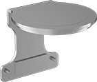
Tilt mounting brackets up and down to make switches scan the correct area. Side-to-side brackets also move left and right. Add protective brackets to shield the tops of switches from falling objects and collisions. Use them with a mounting bracket.


| Safety Zone Sensing Distance Range (Object Size Detected) | Warning Zone Sensing Distance Range | Max. No. of Zone Settings (Socket Connection) | Beam Dia., mm | Input Voltage | Current Output | Signal Output Type | Wd. | Ht. | Dp. | Housing Material | Housing Color | Each | |
Independent Switches | |||||||||||||
|---|---|---|---|---|---|---|---|---|---|---|---|---|---|
8-Pole M12 Socket Connection | |||||||||||||
| 2”-8.2 ft. (1.2”) 2”-9.8 ft. (1.6”, 2”, 2.8”, 5.9”) | 2"-131.2 ft. | 6 (8-Pole M12) | 8 | 24V DC | 250mA | PNP | 4" | 6" | 4.4" | Powder-Coated Aluminum | Yellow | 0000000 | 000000000 |
| 2”-8.2 ft. (1.2”) 2”-9.8 ft. (1.6”) 2”-13.1 ft. (2”) 2”-18 ft. (2.8”, 5.9”) | 2"-131.2 ft. | 6 (8-Pole M12) | 8 | 24V DC | 250mA | PNP | 4" | 6" | 4.4" | Powder-Coated Aluminum | Yellow | 0000000 | 00000000 |
Master Switches | |||||||||||||
8- and 12-Pole M12 Socket Connections | |||||||||||||
| 2”-8.2 ft. (1.2”) 2”-9.8 ft. (1.6”, 2”, 2.8”, 5.9”) | 2"-131.2 ft. | 3 (8-Pole M12) 10 (12-Pole M12) | 8 | 24V DC | 250mA | PNP | 4" | 6" | 4.4" | Powder-Coated Aluminum | Yellow | 0000000 | 00000000 |
| 2”-8.2 ft. (1.2”) 2”-9.8 ft. (1.6”) 2”-13.1 ft. (2”) 2”-18 ft. (2.8”, 5.9”) | 2"-131.2 ft. | 3 (8-Pole M12) 10 (12-Pole M12) | 8 | 24V DC | 250mA | PNP | 4" | 6" | 4.4" | Powder-Coated Aluminum | Yellow | 0000000 | 00000000 |
8- and 17- Pole M12 Socket Connections | |||||||||||||
| 2”-8.2 ft. (1.2”) 2”-9.8 ft. (1.6”, 2”, 2.8”, 5.9”) | 2"-131.2 ft. | 20 (17-Pole M12) 70 (8- and 17-Pole M12) | 8 | 24V DC | 250mA | PNP | 4" | 6" | 4.4" | Powder-Coated Aluminum | Yellow | 0000000 | 00000000 |
| 2”-8.2 ft. (1.2”) 2”-9.8 ft. (1.6”) 2”-13.1 ft. (2”) 2”-18 ft. (2.8”, 5.9”) | 2"-131.2 ft. | 20 (17-Pole M12) 70 (8- and 17-Pole M12) | 8 | 24V DC | 250mA | PNP | 4" | 6" | 4.4" | Powder-Coated Aluminum | Yellow | 0000000 | 00000000 |
Master Switches with Encoder Input | |||||||||||||
8- and 17-Pole M12 Socket Connections | |||||||||||||
| 2”-8.2 ft. (1.2”) 2”-9.8 ft. (1.6”) 2”-13.1 ft. (2”) 2”-18 ft. (2.8”, 5.9”) | 2"-131.2 ft. | 70 (8- and 17-Pole M12) | 8 | 24V DC | 250mA | PNP | 4" | 6" | 4.4" | Powder-Coated Aluminum | Yellow | 0000000 | 00000000 |
Remote Switches | |||||||||||||
| 2”-8.2 ft. (1.2”) 2”-9.8 ft. (1.6”, 2”, 2.8”, 5.9”) | 2"-131.2 ft. | __ | 8 | 24V DC | __ | PNP | 4" | 6" | 4.4" | Powder-Coated Aluminum | Yellow | 0000000 | 00000000 |
| 2”-8.2 ft. (1.2”) 2”-9.8 ft. (1.6”) 2”-13.1 ft. (2”) 2”-18 ft. (2.8”, 5.9”) | 2"-131.2 ft. | __ | 8 | 24V DC | __ | PNP | 4" | 6" | 4.4" | Powder-Coated Aluminum | Yellow | 0000000 | 00000000 |

| Number of Terminals | Input Voltage | Switching Current @ Voltage | Max. Switching Voltage | Wire Connection Type | Ht. | Wd. | Dp. | For Use With | No. of Safety Outputs | Max. System Safety Rating | Features | Each | |
3 Circuits Controlled with 3 Off (Normally Open) | |||||||||||||
|---|---|---|---|---|---|---|---|---|---|---|---|---|---|
| 6 | 24V DC | 6 A @ 240 V AC, 6 A @ 24 V DC | 240V AC | Screw Terminals | 3.7" | 0.9" | 4.8" | Light Curtains | 3 | PLe, SIL3 | Auxiliary PNP Output, Self-Monitoring Circuitry | 0000000 | 0000000 |

Hardwire Connection | |||||
|---|---|---|---|---|---|
| For Component | Plug Type | Wire Connection Type | No. of Wire Leads | Each | |
9.75 ft. Cable Lg. | |||||
| Independent Switch Master Switch Master Switch with Encoder Input | 8-Pole M12 | Wire Leads | 8 | 0000000 | 000000 |
| Master Switch | 12-Pole M12 | Wire Leads | 12 | 0000000 | 00000 |
| Master Switch Master Switch with Encoder Input | 17-Pole M12 | Wire Leads | 17 | 0000000 | 00000 |
32.75 ft. Cable Lg. | |||||
| Independent Switch Master Switch Master Switch with Encoder Input | 8-Pole M12 | Wire Leads | 8 | 0000000 | 00000 |
| Master Switch | 12-Pole M12 | Wire Leads | 12 | 0000000 | 00000 |
| Master Switch Master Switch with Encoder Input | 17-Pole M12 | Wire Leads | 17 | 0000000 | 000000 |
82 ft. Cable Lg. | |||||
| Independent Switch Master Switch Master Switch with Encoder Input | 8-Pole M12 | Wire Leads | 8 | 000000 | 00000 |
| Master Switch | 12-Pole M12 | Wire Leads | 12 | 0000000 | 000000 |
| Master Switch Master Switch with Encoder Input | 17-Pole M12 | Wire Leads | 17 | 0000000 | 000000 |

Mounting | ||||||
|---|---|---|---|---|---|---|
| For Component | Bracket Movement (Range of Motion) | Material | Fasteners Included | Thread Size (No. of Holes) | Each | |
| Independent Switch Master Switch Master Switch with Encoder Input Remote Switch | Up/Down (6°) | Zinc-Plated Steel | No | M5 × 0.8 mm (2) | 0000000 | 000000 |
| Independent Switch Master Switch Master Switch with Encoder Input Remote Switch | Up/Down (6°) Side-to-Side (8.5°) | Zinc-Plated Steel | No | M5 × 0.8 mm (2) | 000000 | 000000 |

| For Component | Material | Mounting Fasteners Included | Each | |
| Independent Switch Master Switch Master Switch with Encoder Input Remote Switch | Zinc-Plated Steel | Yes | 0000000 | 000000 |


