


Choosing an Electrical Switch
More
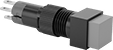
Flush-Mount 16 mm Panel-Mount Push-Button Switches

Because these switches mount flush against a panel, they're easy to clean and hard to damage.
Note: Illuminated switches include a bulb. If wiring the switch and the bulb to the same circuit, the circuit voltage must not exceed bulb voltage.
| No. of Circuits Controlled | Switch Starting Position | Switch Action | No. of Terminals | Industry Designation | Switching Current @ Voltage | Max. Voltage | Dia. | Dp. Behind Panel | For Max. No. of Contact Blocks | Choose an Actuator Color | Environmental Rating | Each | |
Plastic Base with Tab Terminals | |||||||||||||
|---|---|---|---|---|---|---|---|---|---|---|---|---|---|
| 1 | 1 Off (Normally Open) | Springs Back (Momentary) | 4 | SPST-NO | 0.1 A @ 42 V AC/42 V DC | 42V AC 42V DC | 3/4" | 1 3/16" | 1 | IP40 | 000000 | 000000 | |
Plastic Base with Tab Terminals—Illuminated | |||||||||||||
| 1 | 1 Off (Normally Open) | Springs Back (Momentary) | 4 | SPST-NO | 0.1 A @ 42 V AC/42 V DC | 42V AC 42V DC | 3/4" | 1 3/16" | 1 | IP40 | 0000000 | 00000 | |
Plastic Base with Tab Terminals and Push Reset | |||||||||||||
| 1 | 1 Off (Normally Open) | Stays Switched (Maintained) | 4 | SPST-NO | 0.1 A @ 42 V AC/42 V DC | 42V AC 42V DC | 3/4" | 1 3/16" | 1 | IP40 | 000000 | 00000 | |
Plastic Base with Tab Terminals and Push Reset—Illuminated | |||||||||||||
| 1 | 1 Off (Normally Open) | Stays Switched (Maintained) | 4 | SPST-NO | 0.1 A @ 42 V AC/42 V DC | 42V AC 42V DC | 3/4" | 1 3/16" | 1 | IP40 | 0000000 | 00000 | |
8 mm Panel-Mount Push-Button Switches
Install in 8 mm dia. cutouts. A quick push is all it takes to actuate these switches. For an easy way to tell different switches apart, choose a different actuator color for each.
| No. of Circuits Controlled | Switch Starting Position | Switch Action | No. of Terminals | Industry Designation | Switching Current @ Voltage | Max. Voltage | Dia. | Ht. | Wd. | Dp. Behind Panel | Choose an Actuator Color | Specifications Met | Each | |
Plastic Base with Tab Terminals | ||||||||||||||
|---|---|---|---|---|---|---|---|---|---|---|---|---|---|---|
Round (IP40) | ||||||||||||||
| 1 | 1 Off (Normally Open) or 1 On (Normally Closed) | Springs Back (Momentary) | 3 | SPDT | 0.5 A @ 240 V AC, 0.1 A @ 120 V DC | 250V AC 250V DC | 11/32" | __ | __ | 1 1/8" | UL Recognized Component, CSA Certified | 0000000 | 00000 | |
| 1 | 1 Off (Normally Open) or 1 On (Normally Closed) | Stays Switched (Maintained) | 3 | SPDT | 0.5 A @ 240 V AC, 0.1 A @ 120 V DC | 250V AC 250V DC | 11/32" | __ | __ | 1 1/8" | UL Recognized Component, CSA Certified | 0000000 | 00000 | |
Square (IP40) | ||||||||||||||
| 1 | 1 Off (Normally Open) or 1 On (Normally Closed) | Springs Back (Momentary) | 3 | SPDT | 0.5 A @ 240 V AC, 0.1 A @ 120 V DC | 250V AC 250V DC | __ | 11/32" | 11/32" | 1 1/8" | UL Recognized Component, CSA Certified | 0000000 | 0000 | |
| 1 | 1 Off (Normally Open) or 1 On (Normally Closed) | Stays Switched (Maintained) | 3 | SPDT | 0.5 A @ 240 V AC, 0.1 A @ 120 V DC | 250V AC 250V DC | __ | 11/32" | 11/32" | 1 1/8" | UL Recognized Component, CSA Certified | 0000000 | 00000 | |
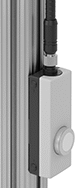
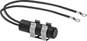
Enclosed Push-Button Switches for T-Slotted Framing
Micro
M12 Plug
Snap these switches onto your T-slotted framing rails—no need to drill or disassemble your existing structure. All come with a mounting bracket that fastens directly onto the rail with the included drop-in fasteners. Their built-in clip hooks onto the bracket, so there’s no need to open the housing to mount them. You can adjust their position by sliding them down the rails. With a push button, they’re quick and easy to actuate.
Switches with IO Link connect to a programmable logic controller (PLC), so you can remotely view outputs and receive error messages from your PC. Often used in production lines, they can let maintenance teams know about problems with equipment before they physically check it.
Micro
M12 Plug
For Rail Height | |||||||||||||
|---|---|---|---|---|---|---|---|---|---|---|---|---|---|
| Single | Double, Quad | Triple | Actuator Color (Industry Designation) | No. of Circuits Controlled per Button | Switch Starting Position | Switch Action | No. of Terminals per Button | Switching Current @ Voltage | Max. Voltage | Bulb Voltage | Mounting Fasteners Included | Each | |
4-Pole Micro M12 Plug and IO Link | |||||||||||||
Illuminated | |||||||||||||
| 1 1/2", 40mm | 3", 80mm | 4 1/2", 120mm | 1 White Button (SPST-NO) | 1 | 1 Off (Normally Open) | Springs Back (Momentary) | 2 | 0.1 A @ 24 V DC | 28V DC | 28V DC | Yes | 0000000 | 0000000 |
Micro
M12 Plug
For Rail Height | |||||||||||||
|---|---|---|---|---|---|---|---|---|---|---|---|---|---|
| Single | Double, Quad | Triple | Actuator Color (Industry Designation) | No. of Circuits Controlled per Button | Switch Starting Position | Switch Action | No. of Terminals per Button | Switching Current @ Voltage | Max. Voltage | Bulb Voltage | Mounting Fasteners Included | Each | |
4-Pole Micro M12 Plug and IO Link | |||||||||||||
Illuminated | |||||||||||||
| 1 1/2", 40mm | 3", 80mm | 4 1/2", 120mm | 2 White Buttons (SPST-NO) | 1 | 1 Off (Normally Open) | Springs Back (Momentary) | 2 | 0.1 A @ 24 V DC | 28V DC | 28V DC | Yes | 0000000 | 0000000 |
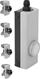
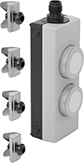
Enabling Pendant Switches
Also known as deadman switches, these switches make sure equipment only runs if you lightly press the hand grip. If you let go or a shock tightens your grip, they cut power. Use them when you need to override a system’s safety controls to program or service equipment. For example, if you need to be in a robot's working area to troubleshoot issues.
Switches with a Buna-N rubber housing work well in dirty and oily environments, such as machine shop floors, because they stand up to fuel oil, hydraulic oil, ethylene glycol, and grease. Because they have a cord on bottom, they can't stand up on their own. Add a mounting bracket to store them upright and out of the way.
Switches with an auxiliary actuator give you control over more components in your system. Red emergency push buttons stop additional equipment with a single push. For example, you could shut down the conveying line a robot is working around. Black push buttons and rockers turn additional equipment, such as inspection lights, on and off.
Switches that meet EN 418 or EN 60947-5-1 comply with European safety standards for emergency stop applications.
Top Push
Button
Emergency
Stop/Top Push Button
| No. of Circuits Controlled | Switch Starting Position | Switch Action | No. of Terminals | Industry Designation | Position Designation | Switching Current @ Voltage | Max. Voltage | Auxiliary Actuator Style (Industry Designation) | Environmental Rating | Specifications Met | Each | |
1 Speed with Screw Terminals | ||||||||||||
|---|---|---|---|---|---|---|---|---|---|---|---|---|
Switches | ||||||||||||
| 2 | 1 Off (Normally Open) or 1 On (Normally Closed) | Springs Back (Momentary) | 3 | SPDT | Off-(On)-Off | 0.5 A @ 250 V AC, 0.1 A @ 125 V DC | 125V DC 250V AC | __ | IP66 | UL Listed C-UL Listed CE Marked | 0000000 | 0000000 |
| 2 | 1 Off (Normally Open) or 1 On (Normally Closed) | Springs Back (Momentary) | 3 | SPDT | Off-(On)-Off | 0.5 A @ 250 V AC, 0.1 A @ 125 V DC | 125V DC 250V AC | 1 Top Black Push Button (SPDT) | IP65 | UL Listed C-UL Listed CE Marked | 0000000 | 000000 |
Switches with Emergency Stop Button | ||||||||||||
| 2 | 1 Off (Normally Open) or 1 On (Normally Closed) | Springs Back (Momentary) | 3 | SPDT | Off-(On)-Off | 0.5 A @ 250 V AC, 0.1 A @ 125 V DC | 125V DC 250V AC | 1 Top Red Push Button (DPST-NC) | IP65 | UL Listed C-UL Listed CE Marked EN 60947-5-1 | 0000000 | 000000 |
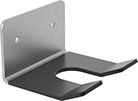
Mounting | |||||
|---|---|---|---|---|---|
| Material | Fasteners Included | No. of Holes | Hole Dia. | Each | |
| Plastic-Coated Stainless Steel | No | 2 | 3/16" | 0000000 | 000000 |
Foot Switches
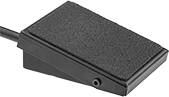
Keep your hands free for other tasks by triggering switches with your foot.
Front-pivot switches reduce fatigue by letting you rest your foot on them. They won't actuate until you lean into them with your bodyweight. Optional guards prevent accidental switch actuation.
Switches | ||||||||||||||
|---|---|---|---|---|---|---|---|---|---|---|---|---|---|---|
Mounting | Optional Guards | |||||||||||||
| No. of Circuits Controlled | Switch Starting Position | Switch Action | Industry Designation | Switching Current @ Voltage | Housing Material | Wire Connection Type | No. of Terminals | Fasteners Included | No. of Holes | Hole Dia. | Each | Each | ||
1 Speed | ||||||||||||||
Front Pivot with 1 Pedal | ||||||||||||||
| 1 | 1 Off (Normally Open) | Springs Back (Momentary) | SPST-NO | 10 A @ 125 V AC/250 V AC, 0.1 A @ 28 V DC | Steel | Wire Leads | __ | No | 2 | 0.12" | 0000000 | 000000 | 0000000 | 000000 |
| 1 | 1 Off (Normally Open) | Stays Switched (Maintained) | SPST-NO | 10 A @ 125 V AC/250 V AC, 0.1 A @ 28 V DC | Steel | Wire Leads | __ | No | 2 | 0.12" | 0000000 | 00000 | 0000000 | 00000 |
| 1 | 1 Off (Normally Open) or 1 On (Normally Closed) | Springs Back (Momentary) | SPDT | 15 A @ 125 V AC/250 V AC, 0.1 A @ 28 V DC | Steel | Quick-Disconnect Terminals | 3 | No | 2 | 0.12" | 0000000 | 00000 | 0000000 | 00000 |
| 1 | 1 Off (Normally Open) or 1 On (Normally Closed) | Stays Switched (Maintained) | SPDT | 15 A @ 125 V AC/250 V AC, 0.1 A @ 28 V DC | Steel | Quick-Disconnect Terminals | 3 | No | 2 | 0.12" | 0000000 | 00000 | 0000000 | 00000 |
Enclosed Wet-Location Snap-Acting Switches
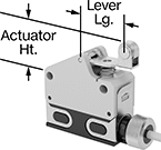
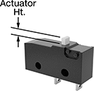
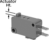
Rated IP67, these switches have an enclosure that shields their interior during temporary submersion. They open and close circuits in a snap—their quick actuation limits arcing and keeps contacts from sticking. These switches are often used to indicate an open appliance or enclosure door. You can also use them inside limit, pressure, and temperature switches. Switches with a plunger actuator require a push to actuate, similar to a button.
Switches with a roller plunger actuator have a roller that moves parallel to the body length when an object pushes the actuator. This reduces friction to limit wear and tear on your switch.
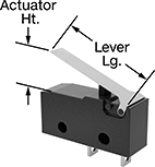
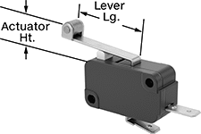
Switches with a roller lever actuator combine the larger actuation area of a standard lever with a smooth gliding roller actuator. They minimize friction to limit wear and tear on your switch.
Switches with a 4-pole micro M12 plug quickly connect and disconnect from your switch. Use cables (sold separately) to wire your switch connection to your setup.
Micro
M12 Plug
Housing | ||||||||||||||
|---|---|---|---|---|---|---|---|---|---|---|---|---|---|---|
| No. of Circuits Controlled | Switch Starting Position | Switch Action | Industry Designation | Switching Current @ Voltage | Max. Voltage | Operating Temp. Range, °F | Actuator Ht. | Lg. | Ht. | Dp. | Lever Lg. | Specifications Met | Each | |
Plunger Actuator Style for 9/16" Panel Cutout Dia. | ||||||||||||||
With 4-Pole Micro M12 Plug | ||||||||||||||
| 1 | 1 Off (Normally Open) or 1 On (Normally Closed) | Springs Back (Momentary) | SPDT | 0.1 A @ 30 V DC | 30V DC | 45° to 155° | 0.79" | 2.24" | 1.3" | 0.71" | __ | EN 60947-5-1 | 0000000 | 0000000 |
Roller Plunger Actuator Style for 9/16" Panel Cutout Dia. | ||||||||||||||
With 4-Pole Micro M12 Plug | ||||||||||||||
| 1 | 1 Off (Normally Open) or 1 On (Normally Closed) | Springs Back (Momentary) | SPDT | 0.1 A @ 30 V DC | 30V DC | 45° to 155° | 1.06" | 2.24" | 1.3" | 0.71" | __ | EN 60947-5-1 | 0000000 | 000000 |
Roller Lever Actuator Style | ||||||||||||||
With 4-Pole Micro M12 Plug | ||||||||||||||
| 1 | 1 Off (Normally Open) or 1 On (Normally Closed) | Springs Back (Momentary) | SPDT | 0.1 A @ 30 V DC | 30V DC | 45° to 155° | 0.73" | 2.24" | 1.3" | 0.71" | 0.79" | EN 60947-5-1 | 0000000 | 000000 |
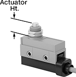
Subminiature Wet-Location Snap-Acting Switches
Built for tight spaces exposed to water, these switches have a housing that's less than 1" long and IP67 rated for protection from temporary submersion. They open and close circuits quickly to minimize arcing and prevent contacts from sticking. They’re often used as door-open indicators on appliances and enclosures or as internal components in limit, pressure, and temperature switches.
Switches with a plunger actuator require a push to actuate.
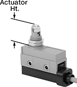
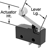
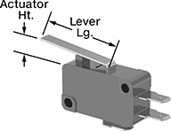
Switches with a lever actuator have an arm that increases the size of the actuation surface.
Switches with a roller lever actuator allow parts to glide across the actuation surface with less friction than standard levers. This prevents wear and tear over time.
Wire Leads | Housing | |||||||||||||||
|---|---|---|---|---|---|---|---|---|---|---|---|---|---|---|---|---|
| No. of Circuits Controlled | Switch Starting Position | Switch Action | Industry Designation | Switching Current @ Voltage | Max. Voltage | Operating Temp. Range, °F | Actuator Ht. | No. of Terminals | No. of | Lg. | Lg. | Ht. | Dp. | Lever Lg. | Each | |
Plunger Actuator Style | ||||||||||||||||
With Wire Leads | ||||||||||||||||
| 1 | 1 Off (Normally Open) or 1 On (Normally Closed) | Springs Back (Momentary) | SPST-NO | 0.1 A @ 125 V AC | 125V AC | -40° to 185° | 0.051" | __ | 2 | 12" | 0.84" | 0.665" | 0.25" | __ | 00000000 | 00000 |
With Quick-Disconnect Terminals | ||||||||||||||||
| 1 | 1 Off (Normally Open) or 1 On (Normally Closed) | Springs Back (Momentary) | SPDT | 0.1 A @ 125 V AC | 125V AC | -40° to 185° | 0.051" | 3 | __ | __ | 0.78" | 0.42" | 0.25" | __ | 00000000 | 0000 |
With Solder Pin Terminals | ||||||||||||||||
| 1 | 1 Off (Normally Open) or 1 On (Normally Closed) | Springs Back (Momentary) | SPDT | 0.1 A @ 125 V AC | 125V AC | -40° to 185° | 0.051" | 3 | __ | __ | 0.78" | 0.42" | 0.25" | __ | 00000000 | 0000 |
Lever Actuator Style | ||||||||||||||||
With Wire Leads | ||||||||||||||||
| 1 | 1 Off (Normally Open) or 1 On (Normally Closed) | Springs Back (Momentary) | SPST-NO | 0.1 A @ 125 V AC | 125V AC | -40° to 185° | 0.189" | __ | 2 | 12" | 0.84" | 0.665" | 0.25" | 0.57" | 00000000 | 00000 |
With Quick-Disconnect Terminals | ||||||||||||||||
| 1 | 1 Off (Normally Open) or 1 On (Normally Closed) | Springs Back (Momentary) | SPDT | 0.1 A @ 125 V AC | 125V AC | -40° to 185° | 0.189" | 3 | __ | __ | 0.78" | 0.42" | 0.23" | 0.57" | 00000000 | 0000 |
With Solder Pin Terminals | ||||||||||||||||
| 1 | 1 Off (Normally Open) or 1 On (Normally Closed) | Springs Back (Momentary) | SPDT | 0.1 A @ 125 V AC | 125V AC | -40° to 185° | 0.189" | 3 | __ | __ | 0.78" | 0.42" | 0.23" | 0.57" | 00000000 | 0000 |
Roller Lever Actuator Style | ||||||||||||||||
With Wire Leads | ||||||||||||||||
| 1 | 1 Off (Normally Open) or 1 On (Normally Closed) | Springs Back (Momentary) | SPST-NO | 0.1 A @ 125 V AC | 125V AC | -40° to 185° | 0.362" | __ | 2 | 12" | 0.84" | 0.665" | 0.25" | 0.57" | 00000000 | 0000 |
With Quick-Disconnect Terminals | ||||||||||||||||
| 1 | 1 Off (Normally Open) or 1 On (Normally Closed) | Springs Back (Momentary) | SPDT | 0.1 A @ 125 V AC | 125V AC | -40° to 185° | 0.362" | 3 | __ | __ | 0.78" | 0.42" | 0.25" | 0.57" | 00000000 | 0000 |
With Solder Pin Terminals | ||||||||||||||||
| 1 | 1 Off (Normally Open) or 1 On (Normally Closed) | Springs Back (Momentary) | SPDT | 0.1 A @ 125 V AC | 125V AC | -40° to 185° | 0.362" | 3 | __ | __ | 0.78" | 0.42" | 0.25" | 0.57" | 00000000 | 0000 |
Subminiature Snap-Acting Switches
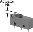
At least 25% smaller than our Miniature Snap-Acting Switches, these switches are often used to trigger actions from inside a vehicle’s door or an engine compartment. They open and close circuits faster than other switches, preventing contacts from sticking by reducing the time that they're near one another. They also minimize the chance of arcing, so electricity won’t jump across contacts.
Plunger actuator switches send a signal when the actuator is pushed directly downward. They have the smallest actuator of the actuators here, reducing the risk of accidental switching.
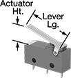
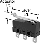
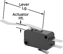
Lever actuator switches have a larger surface area than plunger actuator switches and can be pushed down by front-to-back movement, so they require less precision to activate.
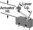
Roller lever actuator switches allow parts to glide across the actuation surface with less friction than standard levers. This prevents wear and tear over time.
Simulated roller lever actuator switches have a curved arm that can be pressed down for actuation by forward, backward, and repeated back-and-forth movement.
Housing | |||||||||||||||
|---|---|---|---|---|---|---|---|---|---|---|---|---|---|---|---|
| No. of Circuits Controlled | Switch Starting Position | Switch Action | Industry Designation | Switching Current @ Voltage | Max. Voltage | Operating Temp. Range, °F | Actuator Ht. | No. of Terminals | Lg. | Ht. | Dp. | Lever Lg. | Environmental Rating | Each | |
Plunger Actuator Style | |||||||||||||||
With Solder Pin Terminals | |||||||||||||||
| 1 | 1 Off (Normally Open) or 1 On (Normally Closed) | Springs Back (Momentary) | SPDT | 0.1 A @ 125 V AC | 125V AC | -10° to 185° | 0.03" | 3 | 0.78" | 0.35" | 0.25" | __ | IP40 | 00000000 | 00000 |
With Tab Terminals | |||||||||||||||
| 1 | 1 Off (Normally Open) or 1 On (Normally Closed) | Springs Back (Momentary) | SPDT | 0.1 A @ 125 V AC | 125V AC | -10° to 185° | 0.03" | 3 | 0.78" | 0.35" | 0.25" | __ | IP40 | 00000000 | 0000 |
Lever Actuator Style | |||||||||||||||
With Solder Pin Terminals | |||||||||||||||
| 1 | 1 Off (Normally Open) or 1 On (Normally Closed) | Springs Back (Momentary) | SPDT | 0.1 A @ 125 V AC | 125V AC | -10° to 185° | 0.26" | 3 | 0.78" | 0.35" | 0.25" | 0.57" | IP40 | 00000000 | 0000 |
With Tab Terminals | |||||||||||||||
| 1 | 1 Off (Normally Open) or 1 On (Normally Closed) | Springs Back (Momentary) | SPDT | 0.1 A @ 125 V AC | 125V AC | -10° to 185° | 0.26" | 3 | 0.78" | 0.35" | 0.25" | 0.57" | IP40 | 00000000 | 0000 |
Roller Lever Actuator Style | |||||||||||||||
With Solder Pin Terminals | |||||||||||||||
| 1 | 1 Off (Normally Open) or 1 On (Normally Closed) | Springs Back (Momentary) | SPDT | 0.1 A @ 125 V AC | 125V AC | -10° to 185° | 0.48" | 3 | 0.78" | 0.35" | 0.25" | 0.57" | IP40 | 00000000 | 0000 |
With Tab Terminals | |||||||||||||||
| 1 | 1 Off (Normally Open) or 1 On (Normally Closed) | Springs Back (Momentary) | SPDT | 0.1 A @ 125 V AC | 125V AC | -10° to 185° | 0.48" | 3 | 0.78" | 0.35" | 0.25" | 0.57" | IP40 | 00000000 | 0000 |
Simulated Roller Lever Actuator Style | |||||||||||||||
With Solder Pin Terminals | |||||||||||||||
| 1 | 1 Off (Normally Open) or 1 On (Normally Closed) | Springs Back (Momentary) | SPDT | 0.1 A @ 125 V AC | 125V AC | -10° to 185° | 0.34" | 3 | 0.78" | 0.35" | 0.25" | 0.62" | IP40 | 00000000 | 0000 |
With Tab Terminals | |||||||||||||||
| 1 | 1 Off (Normally Open) or 1 On (Normally Closed) | Springs Back (Momentary) | SPDT | 0.1 A @ 125 V AC | 125V AC | -10° to 185° | 0.34" | 3 | 0.78" | 0.35" | 0.25" | 0.62" | IP40 | 00000000 | 0000 |
Light-Touch Miniature Snap-Acting Switches
Smaller and more sensitive than standard snap-acting switches, these switches fit in tight spaces and actuate from light pressure. Snap-acting switches quickly open or close circuits to reduce arcing and keep contacts from sticking.
Switches with a plunger actuator require a push to activate, similar to a button.
Switches with a lever actuator activate when material moves across the arm, which provides a large actuation area.
Switches with a roller lever actuator use a lever with a roller at the end to activate. This allows parts to glide across the actuation surface with minimal friction, limiting wear and tear.
Switches with an angled lever actuator have an arm with a tapered end. This creates an extra angle for actuation.
Housing | ||||||||||||||
|---|---|---|---|---|---|---|---|---|---|---|---|---|---|---|
| Number of Circuits Controlled | Switch Starting Position | Switch Action | Industry Designation | Switching Current @ Voltage | Max. Voltage | Operating Temp.Range, °F | Actuator Ht. | No. of Terminals | Lg. | Ht. | Dp. | Lever Lg. | Each | |
Plunger Actuator Style | ||||||||||||||
With Quick-Disconnect Terminals | ||||||||||||||
| 1 | 1 Off (Normally Open) | Springs Back (Momentary) | SPST-NO | 0.1 A @ 125 V AC, 0.1 A @ 30 V DC | 125V AC 30V DC | -13° to 220° | 0.11" | 2 | 1.1" | 0.63" | 0.4" | __ | 0000000 | 00000 |
| 1 | 1 Off (Normally Open) or 1 On (Normally Closed) | Springs Back (Momentary) | SPDT | 0.1 A @ 125 V AC | 125V AC | -40° to 180° | 0.11" | 3 | 1.1" | 0.63" | 0.4" | __ | 0000000 | 0000 |
Lever Actuator Style | ||||||||||||||
With Quick-Disconnect Terminals | ||||||||||||||
| 1 | 1 Off (Normally Open) or 1 On (Normally Closed) | Springs Back (Momentary) | SPDT | 0.1 A @ 125 V AC | 125V AC | -40° to 180° | 0.22" | 3 | 1.1" | 0.63" | 0.4" | 1.1" | 0000000 | 0000 |
Roller Lever Actuator Style | ||||||||||||||
With Quick-Disconnect Terminals | ||||||||||||||
| 1 | 1 Off (Normally Open) or 1 On (Normally Closed) | Springs Back (Momentary) | SPDT | 0.1 A @ 125 V AC | 125V AC | -40° to 180° | 0.34" | 3 | 1.1" | 0.63" | 0.4" | 0.5" | 0000000 | 0000 |
Angled Lever Actuator Style | ||||||||||||||
With Quick-Disconnect Terminals | ||||||||||||||
| 1 | 1 Off (Normally Open) or 1 On (Normally Closed) | Springs Back (Momentary) | SPDT | 0.1 A @ 125 V AC | 125V AC | -40° to 180° | 0.15" | 3 | 1.1" | 0.63" | 0.4" | 0.5" | 0000000 | 00000 |
| 1 | 1 Off (Normally Open) or 1 On (Normally Closed) | Springs Back (Momentary) | SPDT | 0.1 A @ 125 V AC | 125V AC | -40° to 180° | 0.35" | 3 | 1.1" | 0.63" | 0.4" | 0.87" | 00000000 | 0000 |
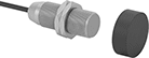
Magnetically Actuated Switches
These switches actuate when a magnet comes within sensing distance, and reset when the magnet moves away. They’re often used to detect when a door or window opens. Mount the switch in a stationary position, such as a door frame, and mount the magnet to a movable object, such as the door. They do not include a safety relay and cannot be used with safety-guard doors found on machinery.
Switches with a plug connect to cables with a socket (sold separately), allowing you to quickly connect and disconnect the switch.
Switches with an LED status indicator let you visually confirm that it’s connected and whether it’s actuated.
IP65 rated switches protect against rinsing and dust. IP68 rated switches protect against washdowns and continuous submersion. Use IP69K rated switches in demanding environments, such as roadways.
Micro
M12 Plug
Switches | Replacement Magnets | |||||||||||||
|---|---|---|---|---|---|---|---|---|---|---|---|---|---|---|
| No. of Circuits Controlled | Switch Starting Position | Industry Designation | Switching Current @ Voltage | Max. Voltage | Max. Sensing Distance | Dia. | Lg. | Mount. Thread Size | Environmental Rating | Each | Each | |||
Stainless Steel Housing | ||||||||||||||
With 4-Pole Micro M12 Plug and LED Status Indicator | ||||||||||||||
| K | 1 | 1 Off (Normally Open) | SPST-NO | 0.1 A @ 3 V DC | 30V DC | 2.36" | 0.47" | 2.36" | M12 | IP65, IP68, IP69K | 000000000 | 0000000 | 000000000 | 000000 |
| K | 1 | 1 Off (Normally Open) | SPST-NO | 0.1 A @ 3 V DC | 30V DC | 2.75" | 0.71" | 2.36" | M18 | IP65, IP68, IP69K | 000000000 | 000000 | 000000000 | 00000 |
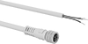
| No. of Poles | Cable Lead Lg., ft. | Environmental Rating | Each | |
Micro M12 Socket × Wire Leads | ||||
|---|---|---|---|---|
| 4 | 12 | IP67 | 0000000 | 000000 |
Tilt Switches
Often used as position indicators, pump level controls, and machine limit switches, these switches actuate when tilted to a certain angle. They mount horizontally and activate when tilted downward, and deactivate when tilted up. Differential angle is the total angle from the point of activation to the point of deactivation. All combine electromechanical and solid state technologies for reliability and long life.
| No. of Circuits Controlled | Switch Starting Position | Industry Designation | Switching Current @ Voltage | Max. Voltage | Differential Angle | No. of Wire Leads | Dia. | Lg. | Housing Material | Environmental Rating | Each | ||
With Ring Terminals | |||||||||||||
|---|---|---|---|---|---|---|---|---|---|---|---|---|---|
| A | 1 | 1 Off (Normally Open) | SPST-NO | 0.1 A @ 120 V AC, 0.25 A @ 24 V DC | 60V DC/120V AC | 15° | 2 | 0.53" | 1.88" | Plastic | NEMA 4, IP67 | 000000 | 000000 |
DIN-Rail Mount Solid State Interface Relays
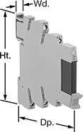
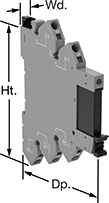
With no moving parts, these solid state relays last longer, switch faster, and are quieter than mechanical relays. They interface between your controller and components to isolate input and output circuits, which protects components from voltage spikes, amplifies the relay’s signal, and reduces interference for reliable transmission. The relay’s LED indicator shines when it’s powered on, so you know at a glance which relays are wired correctly and what the switching position is. These relays are often used for switching small motors and sensors. Rated IP20, they prevent fingers and other objects from touching live circuits.
Mount them on 35 mm DIN rail (also known as DIN 3 rail) with the included socket. Relays disconnect from the socket for easy replacement.
Relays with spring-clamp terminals connect and disconnect to wires without needing to turn screws. With no screws to shake loose with vibration, these terminals hold tight over time.
Relays with Relay Socket and Retaining Clip | Replacement Relays | |||||||||||
|---|---|---|---|---|---|---|---|---|---|---|---|---|
| Number of Terminals | Input Voltage | Output Voltage | Control Current, mA | Switching Current @ Voltage | Max. Switching Voltage | Ht. | Wd. | Dp. | Each | Each | ||
1 Circuit Controlled with 1 Off (Normally Open)—SPST-NO | ||||||||||||
With Screw Terminals | ||||||||||||
| 5 | 24V AC, 48V AC, 120V AC, 240V AC, 24V DC, 48V DC, 60V DC, 120V DC, 240V DC | 0-48V DC | 22 | 100 mA @ 48 V DC | 48V DC | 3.5" | 0.2" | 3.4" | 0000000 | 000000 | 0000000 | 000000 |
| 5 | 24V DC | 3-48V DC | 8.5 | 100 mA @ 48 V DC | 48V DC | 3.1" | 0.2" | 3.7" | 0000000 | 00000 | 000000 | 00 |
With Spring-Clamp Terminals | ||||||||||||
| 4 | 24V DC | __ | 10.5 | 100 mA @ 48 V DC | 53V DC | 3.7" | 0.2" | 3" | 00000000 | 00000 | 00000000 | 00000 |