


Filter by
Switching Voltage
Switching Current
Actuator Style
Illumination
Mount Type

Switch Action
Wire Connection
Switch Starting Position
Export Control Classification Number (ECCN)
DFARS Specialty Metals

About Electrical Switches
Choose a switch with the right trigger type, number of inputs, and control functions to power your equipment.
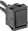
Rocker Switches
 |  |  |
Style A | Style B | Style C |
 |  | |
Style D | Style E |
The wide surface of these switches makes them easy to press on and off, even if your hands are full and you need to use an elbow. They’re often used as power switches on electronic devices and control panels.
Note: Illuminated switches include a bulb. If wiring the switch and the bulb to the same circuit, the circuit voltage must not exceed the bulb voltage.
Illuminated—Illuminated switches are easy to see in dim and dark areas. They come in red and green, so you can color code your set up.
For 13/16" Diameter Panel Cutouts—Switches for a 13/16” dia. panel cutout are round, so you can use a drill bit or knockout to install them instead of cutting a rectangular hole.
On-On—Switches with an on-on position designation alternate power between sets of terminals.
Style | No. of Circuits Controlled | Switch Starting Position | Switch Action | No. of Terminals | Switch Designation | Position Designation | Switching Current @ Voltage | Max. Voltage, V AC | Bulb Voltage, V AC | Quick-Disconnect Tab Wd. | Bulb Type | Choose a Color | Each | |||
|---|---|---|---|---|---|---|---|---|---|---|---|---|---|---|---|---|
2 Positions with Quick-Disconnect Terminals | ||||||||||||||||
For 13/16" Diameter Panel Cutouts | ||||||||||||||||
| A | 1 | 1 Off | Maintained | 3 | SPST-NO | On-On | 16 amp @ 125V AC, 10 amp @ 250V AC | 250 | — | 0.189" | — | Black | 7395K129 | 00000 | ||
| A | 1 | 1 On | Maintained | 2 | SPST-NC | On-Off | 16 amp @ 125V AC, 10 amp @ 250V AC | 250 | — | 0.189" | — | Black | 7395K128 | 0000 | ||
| B | 2 | 2 Off | Maintained | 4 | DPST-NO | On-Off | 16 amp @ 125V AC, 10 amp @ 250V AC | 250 | — | 0.189" | — | Black | 7395K119 | 0000 | ||
| B | 2 | 2 Off or 2 On | Maintained | 4 | DPDT | On-On | 16 amp @ 125V AC, 10 amp @ 250V AC | 250 | — | 0.189" | — | Black | 7395K134 | 0000 | ||
For 1 1/8" High × 9/16" Wide Panel Cutouts | ||||||||||||||||
| C | 1 | 1 Off | Maintained | 2 | SPST-NO | On-Off | 16 amp @ 125V AC | 250 | — | 0.25" | — | Black | 7395K11 | 0000 | ||
| C | 1 | 1 Off or 1 On | Maintained | 3 | SPDT | On-On | 16 amp @ 125V AC | 250 | — | 0.25" | — | Black | 7395K12 | 0000 | ||
For 1 3/16" High × 7/16" Wide Panel Cutouts | ||||||||||||||||
| C | 1 | 1 Off | Maintained | 2 | SPST-NO | On-Off | 20 amp @ 125V AC, 16 amp @ 250V AC | 250 | — | 0.25" | — | Black | 7395K111 | 0000 | ||
| C | 1 | 1 Off or 1 On | Maintained | 3 | SPDT | On-On | 20 amp @ 125V AC, 16 amp @ 250V AC | 250 | — | 0.25" | — | Black | 7395K112 | 0000 | ||
For 1 3/16" High × 7/8" Wide Panel Cutouts | ||||||||||||||||
| C | 2 | 2 Off | Maintained | 4 | DPST-NO | On-Off | 16 amp @ 125V AC | 250 | — | 0.25" | — | Black | 7395K13 | 0000 | ||
| C | 2 | 2 Off | Maintained | 4 | DPST-NO | On-Off | 20 amp @ 125V AC, 16 amp @ 250V AC | 250 | — | 0.25" | — | Black | 7395K114 | 0000 | ||
| C | 2 | 2 Off or 2 On | Maintained | 6 | DPDT | On-On | 16 amp @ 125V AC | 250 | — | 0.25" | — | Black | 7395K14 | 0000 | ||
| C | 2 | 2 Off or 2 On | Maintained | 6 | DPDT | On-On | 20 amp @ 125V AC, 16 amp @ 250V AC | 250 | — | 0.25" | — | Black | 7395K115 | 0000 | ||
2 Positions with Quick-Disconnect Terminals—Illuminated | ||||||||||||||||
For 13/16" Diameter Panel Cutouts | ||||||||||||||||
| D | 1 | 1 On | Maintained | 3 | SPST-NC | On-Off | 16 amp @ 125V AC, 10 amp @ 250V AC | 250 | 125 | 0.189" | Neon | Green, Red | 7395K103 | 0000 | ||
| E | 2 | 2 Off | Maintained | 2 | DPST-NO | On-Off | 16 amp @ 125V AC, 10 amp @ 250V AC | 250 | 110 | 0.189" | Neon | Green, Red | 7395K101 | 0000 | ||
3 Positions with Quick-Disconnect Terminals | ||||||||||||||||
For 13/16" Diameter Panel Cutouts | ||||||||||||||||
| A | 1 | 1 Off | Maintained | 3 | SPST-NO | On-Off-On | 16 amp @ 125V AC, 10 amp @ 250V AC | 250 | — | 0.189" | — | Black | 7395K135 | 0000 | ||
| B | 2 | 2 Off or 2 On | Maintained | 6 | DPDT | On-Off-On | 16 amp @ 125V AC, 10 amp @ 250V AC | 250 | — | 0.189" | — | Black | 7395K121 | 0000 | ||
High-Starting-Current Rocker Switches
 |  |  |  |  |  |
Blank | Horizontal Line/Circle | Vertical Line/Circle | Blank with Wire Leads | Horizontal Line/Circle with Wire Leads | Vertical Line/Circle with Wire Leads |
Wire Leads | |||||||||||||||
|---|---|---|---|---|---|---|---|---|---|---|---|---|---|---|---|
No. of Circuits Controlled | Switch Starting Position | Switch Action | No. of Terminals | Switch Designation | Position Designation | Message (Location) | Switching Current @ Voltage | Max. Voltage | No. of | Lg. | Choose a Color | Each | |||
2 Positions with Tab Terminals | |||||||||||||||
For 1 3/16" High × 13/16" Wide Panel Cutouts | |||||||||||||||
| 1 | 1 Off | Maintained | 2 | SPST-NO | On-Off | Blank (Top), Blank (Bottom) | 16 amp @ 125V AC, 5 amp @ 30V DC | 250V AC, 72V DC | — | — | Black, Red | 7194K28 | 000000 | ||
| 1 | 1 Off | Maintained | 2 | SPST-NO | On-Off | Horizontal Line (Top), Circle (Bottom) | 16 amp @ 125V AC, 5 amp @ 30V DC | 250V AC, 72V DC | — | — | Black, Red | 7194K33 | 00000 | ||
| 1 | 1 Off | Maintained | 2 | SPST-NO | On-Off | Vertical Line (Top), Circle (Bottom) | 16 amp @ 125V AC, 5 amp @ 30V DC | 250V AC, 72V DC | — | — | Black, Red | 7194K34 | 00000 | ||
| 1 | 1 Off or 1 On | Maintained | 3 | SPDT | On-On | Blank (Top), Blank (Bottom) | 16 amp @ 125V AC, 5 amp @ 30V DC | 250V AC, 72V DC | — | — | Black, Red | 7194K29 | 00000 | ||
| 2 | 2 Off | Maintained | 4 | DPST-NO | On-Off | Blank (Top), Blank (Bottom) | 16 amp @ 125V AC, 5 amp @ 30V DC | 250V AC, 72V DC | — | — | Black, Red | 7194K31 | 00000 | ||
| 2 | 2 Off | Maintained | 4 | DPST-NO | On-Off | Horizontal Line (Top), Circle (Bottom) | 16 amp @ 125V AC, 5 amp @ 30V DC | 250V AC, 72V DC | — | — | Black, Red | 7194K35 | 00000 | ||
| 2 | 2 Off | Maintained | 4 | DPST-NO | On-Off | Vertical Line (Top), Circle (Bottom) | 16 amp @ 125V AC, 5 amp @ 30V DC | 250V AC, 72V DC | — | — | Black, Red | 7194K36 | 00000 | ||
| 2 | 2 Off or 2 On | Maintained | 6 | DPDT | On-On | Blank (Top), Blank (Bottom) | 16 amp @ 125V AC, 5 amp @ 30V DC | 250V AC, 72V DC | — | — | Black, Red | 7194K32 | 00000 | ||
2 Positions with Wire Leads | |||||||||||||||
For 1 3/16" High × 13/16" Wide Panel Cutouts | |||||||||||||||
| 1 | 1 Off | Maintained | 2 | SPST-NO | On-Off | Blank (Top), Blank (Bottom) | 16 amp @ 120V AC, 5 amp @ 24V DC | 250V AC, 72V DC | 2 | 12" | Black, Red | 7194K58 | 00000 | ||
| 1 | 1 Off | Maintained | 2 | SPST-NO | On-Off | Horizontal Line (Top), Circle (Bottom) | 16 amp @ 120V AC, 5 amp @ 24V DC | 250V AC, 72V DC | 2 | 12" | Black | 7194K53 | 00000 | ||
| 1 | 1 Off | Maintained | 2 | SPST-NO | On-Off | Vertical Line (Top), Circle (Bottom) | 16 amp @ 120V AC, 5 amp @ 24V DC | 250V AC, 72V DC | 2 | 12" | Black, Red | 7194K59 | 00000 | ||
| 2 | 2 Off | Maintained | 4 | DPST-NO | On-Off | Blank (Top), Blank (Bottom) | 16 amp @ 120V AC, 5 amp @ 24V DC | 250V AC, 72V DC | 4 | 12" | Black | 7194K54 | 00000 | ||
| 2 | 2 Off | Maintained | 4 | DPST-NO | On-Off | Horizontal Line (Top), Circle (Bottom) | 16 amp @ 120V AC, 5 amp @ 24V DC | 250V AC, 72V DC | 4 | 12" | Black, Red | 7194K62 | 00000 | ||
| 2 | 2 Off | Maintained | 4 | DPST-NO | On-Off | Vertical Line (Top), Circle (Bottom) | 16 amp @ 120V AC, 5 amp @ 24V DC | 250V AC, 72V DC | 4 | 12" | Black | 7194K55 | 00000 | ||
| 2 | 2 Off or 2 On | Maintained | 6 | DPDT | On-On | Blank (Top), Blank (Bottom) | 16 amp @ 120V AC, 5 amp @ 24V DC | 250V AC, 72V DC | 6 | 12" | Black | 7194K57 | 00000 | ||
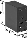
Panel-Mount Compact Disconnect Switches
Maintained Switch%20--%3e%3csvg%20version='1.1'%20id='Layer_1'%20xmlns='http://www.w3.org/2000/svg'%20xmlns:xlink='http://www.w3.org/1999/xlink'%20x='0px'%20y='0px'%20viewBox='0%200%20400%20400'%20style='enable-background:new%200%200%20400%20400;'%20xml:space='preserve'%3e%3cstyle%20type='text/css'%3e%20.st0{fill:%231A70A0;}%20.st1{opacity:0.5;}%20%3c/style%3e%3cg%3e%3cg%3e%3cpath%20class='st0'%20d='M200,56.9c38.35,0,74.4,14.93,101.51,42.05c27.11,27.11,42.05,63.17,42.05,101.51s-14.93,74.4-42.05,101.51%20S238.35,344.02,200,344.02s-74.4-14.93-101.51-42.05c-27.11-27.11-42.05-63.17-42.05-101.51s14.93-74.4,42.05-101.51%20S161.65,56.9,200,56.9%20M200,12.9C96.41,12.9,12.44,96.88,12.44,200.46c0,103.59,83.97,187.56,187.56,187.56%20c103.59,0,187.56-83.97,187.56-187.56C387.56,96.88,303.59,12.9,200,12.9L200,12.9z'/%3e%3c/g%3e%3cg%3e%3cg%20class='st1'%3e%3cpath%20class='st0'%20d='M235.49,152.24h16.15l-27.46,111.87c-1.94,7.8-2.91,12.5-2.91,14.1c0,1.82,0.58,3.29,1.73,4.41%20c1.16,1.12,2.69,1.68,4.61,1.68c5.23,0,11.78-3.85,19.63-11.55l17.22,21.34c-16.95,17.33-34.87,26-53.78,26%20c-8.37,0-15.45-1.47-21.23-4.41c-5.79-2.94-10.44-7.25-13.95-12.92c-3.51-5.67-5.27-11.18-5.27-16.53c0-1.93,0.35-5.24,1.05-9.94%20c1-6.94,2.05-12.54,3.15-16.82l15.22-62.15h-32.69l7.65-30.97C190.89,163.58,214.53,158.88,235.49,152.24z%20M230.44,80.84%20c8.24,0,14.66,2.62,19.26,7.86c4.6,5.24,6.9,11.55,6.9,18.94c0,5.46-1.42,10.7-4.25,15.73c-2.83,5.03-6.88,9.07-12.12,12.12%20c-5.24,3.05-10.33,4.57-15.24,4.57c-4.6,0-9.17-1.23-13.72-3.69c-4.55-2.46-8.02-5.78-10.43-9.95%20c-2.41-4.17-3.61-8.67-3.61-13.48c0-5.35,1.52-10.64,4.57-15.89c3.05-5.24,7.03-9.25,11.96-12.04%20C218.68,82.23,224.24,80.84,230.44,80.84z'/%3e%3c/g%3e%3cg%3e%3cpath%20class='st0'%20d='M214.08,152.24h16.15l-27.46,111.87c-1.94,7.8-2.91,12.5-2.91,14.1c0,1.82,0.58,3.29,1.73,4.41%20c1.16,1.12,2.69,1.68,4.61,1.68c5.23,0,11.78-3.85,19.63-11.55l17.22,21.34c-16.95,17.33-34.87,26-53.78,26%20c-8.37,0-15.45-1.47-21.23-4.41c-5.79-2.94-10.44-7.25-13.95-12.92c-3.51-5.67-5.27-11.18-5.27-16.53c0-1.93,0.35-5.24,1.05-9.94%20c1-6.94,2.05-12.54,3.15-16.82l15.22-62.15h-32.69l7.65-30.97C169.48,163.58,193.11,158.88,214.08,152.24z%20M209.03,80.84%20c8.24,0,14.66,2.62,19.26,7.86c4.6,5.24,6.9,11.55,6.9,18.94c0,5.46-1.42,10.7-4.25,15.73c-2.83,5.03-6.88,9.07-12.12,12.12%20c-5.24,3.05-10.33,4.57-15.24,4.57c-4.6,0-9.17-1.23-13.72-3.69c-4.55-2.46-8.02-5.78-10.43-9.95%20c-2.41-4.17-3.61-8.67-3.61-13.48c0-5.35,1.52-10.64,4.57-15.89c3.05-5.24,7.03-9.25,11.96-12.04%20C197.26,82.23,202.83,80.84,209.03,80.84z'/%3e%3c/g%3e%3c/g%3e%3c/g%3e%3c/svg%3e)
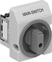 |
Lockout—All switches have a lockout so you can secure them in the off position with a padlock (not included).
IP65 Enclosure Rating—They’re rated IP65 for protection from washdowns.
Switching Current @ Voltage | Switch Designation | Electrical Phase (hp) | Ht. | Wd. | Dp. Behind Panel | For Max. Padlock Shackle Dia. | Enclosure Rating | Certification | Specs. Met | Each | |||
|---|---|---|---|---|---|---|---|---|---|---|---|---|---|
Gray Plastic Housing with Black Actuator | |||||||||||||
3 Circuits Controlled with Lockout—For 3/8" Dia. Panel Cutouts | |||||||||||||
| 12 amp @ 600V AC, 16 amp @ 24V DC | 3PST | Single (1/2 hp @ 120V AC) Three (1 hp @ 120V AC) Three (3 hp @ 240V AC) | 3 1/4" | 2 1/2" | 1 13/16" | 5/16" | IP65 | UL Recognized Component | UL 508 | 65915K101 | 000000 | ||
| 16 amp @ 600V AC, 20 amp @ 24V DC | 3PST | Single (1 hp @ 120V AC) Three (2 hp @ 120V AC) Three (5 hp @ 240V AC) | 3 1/4" | 2 1/2" | 1 13/16" | 5/16" | IP65 | UL Recognized Component | UL 508 | 65915K102 | 00000 | ||
4 Circuits Controlled with Lockout—For 3/8" Dia. Panel Cutouts | |||||||||||||
| 12 amp @ 600V AC, 16 amp @ 24V DC | 4PST | Single (1/2 hp @ 120V AC) Three (1 hp @ 120V AC) Three (3 hp @ 240V AC) | 3 1/4" | 2 1/2" | 1 13/16" | 5/16" | IP65 | UL Recognized Component | UL 508 | 65915K107 | 00000 | ||
| 16 amp @ 600V AC, 20 amp @ 24V DC | 4PST | Single (1 hp @ 120V AC) Three (2 hp @ 120V AC) Three (5 hp @ 240V AC) | 3 1/4" | 2 1/2" | 1 13/16" | 5/16" | IP65 | UL Recognized Component | UL 508 | 65915K108 | 00000 | ||
Yellow Plastic Housing with Red Actuator | |||||||||||||
3 Circuits Controlled with Lockout—For 3/8" Dia. Panel Cutouts | |||||||||||||
| 12 amp @ 600V AC, 16 amp @ 24V DC | 3PST | Single (1/2 hp @ 120V AC) Three (1 hp @ 120V AC) Three (3 hp @ 240V AC) | 3 1/4" | 2 1/2" | 1 13/16" | 5/16" | IP65 | UL Recognized Component | UL 508 | 65915K11 | 00000 | ||
| 16 amp @ 600V AC, 20 amp @ 24V DC | 3PST | Single (1 hp @ 120V AC) Three (2 hp @ 120V AC) Three (5 hp @ 240V AC) | 3 1/4" | 2 1/2" | 1 13/16" | 5/16" | IP65 | UL Recognized Component | UL 508 | 65915K12 | 00000 | ||
4 Circuits Controlled with Lockout—For 3/8" Dia. Panel Cutouts | |||||||||||||
| 12 amp @ 600V AC, 16 amp @ 24V DC | 4PST | Single (1/2 hp @ 120V AC) Three (1 hp @ 120V AC) Three (3 hp @ 240V AC) | 3 1/4" | 2 1/2" | 1 13/16" | 5/16" | IP65 | UL Recognized Component | UL 508 | 65915K41 | 00000 | ||
| 16 amp @ 600V AC, 20 amp @ 24V DC | 4PST | Single (1 hp @ 120V AC) Three (2 hp @ 120V AC) Three (5 hp @ 240V AC) | 3 1/4" | 2 1/2" | 1 13/16" | 5/16" | IP65 | UL Recognized Component | UL 508 | 65915K42 | 00000 | ||
High-Current Toggle Switches
 |
Able to withstand high currents, these switches are often used with motors and pumps.
No. of Circuits Controlled | Switch Starting Position | Switch Action | No. of Terminals | Switch Designation | Position Designation | Switching Current @ Voltage | Max. Voltage | Dp. Behind Panel | Mounting Hardware Included | Each | |||
|---|---|---|---|---|---|---|---|---|---|---|---|---|---|
2 Position with Screw Terminals | |||||||||||||
For 1/2" Diameter Panel Cutouts | |||||||||||||
| 1 | 1 Off | Maintained | 2 | SPST-NO | On-Off | 16 amp @ 125V AC, 8 amp @ 30V DC | 250V DC 250V AC | 0.77" | Yes | 8001K51 | 000000 | ||
| 2 | 2 Off | Maintained | 4 | DPST-NO | On-Off | 16 amp @ 125V AC, 8 amp @ 30V DC | 250V DC 250V AC | 0.77" | Yes | 8001K53 | 00000 | ||
Submersible High-Starting-Current Rocker Switches
 |  |
Blank | Horizontal Line/Circle |
Rated IP67 for protection from dust and temporary submersion. Also known as high-inrush current switches, these switches can handle starting currents up to 10 times greater than their current rating, such as when a motor starts. They're often used with amplifiers, power supplies, and other high-starting-current devices. Easy to press, these switches have a wide, flat actuation area. Color-code your switches so that operators can identify their function at a glance.
No. of Circuits Controlled | Switch Starting Position | Switch Action | No. of Terminals | Switch Designation | Position Designation | Message (Location) | Switching Current @ Voltage | Max. Voltage, V AC | Quick-Disconnect Tab Wd. | Choose a Color | Each | |||
|---|---|---|---|---|---|---|---|---|---|---|---|---|---|---|
2 Positions with Quick-Disconnect Terminals | ||||||||||||||
For 1 7/32" High × 13/16" Wide Panel Cutouts | ||||||||||||||
| 2 | 2 Off | Maintained | 4 | DPST-NO | On-Off | Horizontal Line (Top), Circle (Bottom) | 16 amp @ 125V AC | 250 | 0.187" | Black, Red | 7194K121 | 000000 | ||
| 2 | 2 Off or 2 On | Maintained | 6 | DPDT | On-On | Blank (Top), Blank (Bottom) | 16 amp @ 125V AC | 250 | 0.187" | Black, Red | 7194K122 | 00000 | ||
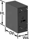
Enclosed Compact Disconnect Switches
Maintained Switch
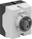 |
Plastic Housing—Their plastic housing protects the switch and resists denting, chipping, and cracking.
Lockout—All switches have a lockout so you can secure them in the off position with a padlock (not included).
IP65 Enclosure Rating—Rated IP65, the housing also seals out water even in frequently washed down areas.
Switching Current @ Voltage | Switch Designation | Electrical Phase (hp) | Ht. | Wd. | For Max. Padlock Shackle Dia. | Enclosure Rating | Certification | Specs. Met | Each | |||
|---|---|---|---|---|---|---|---|---|---|---|---|---|
Yellow Plastic Housing with Red Actuator | ||||||||||||
3 Circuits Controlled with Lockout | ||||||||||||
| 12 amp @ 600V AC, 16 amp @ 24V DC | 3PST | Single (1/2 hp @ 120V AC) Three (1 hp @ 120V AC) Three (3 hp @ 240V AC) | 4 3/4" | 3 13/16" | 5/16" | IP65 | UL Recognized Component, CSA Certified | UL 508 | 65915K21 | 0000000 | ||
| 16 amp @ 600V AC, 20 amp @ 24V DC | 3PST | Single (1 hp @ 120V AC) Three (2 hp @ 120V AC) Three (5 hp @ 240V AC) | 4 3/4" | 3 13/16" | 5/16" | IP65 | UL Recognized Component, CSA Certified | UL 508 | 65915K22 | 000000 | ||
4 Circuits Controlled with Lockout | ||||||||||||
| 12 amp @ 600V AC, 16 amp @ 24V DC | 4PST | Single (1/2 hp @ 120V AC) Three (1 hp @ 120V AC) Three (3 hp @ 240V AC) | 4 3/4" | 3 13/16" | 5/16" | IP65 | UL Recognized Component, CSA Certified | — | 65915K34 | 000000 | ||
| 16 amp @ 600V AC, 20 amp @ 24V DC | 4PST | Single (1 hp @ 120V AC) Three (2 hp @ 120V AC) Three (5 hp @ 240V AC) | 4 3/4" | 3 13/16" | 5/16" | IP65 | UL Recognized Component, CSA Certified | — | 65915K35 | 000000 | ||
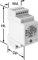
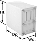
Sequenced Latching Relays
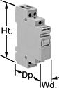 |
These relays switch through a series of different circuit configurations every time they receive an input voltage. The input voltage latches them in position, so they don’t require a constant voltage to stay switched. Use them to control motors, pumps, and lighting. The covered terminals prevent contact with live connections. Mount to 35 mm DIN rail. Also known as step relays.
Switch Starting Position | Input Voltage | Control Power | Switching Current @ Voltage | Max. Switching Voltage, V AC | hp @ Switching Voltage | Ht. | Wd. | Dp. | Each | |||
|---|---|---|---|---|---|---|---|---|---|---|---|---|
1 Circuit Controlled—SPST-NO | ||||||||||||
4 Terminals | ||||||||||||
| 1st Signal—1 Off 2nd Signal—1 On | 24V AC | 6.5 VA | 16 amp @ 120V AC | 277 | 1/2 hp @ 120V AC | 3.3" | 0.7" | 2.4" | 6784T111 | 000000 | ||
| 1st Signal—1 Off 2nd Signal—1 On | 120V AC | 6.5 VA | 16 amp @ 120V AC | 277 | 1/2 hp @ 120V AC | 3.3" | 0.7" | 2.4" | 6784T112 | 00000 | ||
| 1st Signal—1 Off 2nd Signal—1 On | 240V AC | 6.5 VA | 16 amp @ 120V AC | 277 | 1/2 hp @ 120V AC | 3.3" | 0.7" | 2.4" | 6784T113 | 00000 | ||
| 1st Signal—1 Off 2nd Signal—1 On | 12V DC | 5 W | 16 amp @ 120V AC | 277 | 1/2 hp @ 120V AC | 3.3" | 0.7" | 2.4" | 6784T114 | 00000 | ||
| 1st Signal—1 Off 2nd Signal—1 On | 24V DC | 5 W | 16 amp @ 120V AC | 277 | 1/2 hp @ 120V AC | 3.3" | 0.7" | 2.4" | 6784T115 | 00000 | ||
2 Circuits Controlled—DPST-1NO/1NC | ||||||||||||
6 Terminals | ||||||||||||
| 1st Signal—1 Off and 1 On 2nd Signal—1 Off and 1 On | 24V AC | 6.5 VA | 16 amp @ 120V AC | 277 | 1/2 hp @ 120V AC | 3.3" | 0.7" | 2.4" | 6784T131 | 00000 | ||
| 1st Signal—1 Off and 1 On 2nd Signal—1 Off and 1 On | 120V AC | 6.5 VA | 16 amp @ 120V AC | 277 | 1/2 hp @ 120V AC | 3.3" | 0.7" | 2.4" | 6784T132 | 00000 | ||
| 1st Signal—1 Off and 1 On 2nd Signal—1 Off and 1 On | 240V AC | 6.5 VA | 16 amp @ 120V AC | 277 | 1/2 hp @ 120V AC | 3.3" | 0.7" | 2.4" | 6784T133 | 00000 | ||
| 1st Signal—1 Off and 1 On 2nd Signal—1 Off and 1 On | 12V DC | 5 W | 16 amp @ 120V AC | 277 | 1/2 hp @ 120V AC | 3.3" | 0.7" | 2.4" | 6784T134 | 00000 | ||
| 1st Signal—1 Off and 1 On 2nd Signal—1 Off and 1 On | 24V DC | 5 W | 16 amp @ 120V AC | 277 | 1/2 hp @ 120V AC | 3.3" | 0.7" | 2.4" | 6784T135 | 00000 | ||
2 Circuits Controlled—DPST-NO | ||||||||||||
6 Terminals | ||||||||||||
| 1st Signal—2 Off 2nd Signal—1 Off and 1 On 3rd Signal—2 On | 24V AC | 6.5 VA | 16 amp @ 120V AC | 277 | 1/2 hp @ 120V AC | 3.3" | 0.7" | 2.4" | 6784T141 | 00000 | ||
| 1st Signal—2 Off 2nd Signal—1 Off and 1 On 3rd Signal—2 On | 120V AC | 6.5 VA | 16 amp @ 120V AC | 277 | 1/2 hp @ 120V AC | 3.3" | 0.7" | 2.4" | 6784T142 | 00000 | ||
| 1st Signal—2 Off 2nd Signal—1 Off and 1 On 3rd Signal—2 On | 240V AC | 6.5 VA | 16 amp @ 120V AC | 277 | 1/2 hp @ 120V AC | 3.3" | 0.7" | 2.4" | 6784T143 | 00000 | ||
| 1st Signal—2 Off 2nd Signal—1 Off and 1 On 3rd Signal—2 On | 12V DC | 5 W | 16 amp @ 120V AC | 277 | 1/2 hp @ 120V AC | 3.3" | 0.7" | 2.4" | 6784T144 | 00000 | ||
| 1st Signal—2 Off 2nd Signal—1 Off and 1 On 3rd Signal—2 On | 24V DC | 5 W | 16 amp @ 120V AC | 277 | 1/2 hp @ 120V AC | 3.3" | 0.7" | 2.4" | 6784T145 | 00000 | ||
| 1st Signal—2 Off 2nd Signal—2 On | 24V AC | 6.5 VA | 16 amp @ 120V AC | 277 | 1/2 hp @ 120V AC | 3.3" | 0.7" | 2.4" | 6784T121 | 00000 | ||
| 1st Signal—2 Off 2nd Signal—2 On | 120V AC | 6.5 VA | 16 amp @ 120V AC | 277 | 1/2 hp @ 120V AC | 3.3" | 0.7" | 2.4" | 6784T122 | 00000 | ||
| 1st Signal—2 Off 2nd Signal—2 On | 240V AC | 6.5 VA | 16 amp @ 120V AC | 277 | 1/2 hp @ 120V AC | 3.3" | 0.7" | 2.4" | 6784T123 | 00000 | ||
| 1st Signal—2 Off 2nd Signal—2 On | 12V DC | 5 W | 16 amp @ 120V AC | 277 | 1/2 hp @ 120V AC | 3.3" | 0.7" | 2.4" | 6784T124 | 00000 | ||
| 1st Signal—2 Off 2nd Signal—2 On | 24V DC | 5 W | 16 amp @ 120V AC | 277 | 1/2 hp @ 120V AC | 3.3" | 0.7" | 2.4" | 6784T125 | 00000 | ||
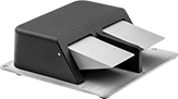
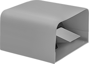
Corrosion-Resistant Washdown Foot Switches
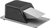 |  |
Style C | Style D |
 | 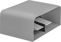 |
Style E | Style F |
1 Speed with Quick-Disconnect Terminals
| |
Style C | Style D |
| |
Style E | Style F |
Foot Switches | Foot Switch Pedals | ||||||||||||||||
|---|---|---|---|---|---|---|---|---|---|---|---|---|---|---|---|---|---|
Mounting | |||||||||||||||||
Style | No. of Circuits Controlled | Switch Starting Position | Switch Action | Switch Designation | Switching Current @ Voltage | No. of Terminals | Quick-Disconnect Tab Wd. | Conduit Trade Size | Fasteners Included | No. of Holes | Hole Dia. | Each | Each | ||||
Aluminum Housing | |||||||||||||||||
| C | 1 | 1 Off or 1 On | Momentary | SPDT | 16 amp @ 125V AC, 250V AC | 3 | 0.187" | 1/2 | No | 4 | 0.28" | 7670K81 | 0000000 | 7670K13 | 00000 | ||
| C | 2 | 2 Off or 2 On | Momentary | DPDT | 16 amp @ 125V AC, 250V AC | 6 | 0.187" | 1/2 | No | 4 | 0.28" | 7670K82 | 000000 | 7670K13 | 0000 | ||
| D | 2 | 1 Off or 1 On | Momentary | SPDT | 16 amp @ 125V AC, 250V AC | 6 | 0.187" | 3/4 | No | 4 | 0.28" | 7670K85 | 000000 | 7670K13 | 0000 | ||
| D | 4 | 2 Off or 2 On | Momentary | DPDT | 16 amp @ 125V AC, 250V AC | 12 | 0.187" | 3/4 | No | 4 | 0.28" | 7670K86 | 000000 | 7670K13 | 0000 | ||
Aluminum Housing with Steel Guard | |||||||||||||||||
| E | 1 | 1 Off or 1 On | Momentary | SPDT | 16 amp @ 125V AC, 250V AC | 3 | 0.187" | 1/2 | No | 4 | 0.28" | 7670K83 | 000000 | 7670K13 | 0000 | ||
| E | 2 | 2 Off or 2 On | Momentary | DPDT | 16 amp @ 125V AC, 250V AC | 6 | 0.187" | 1/2 | No | 4 | 0.28" | 7670K84 | 000000 | 7670K13 | 0000 | ||
| F | 2 | 1 Off or 1 On | Momentary | SPDT | 16 amp @ 125V AC, 250V AC | 6 | 0.187" | 3/4 | No | 4 | 0.28" | 7670K87 | 000000 | 7670K13 | 0000 | ||
| F | 4 | 2 Off or 2 On | Momentary | DPDT | 16 amp @ 125V AC, 250V AC | 12 | 0.187" | 3/4 | No | 4 | 0.28" | 7670K88 | 000000 | 7670K13 | 0000 | ||
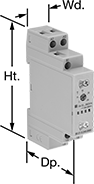
Smart Time and Day Activated Switches
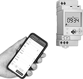 |
Use your smart phone to turn equipment on and off at a set time and day. These switches connect to your phone via NFC (near field communication) and work with a free app to set schedules, adjust settings, and save programs. They can perform a different program each day of the week, and they compensate for leap year and daylight savings time. You can remotely apply programs across compatible switches, so it’s easy to reprogram lighting or equipment in large facilities. These switches mount to a flat surface or attach to DIN rail.
Astronomical Timing—Switches with astronomical timing can be set to turn lights on and off based on sunrise and sunset.
No. of Circuits Controlled | Switching Current @ Voltage | Input Voltage | Max. On/Off Cycles, per wk. | Min. Set Time, min. | Timing Adjustment Style | Switch Designation | Ht. | Wd. | Dp. | Electrical Connection | Operating System Compatibility | For DIN Rail Ht., mm | Wire Connection | Certification | Each | |||
|---|---|---|---|---|---|---|---|---|---|---|---|---|---|---|---|---|---|---|
7-Day Timing Cycle | ||||||||||||||||||
| 1 | 16 amp @ 240V AC | 120V AC/208V AC/240V AC/120V DC/240V DC | 50 | 1 | Joystick | SPDT | 3.4" | 1.4" | 2.2" | NFC | Android 5.1 or Later, iOS 13.1 or Later | 35 | Screw Terminal | UL Listed, C-UL Listed, CE Marked | 7818N101 | 0000000 | ||
| 2 | 16 amp @ 240V AC | 120V AC/208V AC/240V AC/120V DC/240V DC | 50 | 1 | Joystick | DPDT | 3.4" | 1.4" | 2.2" | NFC | Android 5.1 or Later, iOS 13.1 or Later | 35 | Screw Terminal | UL Listed, C-UL Listed, CE Marked | 7818N102 | 000000 | ||
7-Day Timing Cycle—With Astronomical Timing | ||||||||||||||||||
| 1 | 16 amp @ 240V AC | 120V AC/208V AC/240V AC/120V DC/240V DC | 50 | 1 | Joystick | SPDT | 3.4" | 1.4" | 2.2" | NFC | Android 5.1 or Later, iOS 13.1 or Later | 35 | Screw Terminal | UL Listed, C-UL Listed, CE Marked | 7818N103 | 000000 | ||
| 2 | 16 amp @ 240V AC | 120V AC/208V AC/240V AC/120V DC/240V DC | 50 | 1 | Joystick | DPDT | 3.4" | 1.4" | 2.2" | NFC | Android 5.1 or Later, iOS 13.1 or Later | 35 | Screw Terminal | UL Listed, C-UL Listed, CE Marked | 7818N104 | 000000 | ||
DIN-Rail Mount Multifunction Timer Relays
Timer Relays with Delayed, Interval, Switch On, and Repeat Cycles
 |
1 Circuit Controlled |
Timing Range | ||||||||||||||
|---|---|---|---|---|---|---|---|---|---|---|---|---|---|---|
No. of Terminals | Input Voltage | Control Current, mA | Timer Relay Function | No. of | Overall | Switching Current @ Voltage | Max. Switching Voltage, V AC | Ht. | Wd. | Dp. | Each | |||
1 Circuit Controlled with 1 Off or 1 On—SPDT | ||||||||||||||
| 6 | 12V AC, 24V AC, 48V AC, 120V AC, 240V AC, 12V DC, 24V DC, 48V DC, 60V DC, 120V DC, 240V DC | 7 | Delayed Start (Delay on Make) Delayed Switch Off (Delay on Break) Delayed Switch-On with Delayed Switch-Off Interval Switch on (Single Shot) Repeat Cycle | 6 | 0.1 sec. to 24 hr. | 16 amp @ 240V AC | 250 | 3.5" | 0.7" | 2.4" | 6964K4 | 000000 | ||
Timer Relays with Asymmetrical Repeat Cycles
|
1 Circuit Controlled |
Use timer relays with asymmetrical repeat cycles when your repeat cycles have different on- and off-cycle durations.
Asymmetrical-Repeat-Cycle Timer—This function switches the relay on and alternates between different durations of on and off for as long as input voltage is applied. For example, a sprinkler system sprays in short bursts followed by longer rest periods, on and off until input voltage is removed.
Start-Off Asymmetrical Repeat Cycle Timer—This function switches the relay off and alternates between different durations of on and off for as long as input voltage is applied. For example, an irrigation system receives a signal and starts in the off state, allowing water to fill before switching on to start pumping.
Switch-On Asymmetrical Repeat Cycle Timer—This function switches the relay on and alternates between different durations of on and off for as long as input voltage is applied. It requires a switch to activate the timing function instead of the input voltage that’s being applied the entire time. You could use this function to turn on an electric motor for a short period and then turn it off for a longer rest period, repeating that pattern until the switch is turned off.
Switch-Off Asymmetrical Repeat Cycle Timer—This function switches the relay off and alternates between different durations of on and off for as long as input voltage is applied. It requires a switch to activate the timing function instead of input voltage that’s being applied the entire time. It could be used to turn on an electric motor for a short period and then turn it off for a longer rest period, repeating that pattern until the switch is turned off.
Timing Range | ||||||||||||||
|---|---|---|---|---|---|---|---|---|---|---|---|---|---|---|
No. of Terminals | Input Voltage | Control Current, mA | Timer Relay Function | No. of | Overall | Switching Current @ Voltage | Max. Switching Voltage, V AC | Ht. | Wd. | Dp. | Each | |||
1 Circuit Controlled with 1 Off or 1 On—SPDT | ||||||||||||||
| 6 | 12V AC, 24V AC, 48V AC, 120V AC, 240V AC, 12V DC, 24V DC, 48V DC, 60V DC, 120V DC, 240V DC | 7 | Asymmetrical Repeat Cycle Switch-On Asymmetrical Repeat Cycle | 6 | 0.1 sec. to 24 hr. | 16 amp @ 240V AC | 250 | 3.5" | 0.7" | 2.4" | 6964K17 | 000000 | ||
| 8 | 24V AC, 48V AC, 120V AC, 240V AC, 24V DC, 48V DC, 60V DC, 120V DC, 240V DC | 6.2 | Asymmetrical Repeat Cycle Start-Off Asymmetrical Repeat Cycle Switch-On Asymmetrical Repeat Cycle Switch-Off Asymmetrical Repeat Cycle | 8 | 0.05 sec. to 10 day | 16 amp @ 240V AC | 250 | 3.4" | 0.9" | 3.9" | 6964K101 | 00000 | ||
Automatic Transfer Switches for Facility Lights
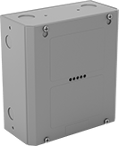 |
Restore lighting immediately during power outages. These switches detect when your main power source goes out and shift your lights to a backup, such as a secondary utility source or generator. To comply with UL 924 and help you meet NFPA standards, they turn your lights on at full brightness even if the lights were turned off or dimmed. You can also wire these switches to your fire alarm. Pull the alarm to activate lights to full brightness during emergencies, even without an outage. All have passed testing to meet UL 1008, a safety standard for transfer switches.
An LED indicator tells you whether lights are running on a primary or backup power source. The indicator also tells you when these switches require maintenance.
Remote Testing Buttons—Add a remote testing button to check if switches behind the wall or ceiling are working properly.
Switches | Remote Testing Buttons | |||||||||||||||||||
|---|---|---|---|---|---|---|---|---|---|---|---|---|---|---|---|---|---|---|---|---|
Switching | Housing | Mounting | ||||||||||||||||||
Current, amp | Voltage, V AC | Switch Designation | Electrical Phase | For No. of Wires | Housing Material | Ht. | Wd. | Dp. | Fasteners Included | No. of Holes | Hole Dia. | Features | Certification | Specs. Met | Each | Each | ||||
NEMA 1 | ||||||||||||||||||||
| 16 | 120 to 277 | DPDT | Single | 4 | Powder-Coated Steel | 8 5/16" | 7 11/16" | 3 15/16" | No | 4 | 1/4" | LED Indicator | ETL Listed, CE Marked | UL 924, UL 1008 | 7934N11 | 0000000 | 8197N11 | 000000 | ||
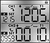
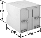
Dual-Channel DIN-Rail Mount Multifunction Timer Relays
 |  |
Timing Range | |||||||||||||||
|---|---|---|---|---|---|---|---|---|---|---|---|---|---|---|---|
No. of Terminals | Input Voltage | Control Current, mA | Timer Relay Function | No. of | Overall | Switching Current @ Voltage | Max. Switching Voltage, V AC | Ht. | Wd. | Dp. | Features | Each | |||
2 Circuits Controlled with 2 Off and 2 On—DPDT | |||||||||||||||
| 12 | 12V AC, 24V AC, 12V DC, 24V DC | 8 | Manual Switch Control Fixed On/Off Switch on (Single Shot) Delayed Start (Delay on Make) Delayed Switch Off (Delay on Break) Delayed Switch-On with Delayed Switch-Off Interval Repeat Cycle Asymmetrical Repeat Cycle Switch-On Asymmetrical Repeat Cycle | 30 | 0.1 sec. to 9,999 hr. | 16 amp @ 240V AC | 240 | 3.4" | 1.4" | 2.2" | 2 Individually Programmable Timers, LCD Screen, Proximity Sensor Compatability (PNP and NPN) | 7105N11 | 0000000 | ||
| 12 | 120V AC, 240V AC, 110V DC, 240V DC | 16 | Manual Switch Control Fixed On/Off Switch on (Single Shot) Delayed Start (Delay on Make) Delayed Switch Off (Delay on Break) Delayed Switch-On with Delayed Switch-Off Interval Repeat Cycle Asymmetrical Repeat Cycle Switch-On Asymmetrical Repeat Cycle | 30 | 0.1 sec. to 9,999 hr. | 16 amp @ 240V AC | 240 | 3.4" | 1.4" | 2.2" | 2 Individually Programmable Timers, LCD Screen | 7105N12 | 000000 | ||
Energy-Saving Motor Starters
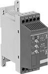 |
Save electricity and extend motor life by reducing the motor's starting current. These starters gradually start and stop motors. Use them on motors where torque varies, such as pumps, compressors, and conveyors. All have an auxiliary contact to send a signal or connect to another device, such as an alarm or indicating light.
Switching | Time, sec. | ||||||||||||||||
|---|---|---|---|---|---|---|---|---|---|---|---|---|---|---|---|---|---|
Full Load Current, amp | Input Voltage, V DC | Voltage, V AC | Current, amp | Electrical Phase (Horsepower @ Switching Voltage) | Accel. | Deceleration | Aux. Contact Switch Starting Position | Ht. | Wd. | Dp. | Mounting Location | For DIN Rail Ht., mm | Certification | Each | |||
| 15 | 24 | 208 to 600 | 16 | Three (5 hp @ 240V AC) Three (10 hp @ 480V AC) | 1 to 20 | 0 to 20 | 1 Off | 5.5" | 1.8" | 4.5" | DIN Rail, Surface | 35 | UL Listed, C-UL Listed, CE Marked | 7112T44 | 0000000 | ||
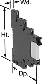
DIN-Rail Mount Interface Relays
1 Circuit Controlled with 1 Off or 1 On—SPDT
 |
With Screw Terminals |
PLC Output Protection—Relays with PLC output protection prevent voltage spikes created by the relay from damaging the output channel on your programmable logic controller (PLC).
Interface Relays | Replacement Relays | ||||||||||||||
|---|---|---|---|---|---|---|---|---|---|---|---|---|---|---|---|
No. of Terminals | Input Voltage | Control Current, mA | Switching Current @ Voltage | Max. Switching Voltage, V AC | hp @ Switching Voltage | Ht. | Wd. | Dp. | Features | Each | Each | ||||
With Screw Terminals | |||||||||||||||
| 5 | 24V AC | 45 | 16 amp @ 240V AC | 250 | 1/3 hp @ 120V AC | 3.3" | 0.6" | 2.7" | LED Indicator, PLC Output Protection | 7098K41 | 000000 | 7098K61 | 00000 | ||
| 5 | 120V AC | 8 | 16 amp @ 240V AC | 250 | 1/3 hp @ 120V AC | 3.3" | 0.6" | 2.7" | LED Indicator, PLC Output Protection | 7098K42 | 00000 | 7098K62 | 00000 | ||
| 5 | 240V AC | 3.5 | 16 amp @ 240V AC | 250 | 1/4 hp @ 120V AC | 3.5" | 0.6" | 3" | LED Indicator | 4144N22 | 00000 | 4026N12 | 0000 | ||
| 5 | 12V DC | 41 | 16 amp @ 240V AC | 250 | 1/4 hp @ 120V AC | 3.5" | 0.6" | 3" | LED Indicator | 4144N11 | 00000 | 4026N11 | 0000 | ||
| 5 | 24V DC | 20 | 16 amp @ 240V AC | 250 | 1/3 hp @ 120V AC | 3.3" | 0.6" | 2.7" | LED Indicator, PLC Output Protection | 7098K43 | 00000 | 7098K63 | 0000 | ||
Hazardous Location Relays
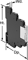 |
Screw Terminals |
Sealed for safety, these relays are a good choice for hazardous locations where combustible or corrosive gases may be present.
Screw Terminals—Relays with screw terminals are considered interface relays, so they’re placed between your controller and components to isolate the input and output circuits. This means they protect your component from voltage spikes while amplifying the relay’s signal and reducing interference for reliable transmission. They are often used for switching applications, such as small motors and pilot lights. The included relay socket mounts on 35 mm DIN rail (also known as DIN 3 rail).
No. of Terminals | Input Voltage | Control Current, mA | Switching Current @ Voltage | Max. Switching Voltage | Ht. | Wd. | Dp. | Enclosure Rating | Hazardous Location Rating | Each | |||
|---|---|---|---|---|---|---|---|---|---|---|---|---|---|
Screw Terminals | |||||||||||||
1 Circuit Controlled with 1 Off or 1 On—SPDT | |||||||||||||
| 5 | 24V AC, 24V DC | 13.5 | 16 amp @ 240V AC/24V DC | 400V AC/300V DC | 3.5" | 0.6" | 2.9" | IP20 | NEC Class I Division 2 Groups A, B, C, D | 4190N15 | 000000 | ||
| 5 | 48V AC, 48V DC | 4 | 16 amp @ 240V AC/24V DC | 400V AC/300V DC | 3.5" | 0.6" | 2.9" | IP20 | NEC Class I Division 2 Groups A, B, C, D | 4190N17 | 00000 | ||
| 5 | 120V AC, 120V DC | 3.5 | 16 amp @ 240V AC/24V DC | 400V AC/300V DC | 3.5" | 0.6" | 2.9" | IP20 | NEC Class I Division 2 Groups A, B, C, D | 4190N19 | 00000 | ||
| 5 | 240V AC, 240V DC | 3.5 | 16 amp @ 240V AC/24V DC | 400V AC/300V DC | 3.5" | 0.6" | 2.9" | IP20 | NEC Class I Division 2 Groups A, B, C, D | 4190N22 | 00000 | ||
Circuit Board Relays
 |  |  |  |
8 Terminals | 5 Terminals | 6 Terminals | 14 Terminals |
No. of Terminals | Input Voltage | Control Current, mA | Switching Current @ Voltage | Max. Switching Voltage, V AC | Mechanical Life Cycles | Ht. | Wd. | Dp. | Pin Lg. | Each | |||
|---|---|---|---|---|---|---|---|---|---|---|---|---|---|
Mechanical Operation | |||||||||||||
1 Circuit Controlled with 1 Off or 1 On—SPDT | |||||||||||||
| 8 | 12V DC | 33 | 16 amp @ 240V AC | 250 | 10,000,000 | 1.1" | 0.5" | 0.6" | 0.1" | 4026N11 | 00000 | ||
| 8 | 110V DC | 4.5 | 16 amp @ 240V AC | 250 | 10,000,000 | 1.1" | 0.5" | 0.6" | 0.1" | 4026N12 | 0000 | ||
