


Choose a switch with the right trigger type, number of inputs, and control functions to power your equipment.
Corrosion-Resistant Washdown Foot Switches
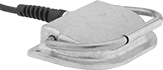
Step on these switches to actuate a process hands-free in an area with frequent washdowns. Rated NEMA 6P, 13, and IP68, they protect against corrosion, washdowns, temporary submersion, and oil/coolant spraying. Made of aluminum, they resist corrosion better than iron and steel switches.
Switches without a guard let you easily see the pedal and step on it from many angles.
Switches | |||||||||||||||
|---|---|---|---|---|---|---|---|---|---|---|---|---|---|---|---|
Wire Leads | Mounting | Replacement Switching Mechanisms | |||||||||||||
| No. of Circuits Controlled | Switch Starting Position | Switch Action | Industry Designation | Switching Current @ Voltage | No. of | Lg., ft. | Conduit Trade Size | Fasteners Included | No. of Holes | Hole Dia. | Each | Each | |||
1 Speed with Wire Leads | |||||||||||||||
Aluminum Housing | |||||||||||||||
| A | 1 | 1 Off (Normally Open) | Springs Back (Momentary) | SPST-NO | 18 A @ 125 V AC/250 V AC | 3 | 8 | 1/2 | No | 2 | 0.25" | 8225K51 | 0000000 | 8225K511 | 000000 |
| Optional Guards | 8225K53 | Each | 000000 |
Safety Relays
Receive signals from safety monitoring relays or controllers to switch devices off and on because of a system failure. Also known as force-guided or mechanically linked contacts, the interlocking opposing contacts on these relays cannot be open or closed at the same time. To keep your system from receiving false switching signals, the interlocking opposing contact must remain open even if a contact welds closed.
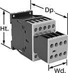
IP20 rated, they have recessed terminals that prevent fingers and other objects from touching live circuits. These relays have been tested to safety standards that can help you achieve your system's PL (performance level) and SIL (safety integrity level). Choose a relay with a PL and SIL rating to meet the needs of your system. Higher ratings indicate greater safety protection. As your system becomes more complex, you generally require a higher safety protection level. Mount them to 35mm DIN rail (also known as DIN 3 Rail).
Relays that meet SIL3 are tested for applications with a probability of failure of 0.01% to 0.1% and are used for preventing fires, explosions, or toxic releases. Relays that meet CAT 4 withstand circuit surges in electrical applications up to 600V.
When a failure is detected, relays with self-monitoring circuitry signal the controller to remove power and prevent restarting until the issue is resolved.
Relays with nondetachable contacts have auxiliary contacts that won’t separate from the relay if there is shock or vibration. Relays with mirror auxiliary contacts have contacts that are normally closed and cannot be open at the same time as a normally open main contact.
hp @ Switching Voltage | |||||||||||||
|---|---|---|---|---|---|---|---|---|---|---|---|---|---|
| Number of Terminals | Input Voltage | Control Current, mA | Switching Current @ Voltage | Max. Switching Voltage | Single Phase | Three Phase | Auxiliary Contact Switch Starting Position | Ht. | Wd. | Dp. | Features | Each | |
With Screw Terminals—DIN-Rail and Surface Mount | |||||||||||||
3 Circuits Controlled with 3 Off (Normally Open)—3PST-NO | |||||||||||||
| 18 | 120V AC | 5 | 18 A @ 400 V AC | 600V AC | 2 hp @ 120 V AC 3 hp @ 240 V AC | 5 hp @ 240 V AC 10 hp @ 480 V AC 15 hp @ 600 V AC | 2 Off (Normally Open) or 3 On (Normally Closed) | 3.4" | 1.8" | 5.5" | Interlocked Opposing Contacts, Recessed Terminals, Self-Monitoring Circuitry, Nondetachable Auxiliary Contacts, Mirror Auxiliary Contacts, Inspection Window | 6242N14 | 0000000 |
| 18 | 24V DC | 3 | 18 A @ 400 V AC | 600V AC | 2 hp @ 120 V AC 3 hp @ 240 V AC | 5 hp @ 240 V AC 10 hp @ 480 V AC 15 hp @ 600 V AC | 2 Off (Normally Open) or 3 On (Normally Closed) | 3.4" | 1.8" | 5.5" | Interlocked Opposing Contacts, Recessed Terminals, Self-Monitoring Circuitry, Nondetachable Auxiliary Contacts, Mirror Auxiliary Contacts, Inspection Window | 6242N18 | 000000 |