Filter by
Actuator Style


Switching Voltage

Switch Action
Switching Current
Push-Button Style

Switch Designation
Wire Connection
Enclosure Rating
Switch Starting Position
Push-Button Shape


Housing Material
Illumination


Export Control Classification Number (ECCN)
DFARS Specialty Metals
Metal 22 mm Panel-Mount Push-Button Switches
Round Push-Button with Quick-Disconnect-Terminal Wire Connection—Not Illuminated (250V AC /250V DC Maximum Voltage)
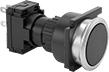 |
Flush with Quick-Disconnect-Terminal Wire Connection |
IP65 Enclosure Rating—NEMA 4, IP65, and IP66 rated switches seal out water from washdowns.
No. of Circuits Controlled | Switch Starting Position | Switch Action | No. of Terminals | Switch Designation | Switching Current @ Voltage | Dia. | For Max. No. of Contact Blocks | Actuator Color | Enclosure Rating | Each | |||
|---|---|---|---|---|---|---|---|---|---|---|---|---|---|
Flush Push Button | |||||||||||||
| 1 | 1 Off | Momentary | 2 | SPST-NO | 2.5 amp @ 125V AC, 0.15 amp @ 250V DC | 1" | 3 | Black | IP65 | 8382K105 | 000000 | ||
| 1 | 1 Off | Maintained | 2 | SPST-NO | 2.5 amp @ 125V AC, 0.15 amp @ 250V DC | 1" | 3 | Black | IP65 | 8382K104 | 00000 | ||
| 1 | 1 On | Momentary | 2 | SPST-NC | 2.5 amp @ 125V AC, 0.15 amp @ 250V DC | 1" | 3 | Black | IP65 | 8382K102 | 00000 | ||
| 1 | 1 On | Maintained | 2 | SPST-NC | 2.5 amp @ 125V AC, 0.15 amp @ 250V DC | 1" | 3 | Black | IP65 | 8382K103 | 00000 | ||
| 2 | 1 Off and 1 On | Momentary | 4 | DPST-1NO/1NC | 2.5 amp @ 125V AC, 0.15 amp @ 250V DC | 1" | 3 | Black | IP65 | 8382K101 | 00000 | ||
 |
Make or break an electrical circuit. These contact blocks mount to manual switches and transmit an electrical signal when the switch actuator is engaged. You can stack multiple blocks, so a single switch can control several circuits. This is helpful in setups that require multiple systems to turn on or off at the same time. For example, the switch on a conveyor line could turn off the conveyor and turn on a diverter and alarm.
Additional contact blocks can be added to control more circuits, or replace the included contact block.
No. of Circuits Controlled | Switch Starting Position | No. of Terminals | Switch Designation | Switching Current @ Voltage | For Switch Manufacturer | Max. Voltage | Wire Connection | Certification | Specs. Met | Each | ||
|---|---|---|---|---|---|---|---|---|---|---|---|---|
| 1 | 1 Off | 2 | SPST-NO | 2.5 amp @ 125V AC, 0.15 amp @ 250V DC | EAO | 250V AC/250V DC | Quick-Disconnect Terminal | CE Marked, CSA Certified | EN 60947-5-1, IEC 60947-5-1 | 8008N22 | 000000 | |
| 1 | 1 On | 2 | SPST-NC | 2.5 amp @ 125V AC, 0.15 amp @ 250V DC | EAO | 250V AC/250V DC | Quick-Disconnect Terminal | CE Marked, CSA Certified | EN 60947-5-1, IEC 60947-5-1 | 8008N21 | 00000 | |
| 2 | 1 Off and 1 On | 4 | DPST-1NO/1NC | 2.5 amp @ 125V AC, 0.15 amp @ 250V DC | EAO | 250V AC/250V DC | Quick-Disconnect Terminal | CE Marked, CSA Certified | EN 60947-5-1, IEC 60947-5-1 | 8008N19 | 00000 |
Switch Contact Blocks
 |
Make or break an electrical circuit. These contact blocks mount to manual switches and transmit an electrical signal when the switch actuator is engaged. You can stack multiple blocks, so a single switch can control several circuits. This is helpful in setups that require multiple systems to turn on or off at the same time. For example, the switch on a conveyor line could turn off the conveyor and turn on a diverter and alarm.
No. of Circuits Controlled | Switch Starting Position | No. of Terminals | Switch Designation | Wire Connection | Enclosure Rating | For Switch Manufacturer Series | Each | |||
|---|---|---|---|---|---|---|---|---|---|---|
EAO | ||||||||||
| 1 | 1 Off | 2 | SPST-NO | Quick-Disconnect Terminal | — | 61 | 8008N22 | 000000 | ||
| 1 | 1 On | 2 | SPST-NC | Quick-Disconnect Terminal | — | 61 | 8008N21 | 00000 | ||
| 2 | 1 Off and 1 On | 4 | DPST-1NO/1NC | Quick-Disconnect Terminal | — | 61 | 8008N19 | 00000 | ||
Schneider Electric | ||||||||||
| 1 | 1 Off | 2 | SPST-NO | Screw Terminal | IP20 | XB5 | 8008N11 | 00000 | ||
| 1 | 1 On | 2 | SPST-NC | Screw Terminal | IP20 | XB5 | 8008N12 | 00000 | ||
Limit Switches
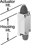 | 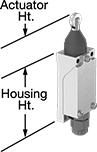 |
Style A | Style B |
 |  |
Style D | Style E |
 |  |
Style G | M12 Connection |
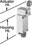
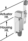
When a moving object contacts the actuator on these switches, they open or close a circuit. They have the rapid-closing action of a snap-acting switch, but with a larger actuator. This makes them a good choice for use with large objects—for instance, a box on a conveyor runs into the switch, stopping the conveyor.
Plunger Actuator—Switches with a plunger actuator require a push to actuate, similar to a button.
Roller Plunger Actuator—Switches with a roller plunger actuator have a roller that moves when an object pushes the actuator. This reduces friction during actuation to limit wear and tear on your switch.
Roller Lever Actuator—Switches with a roller lever actuator use a lever with a roller at the end to activate. This allows parts to glide across the actuation surface with minimal friction, limiting wear and tear on your switch.
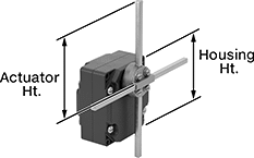
T-Rod Actuator—Switches with a T-rod actuator have four rods extending in different directions from a pivot point. If an object contacts any of the rods from any direction, these switches actuate. Since they have such a large actuation area, they’re great for detecting moving parts when your machine tool isn’t perfectly aligned.
4-Pole M12 Connection—Switches with a 4-pole M12 plug connect to cords with a socket (sold separately), allowing you to quickly connect and disconnect the switch.
Style E—Styles E and F let you adjust the actuator’s height to align it with your target.
IP67 Enclosure Rating—Switches rated IP67 are protected against dust and temporary submersion.
Switches | Cords | ||||||||||||||||||||
|---|---|---|---|---|---|---|---|---|---|---|---|---|---|---|---|---|---|---|---|---|---|
Housing | |||||||||||||||||||||
Style | No. of Circuits Controlled | Switch Starting Position | Switch Action | Switch Designation | Switching Current @ Voltage | Max. Voltage | Operating Temp. Range, ° F | Actuator Ht. | No. of Terminals | Lg. | Ht. | Dp. | Housing Material | Conduit Thread Size | Enclosure Rating | Each | Each | ||||
Plunger Actuator | |||||||||||||||||||||
4-Pole M12 Connection | |||||||||||||||||||||
| A | 1 | 1 Off or 1 On | Momentary | SPDT | 3 amp @ 250V AC, 10 amp @ 250V DC | 250V AC 250V DC | -22 to 158 | 0.8" | — | 1.1" | 2.5" | 1.2" | Plastic | — | IP67 | 7988K101 | 000000 | 7628K99 | 000000 | ||
Roller Plunger Actuator | |||||||||||||||||||||
4-Pole M12 Connection | |||||||||||||||||||||
| B | 1 | 1 Off or 1 On | Momentary | SPDT | 3 amp @ 250V AC, 10 amp @ 250V DC | 250V AC 250V DC | -22 to 158 | 1.2" | — | 1.1" | 2.5" | 1.2" | Plastic | — | IP67 | 7988K102 | 00000 | 7628K99 | 00000 | ||
Roller Lever Actuator | |||||||||||||||||||||
4-Pole M12 Connection | |||||||||||||||||||||
| D | 1 | 1 Off or 1 On | Momentary | SPDT | 3 amp @ 250V AC, 10 amp @ 250V DC | 250V AC 250V DC | -22 to 158 | 1.5" | — | 1.1" | 2.5" | 1.2" | Plastic | — | IP67 | 7988K103 | 00000 | 7628K99 | 00000 | ||
| E | 1 | 1 Off or 1 On | Momentary | SPDT | 3 amp @ 250V AC, 10 amp @ 250V DC | 250V AC 250V DC | -22 to 158 | 1.5" to 3.3" | — | 1.1" | 2.5" | 1.2" | Plastic | — | IP67 | 7988K104 | 000000 | 7628K99 | 00000 | ||
T-Rod Actuator | |||||||||||||||||||||
Screw-Terminal Wire Connection | |||||||||||||||||||||
| G | 2 | 2 Off or 2 On | Maintained | DPDT | 10 amp @ 240V AC, 0.27 amp @ 250V DC | 240V AC 250V DC | -13 to 158 | 7.9" | 8 | 3.4" | 3.7" | 2.1" | Zinc | PG-13.5 | IP54 | 7988K106 | 000000 | ——— | 0 | ||
Durable Disconnect Switches
Maintained Switch%20--%3e%3csvg%20version='1.1'%20id='Layer_1'%20xmlns='http://www.w3.org/2000/svg'%20xmlns:xlink='http://www.w3.org/1999/xlink'%20x='0px'%20y='0px'%20viewBox='0%200%20400%20400'%20style='enable-background:new%200%200%20400%20400;'%20xml:space='preserve'%3e%3cstyle%20type='text/css'%3e%20.st0{fill:%231A70A0;}%20.st1{opacity:0.5;}%20%3c/style%3e%3cg%3e%3cg%3e%3cpath%20class='st0'%20d='M200,56.9c38.35,0,74.4,14.93,101.51,42.05c27.11,27.11,42.05,63.17,42.05,101.51s-14.93,74.4-42.05,101.51%20S238.35,344.02,200,344.02s-74.4-14.93-101.51-42.05c-27.11-27.11-42.05-63.17-42.05-101.51s14.93-74.4,42.05-101.51%20S161.65,56.9,200,56.9%20M200,12.9C96.41,12.9,12.44,96.88,12.44,200.46c0,103.59,83.97,187.56,187.56,187.56%20c103.59,0,187.56-83.97,187.56-187.56C387.56,96.88,303.59,12.9,200,12.9L200,12.9z'/%3e%3c/g%3e%3cg%3e%3cg%20class='st1'%3e%3cpath%20class='st0'%20d='M235.49,152.24h16.15l-27.46,111.87c-1.94,7.8-2.91,12.5-2.91,14.1c0,1.82,0.58,3.29,1.73,4.41%20c1.16,1.12,2.69,1.68,4.61,1.68c5.23,0,11.78-3.85,19.63-11.55l17.22,21.34c-16.95,17.33-34.87,26-53.78,26%20c-8.37,0-15.45-1.47-21.23-4.41c-5.79-2.94-10.44-7.25-13.95-12.92c-3.51-5.67-5.27-11.18-5.27-16.53c0-1.93,0.35-5.24,1.05-9.94%20c1-6.94,2.05-12.54,3.15-16.82l15.22-62.15h-32.69l7.65-30.97C190.89,163.58,214.53,158.88,235.49,152.24z%20M230.44,80.84%20c8.24,0,14.66,2.62,19.26,7.86c4.6,5.24,6.9,11.55,6.9,18.94c0,5.46-1.42,10.7-4.25,15.73c-2.83,5.03-6.88,9.07-12.12,12.12%20c-5.24,3.05-10.33,4.57-15.24,4.57c-4.6,0-9.17-1.23-13.72-3.69c-4.55-2.46-8.02-5.78-10.43-9.95%20c-2.41-4.17-3.61-8.67-3.61-13.48c0-5.35,1.52-10.64,4.57-15.89c3.05-5.24,7.03-9.25,11.96-12.04%20C218.68,82.23,224.24,80.84,230.44,80.84z'/%3e%3c/g%3e%3cg%3e%3cpath%20class='st0'%20d='M214.08,152.24h16.15l-27.46,111.87c-1.94,7.8-2.91,12.5-2.91,14.1c0,1.82,0.58,3.29,1.73,4.41%20c1.16,1.12,2.69,1.68,4.61,1.68c5.23,0,11.78-3.85,19.63-11.55l17.22,21.34c-16.95,17.33-34.87,26-53.78,26%20c-8.37,0-15.45-1.47-21.23-4.41c-5.79-2.94-10.44-7.25-13.95-12.92c-3.51-5.67-5.27-11.18-5.27-16.53c0-1.93,0.35-5.24,1.05-9.94%20c1-6.94,2.05-12.54,3.15-16.82l15.22-62.15h-32.69l7.65-30.97C169.48,163.58,193.11,158.88,214.08,152.24z%20M209.03,80.84%20c8.24,0,14.66,2.62,19.26,7.86c4.6,5.24,6.9,11.55,6.9,18.94c0,5.46-1.42,10.7-4.25,15.73c-2.83,5.03-6.88,9.07-12.12,12.12%20c-5.24,3.05-10.33,4.57-15.24,4.57c-4.6,0-9.17-1.23-13.72-3.69c-4.55-2.46-8.02-5.78-10.43-9.95%20c-2.41-4.17-3.61-8.67-3.61-13.48c0-5.35,1.52-10.64,4.57-15.89c3.05-5.24,7.03-9.25,11.96-12.04%20C197.26,82.23,202.83,80.84,209.03,80.84z'/%3e%3c/g%3e%3c/g%3e%3c/g%3e%3c/svg%3e)
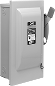 |
Fuse Holder—Switches with a fuse holder are used where overload protection is needed. When the current exceeds the fuse’s rating, the fuse will blow, interrupting the circuit to prevent the switch from overheating, breaking, or causing a fire. These switches require rejection-style fuse clips when used with UL Class RK1, RK5, or T fuses. Note: Horsepower ratings are based on time-delay fuses installed.
Safety Interlock—Switches with safety interlock keep the door closed when the switch is on and prevent the switch from turning on when the door is open.
Switches | Rejection-Style Fuse Clips for RK1 and RK5 Fuse Class | ||||||||||||||||
|---|---|---|---|---|---|---|---|---|---|---|---|---|---|---|---|---|---|
Switching | |||||||||||||||||
Current, amp | Voltage | Switch Designation | Electrical Phase (hp) | For No. of Wires | For Fuse UL Class | Ht. | Wd. | For Max. Padlock Shackle Dia. | Wire Connection | Enclosure Rating | Certification | Each | Each | ||||
Gray Powder-Coated Steel Housing with Red Actuator | |||||||||||||||||
2 Circuits Controlled with Lockout, Safety Interlock, and Fuse Holder | |||||||||||||||||
| 30 | 240V AC/250V DC | DPST | Single (3 hp @ 240V AC) Three (7 1/2 hp @ 240V AC) | 3 | RK1, RK5, K5, H | 14 1/4" | 6 5/8" | 5/16" | Tab | NEMA 1 | UL Listed | 7524K21 | 0000000 | 7524K414 | 000000 | ||
| 100 | 240V AC/250V DC | DPST | Single (15 hp @ 240V AC) | 3 | RK1, RK5, K5, T, H | 17 1/2" | 11 3/16" | 5/16" | Tab | NEMA 1 | UL Listed | 7524K23 | 000000 | 7524K413 | 00000 | ||
2 Circuits Controlled with Lockout and Fuse Holder | |||||||||||||||||
| 60 | 240V AC/250V DC | DPST | Single (10 hp @ 240V AC) | 3 | RK1, RK5, K5, H | 10 1/16" | 6 7/16" | 5/16" | Tab | NEMA 1 | UL Listed | 7524K22 | 000000 | 7524K412 | 00000 | ||
3 Circuits Controlled with Lockout and Safety Interlock | |||||||||||||||||
| 100 | 240V AC/250V DC | 3PST | Single (15 hp @ 240V AC) Three (30 hp @ 240V AC) | 3 | — | 17 1/2" | 10 3/16" | 5/16" | Tab | NEMA 1 | UL Listed | 7524K33 | 000000 | ——— | 0 | ||
3 Circuits Controlled with Lockout, Safety Interlock, and Fuse Holder | |||||||||||||||||
| 30 | 240V AC/250V DC | 3PST | Single (3 hp @ 240V AC) Three (7 1/2 hp @ 240V AC) | 3 | RK1, RK5, K5, H | 14 1/4" | 6 5/8" | 5/16" | Tab | NEMA 1 | UL Listed | 7524K11 | 000000 | 7524K414 | 00000 | ||
| 100 | 240V AC/250V DC | 3PST | Single (15 hp @ 240V AC) Three (30 hp @ 240V AC) | 4 | RK1, RK5, K5, T, H | 23 1/8" | 11 3/4" | 5/16" | Tab | NEMA 1 | UL Listed | 7524K13 | 000000 | 7524K413 | 00000 | ||
3 Circuits Controlled with Lockout and Fuse Holder | |||||||||||||||||
| 60 | 240V AC/250V DC | 3PST | Single (10 hp @ 240V AC) Three (15 hp @ 240V AC) | 4 | RK1, RK5, K5, H | 10 1/16" | 6 7/16" | 5/16" | Tab | NEMA 1 | UL Listed | 7524K12 | 000000 | 7524K412 | 00000 | ||
3 Circuits Controlled with Lockout | |||||||||||||||||
| 30 | 240V AC/250V DC | 3PST | Single (3 hp @ 240V AC) Three (7 1/2 hp @ 240V AC) | 3 | — | 6 3/8" | 4 9/16" | 5/16" | Tab | NEMA 1 | UL Listed | 7524K31 | 00000 | ——— | 0 | ||
| 60 | 240V AC/250V DC | 3PST | Three (15 hp @ 240V AC) | 3 | — | 8 9/16" | 5 7/16" | 5/16" | Tab | NEMA 1 | UL Listed | 7524K32 | 000000 | ——— | 0 | ||
Compact Safety Limit Switches
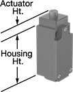 | 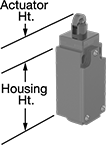 | 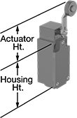 |
Style A | Style B | Style D |
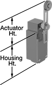 |  |  |
Style E | Style F | Style G |
Shorter and thinner than other safety limit switches, these are sized to fit tight spaces. They protect machinery and ensure the safety of personnel. Positive-force contacts open the circuit when actuated, even if a spring fails or the contacts stick. They send a signal to your circuit when an object hits the actuator—for instance, a box on a conveyor runs into the switch, stopping the conveyor. They open and close circuits as fast as snap-acting switches, but they have a bigger actuator for large objects. All are NEMA and IP rated for protection from washdowns.
Plunger Actuator—Switches with a plunger actuator require a push to actuate, similar to a button.
Roller Plunger Actuator—Switches with a roller plunger actuator have a roller that moves parallel to the mounting direction when an object pushes the actuator. This reduces friction during actuation to limit wear and tear on your switch.
Roller Lever Actuator—Switches with a roller lever actuator use a lever with a roller at the end to activate. This allows parts to glide across the actuation surface with minimal friction, limiting wear and tear.
Rod Actuator—Switches with a rod actuator have a large actuation area with a rod extending out of the actuator’s body. They’re best where the object actuating the switch is far away.
Wobble Stick Actuator—Switches with a wobble stick actuator have an arm that rotates 360°, so you don’t need to align it in a specific direction. The actuator won’t snap if pushed backward, such as if there’s a jam in your system.
Styles E and F—Styles E and F have an actuator that allows you to adjust its height, making it easier to align the switch with the target during installation.
NEMA 13 Enclosure Rating and IP67 Enclosure Rating—NEMA 13 and IP67 rated switches are protected from oil/coolant spraying and temporary submersion.
Housing | ||||||||||||||||||||
|---|---|---|---|---|---|---|---|---|---|---|---|---|---|---|---|---|---|---|---|---|
Style | No. of Circuits Controlled | Switch Starting Position | Switch Action | Switch Designation | Switching Current @ Voltage | Max. Voltage | Actuation Torque, in·ozf | Operating Temp. Range, ° F | Actuator Ht. | No. of Terminals | Lg. | Ht. | Dp. | Housing Material | Conduit Trade Size | Enclosure Rating | Each | |||
Plunger Actuator | ||||||||||||||||||||
Screw-Terminal Wire Connection | ||||||||||||||||||||
| A | 1 | 1 Off or 1 On | Momentary | SPDT | 3 amp @ 240V AC, 0.27 amp @ 250V DC | 240V AC 250V DC | — | -40 to 185 | 0.7" | 4 | 1.2" | 2.6" | 1.2" | Plastic | 1/2 | NEMA 4X, NEMA 13, IP66, IP67 | 6352K201 | 000000 | ||
| A | 1 | 1 Off or 1 On | Momentary | SPDT | 10 amp @ 300V AC, 10 amp @ 250V DC | 300V AC 250V DC | — | -40 to 185 | 0.7" | 4 | 1.2" | 2.6" | 1.2" | Zinc | 1/2 | NEMA 4, NEMA 13, IP66, IP67 | 6352K41 | 00000 | ||
Roller Plunger Actuator | ||||||||||||||||||||
Screw-Terminal Wire Connection | ||||||||||||||||||||
| B | 1 | 1 Off or 1 On | Momentary | SPDT | 3 amp @ 240V AC, 0.27 amp @ 250V DC | 240V AC 250V DC | — | -40 to 185 | 1.1" | 4 | 1.2" | 2.6" | 1.2" | Plastic | 1/2 | NEMA 4X, NEMA 13, IP66, IP67 | 6352K202 | 00000 | ||
| B | 1 | 1 Off or 1 On | Momentary | SPDT | 10 amp @ 300V AC, 10 amp @ 250V DC | 300V AC 250V DC | — | -40 to 185 | 1.1" | 4 | 1.2" | 2.6" | 1.2" | Zinc | 1/2 | NEMA 4, NEMA 13, IP66, IP67 | 6352K42 | 000000 | ||
Roller Lever Actuator | ||||||||||||||||||||
Screw-Terminal Wire Connection | ||||||||||||||||||||
| D | 1 | 1 Off or 1 On | Momentary | SPDT | 3 amp @ 240V AC, 0.27 amp @ 250V DC | 240V AC 250V DC | 17.6 | -40 to 185 | 2" | 4 | 1.2" | 2.6" | 1.2" | Plastic | 1/2 | NEMA 4X, NEMA 13, IP66, IP67 | 6352K203 | 00000 | ||
| D | 1 | 1 Off or 1 On | Momentary | SPDT | 10 amp @ 300V AC, 10 amp @ 250V DC | 300V AC 250V DC | 17.6 | -40 to 185 | 2.1" | 4 | 1.2" | 2.6" | 1.2" | Zinc | 1/2 | NEMA 4, NEMA 13, IP66, IP67 | 6352K43 | 000000 | ||
| E | 1 | 1 Off or 1 On | Momentary | SPDT | 3 amp @ 240V AC, 0.27 amp @ 250V DC | 240V AC 250V DC | 17.6 | -40 to 185 | 1.6" to 3.3" | 4 | 1.2" | 2.6" | 1.2" | Plastic | 1/2 | NEMA 4X, NEMA 13, IP66, IP67 | 6352K204 | 00000 | ||
| E | 1 | 1 Off or 1 On | Momentary | SPDT | 10 amp @ 300V AC, 10 amp @ 250V DC | 300V AC 250V DC | 17.6 | -40 to 185 | 1.6" to 3.3" | 4 | 1.2" | 2.6" | 1.2" | Zinc | 1/2 | NEMA 4, NEMA 13, IP66, IP67 | 6352K44 | 000000 | ||
Rod Actuator | ||||||||||||||||||||
Screw-Terminal Wire Connection | ||||||||||||||||||||
| F | 1 | 1 Off or 1 On | Momentary | SPDT | 10 amp @ 600V AC, 10 amp @ 250V DC | 600V AC 250V DC | 17.6 | -40 to 185 | 0.6" to 5.8" | 4 | 1.2" | 2.4" | 1.2" | Plastic | 1/2 | NEMA 4, NEMA 13, IP66, IP67 | 65745K18 | 00000 | ||
Wobble Stick Actuator | ||||||||||||||||||||
Screw-Terminal Wire Connection | ||||||||||||||||||||
| G | 1 | 1 Off or 1 On | Momentary | SPDT | 3 amp @ 240V AC, 0.27 amp @ 250V DC | 240V AC 250V DC | — | -40 to 185 | 4.9" | 4 | 1.2" | 2.4" | 1.2" | Plastic | 1/2 | NEMA 4X, NEMA 13, IP66, IP67 | 6352K205 | 000000 | ||
Safety Limit Switches
 |  |  |
Style A | Style B | Style C |
 |  |  |
Style D | Style E | Style G |
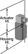
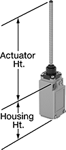
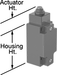
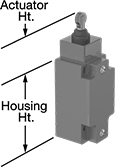
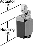
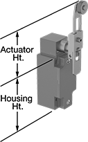
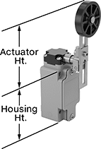
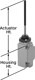
Protect machinery and ensure the safety of personnel—these switches have positive-force contacts that will open the circuit when actuated even if a spring fails or the contacts stick. When an object in motion comes into contact with the actuator, it sends a signal to open or close a circuit. These switches have the rapid-closing action of a snap-acting switch, but with a larger actuator. This makes them a good choice for use with large objects—for instance, a box on a conveyor runs into the switch, stopping the conveyor.
Plunger Actuator—Switches with a plunger actuator require a push to actuate, similar to a button.
Roller Plunger Actuator—Switches with a roller plunger actuator have a roller that moves parallel to the mounting direction when an object pushes the actuator. This reduces friction during actuation to limit wear and tear on your switch.
Roller Lever Actuator—Switches with a roller lever actuator use a lever with a roller at the end to activate. This allows parts to glide across the actuation surface with minimal friction, limiting wear and tear on your switch.
Wobble Stick Actuator—Switches with a wobble stick actuator have an arm that rotates 360°, so you don’t need to align it in a specific direction. Since the actuator is flexible, it won’t snap if pushed backward. That makes these switches a great choice for systems that get jammed often.
Styles D and E—Styles D, E, and F have an actuator that allows you to adjust its height, making it easier to align switch with the target during installation.
Plastic Actuator—Switches with a plastic actuator limit wear and tear on passing objects better than switches with a steel actuator.
Steel Actuator—Switches with a steel actuator are more durable than switches with a plastic actuator. They also handle higher loads.
Housing | |||||||||||||||||||||
|---|---|---|---|---|---|---|---|---|---|---|---|---|---|---|---|---|---|---|---|---|---|
Style | No. of Circuits Controlled | Switch Starting Position | Switch Action | Switch Designation | Actuator Material | Switching Current @ Voltage | Max. Voltage | Actuation Torque, in·ozf | Operating Temp. Range, ° F | Actuator Ht. | No. of Terminals | Lg. | Ht. | Dp. | Housing Material | Conduit Trade Size | Enclosure Rating | Each | |||
Plunger Actuator | |||||||||||||||||||||
Screw-Terminal Wire Connection | |||||||||||||||||||||
| A | 1 | 1 Off or 1 On | Momentary | SPDT | Steel | 10 amp @ 600V AC, 10 amp @ 250V DC | 600V AC 250V DC | — | -13 to 185 | 1.3" | 5 | 1.7" | 3.2" | 1.7" | Zinc | 1/2 | NEMA 4, NEMA 13, IP67 | 6352K54 | 0000000 | ||
Roller Plunger Actuator | |||||||||||||||||||||
Screw-Terminal Wire Connection | |||||||||||||||||||||
| B | 1 | 1 Off or 1 On | Momentary | SPDT | Steel | 10 amp @ 600V AC, 10 amp @ 250V DC | 600V AC 250V DC | — | -13 to 185 | 1.8" | 5 | 1.7" | 3.2" | 1.7" | Zinc | 1/2 | NEMA 4, NEMA 13, IP67 | 6352K55 | 000000 | ||
Roller Lever Actuator | |||||||||||||||||||||
Screw-Terminal Wire Connection | |||||||||||||||||||||
| C | 1 | 1 Off or 1 On | Momentary | SPDT | Plastic | 10 amp @ 600V AC, 10 amp @ 250V DC | 600V AC 250V DC | — | -13 to 185 | 2.3" | 5 | 1.7" | 3.2" | 1.7" | Zinc | 1/2 | NEMA 4, NEMA 13, IP67 | 6352K101 | 000000 | ||
| D | 1 | 1 Off or 1 On | Momentary | SPDT | Plastic | 10 amp @ 600V AC, 10 amp @ 250V DC | 600V AC 250V DC | 46.4 | -40 to 185 | 2.1" to 4.2" | 5 | 1.7" | 3.2" | 1.7" | Zinc | 1/2 | NEMA 4, NEMA 13, IP67 | 6352K57 | 000000 | ||
| D | 1 | 1 Off or 1 On | Momentary | SPDT | Steel | 10 amp @ 600V AC, 10 amp @ 250V DC | 600V AC 250V DC | — | -40 to 185 | 2.5" to 4.5" | 5 | 1.7" | 3.2" | 1.7" | Zinc | 1/2 | NEMA 4, NEMA 13, IP67 | 6352K104 | 000000 | ||
| E | 1 | 1 Off or 1 On | Momentary | SPDT | Plastic | 10 amp @ 600V AC, 10 amp @ 250V DC | 600V AC 250V DC | — | -40 to 185 | 3.1" to 5.1" | 5 | 1.7" | 3.2" | 1.7" | Zinc | 1/2 | NEMA 4, NEMA 13, IP67 | 6352K105 | 000000 | ||
Wobble Stick Actuator | |||||||||||||||||||||
Screw-Terminal Wire Connection | |||||||||||||||||||||
| G | 1 | 1 Off or 1 On | Momentary | SPDT | Plastic | 10 amp @ 600V AC, 10 amp @ 250V DC | 600V AC 250V DC | — | -13 to 185 | 5.7" | 5 | 1.7" | 3.2" | 1.7" | Zinc | 1/2 | NEMA 4, NEMA 13, IP67 | 6352K102 | 000000 | ||
| G | 1 | 1 Off or 1 On | Momentary | SPDT | Steel | 10 amp @ 600V AC, 10 amp @ 250V DC | 600V AC 250V DC | — | -13 to 185 | 5.3" | 5 | 1.7" | 3.2" | 1.7" | Zinc | 1/2 | NEMA 4, NEMA 13, IP67 | 6352K103 | 000000 | ||
Wet-Location Foot Switches
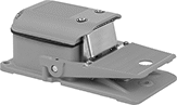 | 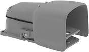 |
Switch | Switch with Guard |
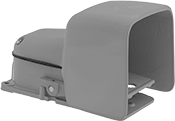 | 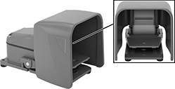 |
Switch with Oversized Guard | Switch with Safety Lever and Oversized Guard |
Operate these switches hands-free when working in wet or humid environments. They’re IP and NEMA rated, so they won’t corrode when exposed to water, oil, or coolant spray.
Oversized Guard—Switches with an oversized guard fit bulky shoes and toe guards.
Safety Lever—Switches with a safety lever lock the pedal in place to prevent accidental activation. Fully insert your foot to release the safety lever. If the lever isn't released, the pedal won't depress.
With Guard—Switches with a guard shield the pedal so you don't accidentally step on it and activate the switch.
Without Guard—Switches without a guard are unobstructed and let you press them from multiple angles.
2 Speeds—Two-speed switches have two contact points. Push the pedal halfway down for the slow speed or all the way down for the high speed.
Number of | Mounting | ||||||||||||||
|---|---|---|---|---|---|---|---|---|---|---|---|---|---|---|---|
Speeds | Circuits Controlled | Switch Starting Position | Switch Action | Switch Designation | Switching Current @ Voltage | Wire Connection | No. of Terminals | Conduit Trade Size | Fasteners Included | No. of Holes | Hole Dia. | Each | |||
Iron Housing | |||||||||||||||
IP56, NEMA 4, NEMA 13 | |||||||||||||||
| 1 | 1 | 1 Off or 1 On | Momentary | SPDT | 20 amp @ 125V AC, 250V AC, 0.5 amp @ 125V DC, 0.25 amp @ 250V DC | Screw Terminal | 3 | 3/4 | No | 3 | 0.31" | 7372K101 | 0000000 | ||
| 1 | 1 | 1 Off or 1 On | Maintained | SPDT | 20 amp @ 125V AC, 250V AC, 0.5 amp @ 125V DC, 0.25 amp @ 250V DC | Screw Terminal | 3 | 3/4 | No | 3 | 0.31" | 7372K102 | 000000 | ||
| 1 | 2 | 2 Off or 2 On | Momentary | DPDT | 20 amp @ 125V AC, 250V AC, 0.5 amp @ 125V DC, 0.25 amp @ 250V DC | Screw Terminal | 6 | 3/4 | No | 3 | 0.31" | 7372K103 | 000000 | ||
| 2 | 1 | 1 Off or 1 On | Momentary | SPDT | 20 amp @ 125V AC, 250V AC, 0.5 amp @ 125V DC, 0.25 amp @ 250V DC | Screw Terminal | 6 | 3/4 | No | 3 | 0.31" | 7372K104 | 000000 | ||
Iron Housing with Aluminum Guard | |||||||||||||||
IP56, NEMA 4, NEMA 13 | |||||||||||||||
| 1 | 1 | 1 Off or 1 On | Momentary | SPDT | 20 amp @ 125V AC, 250V AC, 0.5 amp @ 125V DC, 0.25 amp @ 250V DC | Screw Terminal | 3 | 3/4 | No | 3 | 0.31" | 7372K11 | 000000 | ||
| 1 | 1 | 1 Off or 1 On | Maintained | SPDT | 20 amp @ 125V AC, 250V AC, 0.5 amp @ 125V DC, 0.25 amp @ 250V DC | Screw Terminal | 3 | 3/4 | No | 3 | 0.31" | 7372K14 | 000000 | ||
| 1 | 2 | 2 Off or 2 On | Momentary | DPDT | 20 amp @ 125V AC, 250V AC, 0.5 amp @ 125V DC, 0.25 amp @ 250V DC | Screw Terminal | 6 | 3/4 | No | 3 | 0.31" | 7372K12 | 000000 | ||
| 2 | 1 | 1 Off or 1 On | Momentary | SPDT | 20 amp @ 125V AC, 250V AC, 0.5 amp @ 125V DC, 0.25 amp @ 250V DC | Screw Terminal | 6 | 3/4 | No | 3 | 0.31" | 7372K51 | 000000 | ||
Iron Housing with Oversized Aluminum Guard | |||||||||||||||
IP56, NEMA 4, NEMA 13 | |||||||||||||||
| 1 | 1 | 1 Off or 1 On | Momentary | SPDT | 20 amp @ 125V AC, 250V AC, 0.5 amp @ 125V DC, 0.25 amp @ 250V DC | Screw Terminal | 3 | 3/4 | No | 3 | 0.31" | 7372K31 | 000000 | ||
| 1 | 1 | 1 Off or 1 On | Maintained | SPDT | 20 amp @ 125V AC, 250V AC, 0.5 amp @ 125V DC, 0.25 amp @ 250V DC | Screw Terminal | 3 | 3/4 | No | 3 | 0.31" | 7372K32 | 000000 | ||
| 1 | 2 | 2 Off or 2 On | Momentary | DPDT | 20 amp @ 125V AC, 250V AC, 0.5 amp @ 125V DC, 0.25 amp @ 250V DC | Screw Terminal | 6 | 3/4 | No | 3 | 0.31" | 7372K34 | 000000 | ||
| 2 | 1 | 1 Off or 1 On | Momentary | SPDT | 20 amp @ 125V AC, 250V AC, 0.5 amp @ 125V DC, 0.25 amp @ 250V DC | Screw Terminal | 6 | 3/4 | No | 3 | 0.31" | 7372K71 | 000000 | ||
Iron Housing with Safety Lever and Oversized Aluminum Guard | |||||||||||||||
IP56, NEMA 4, NEMA 13 | |||||||||||||||
| 1 | 1 | 1 Off or 1 On | Momentary | SPDT | 20 amp @ 125V AC, 250V AC, 0.5 amp @ 125V DC, 0.25 amp @ 250V DC | Screw Terminal | 3 | 3/4 | No | 3 | 0.31" | 7344K31 | 000000 | ||
| 1 | 2 | 2 Off or 2 On | Momentary | DPDT | 20 amp @ 125V AC, 250V AC, 0.5 amp @ 125V DC, 0.25 amp @ 250V DC | Screw Terminal | 6 | 3/4 | No | 3 | 0.31" | 7344K32 | 000000 | ||
| 2 | 1 | 1 Off or 1 On | Momentary | SPDT | 20 amp @ 125V AC, 250V AC, 0.5 amp @ 125V DC, 0.25 amp @ 250V DC | Screw Terminal | 6 | 3/4 | No | 3 | 0.31" | 7372K105 | 000000 | ||
Washdown Limit Switches
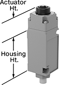 | 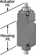 | 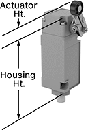 |
Style A | Style B | Style C |
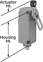 | 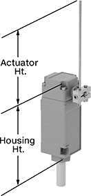 | 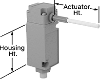 |
Style D | Style E | Style F |
Housing | ||||||||||||||||||||
|---|---|---|---|---|---|---|---|---|---|---|---|---|---|---|---|---|---|---|---|---|
Style | No. of Circuits Controlled | Switch Starting Position | Switch Action | Switch Designation | Switching Current @ Voltage | Max. Voltage | Actuation Torque | Operating Temp. Range, ° F | Actuator Ht. | No. of Wire Leads | Cable Lead Lg., ft. | Lg. | Ht. | Dp. | Housing Material | Enclosure Rating | Each | |||
Plunger Actuator | ||||||||||||||||||||
Wire Lead Connection | ||||||||||||||||||||
| A | 1 | 1 Off or 1 On | Momentary | SPDT | 10 amp @ 240V AC, 1 amp @ 250V DC | 240V AC 250V DC | — | 14 to 221 | 1.5" | 5 | 8 | 1.5" | 3.1" | 1.6" | Zinc | NEMA 3S, NEMA 6P, NEMA 13, IP67, IP69K | 7926K101 | 0000000 | ||
| A | 2 | 2 Off or 2 On | Momentary | DPDT | 10 amp @ 240V AC, 1 amp @ 250V DC | 240V AC 250V DC | — | 14 to 221 | 1.5" | 5 | 8 | 1.5" | 3.1" | 1.6" | Zinc | NEMA 3S, NEMA 6P, NEMA 13, IP67, IP69K | 7926K102 | 000000 | ||
Roller Plunger Actuator | ||||||||||||||||||||
Wire Lead Connection | ||||||||||||||||||||
| B | 2 | 2 Off or 2 On | Momentary | DPDT | 10 amp @ 240V AC, 1 amp @ 250V DC | 240V AC 250V DC | — | 14 to 221 | 1.9" | 5 | 8 | 1.5" | 3.1" | 1.6" | Zinc | NEMA 3S, NEMA 6P, NEMA 13, IP67, IP69K | 7926K103 | 000000 | ||
Roller Lever Actuator | ||||||||||||||||||||
Wire Lead Connection | ||||||||||||||||||||
| C | 1 | 1 Off or 1 On | Momentary | SPDT | 10 amp @ 240V AC, 1 amp @ 250V DC | 240V AC 250V DC | 0.53 in·ozf | 10 to 200 | 1.5" | 5 | 8 | 1.5" | 4.6" | 1.6" | Zinc | NEMA 3S, NEMA 6P, NEMA 13, IP67, IP69K | 7926K151 | 000000 | ||
| C | 2 | 2 Off or 2 On | Momentary | DPDT | 10 amp @ 240V AC, 1 amp @ 250V DC | 240V AC 250V DC | 0.53 in·ozf | 10 to 200 | 1.5" | 5 | 8 | 1.5" | 4.6" | 1.6" | Zinc | NEMA 3S, NEMA 6P, NEMA 13, IP67, IP69K | 7926K152 | 000000 | ||
| D | 1 | 1 Off or 1 On | Momentary | SPDT | 10 amp @ 240V AC, 1 amp @ 250V DC | 240V AC 250V DC | 1.9 in·ozf | 10 to 200 | 1" to 3.75" | 5 | 8 | 1.5" | 4.6" | 1.6" | Zinc | NEMA 3S, NEMA 6P, NEMA 13, IP67, IP69K | 7926K153 | 000000 | ||
| D | 2 | 2 Off or 2 On | Momentary | DPDT | 10 amp @ 240V AC, 1 amp @ 250V DC | 240V AC 250V DC | 1.9 in·ozf | 10 to 200 | 1" to 3.75" | 5 | 8 | 1.5" | 4.6" | 1.6" | Zinc | NEMA 3S, NEMA 6P, NEMA 13, IP67, IP69K | 7926K154 | 000000 | ||
Rod Actuator | ||||||||||||||||||||
Wire Lead Connection | ||||||||||||||||||||
| E | 1 | 1 Off or 1 On | Momentary | SPDT | 10 amp @ 240V AC, 1 amp @ 250V DC | 240V AC 250V DC | 0.92 in·ozf | 10 to 200 | 0" to 5.5" | 5 | 8 | 1.5" | 4.6" | 1.6" | Zinc | NEMA 3S, NEMA 6P, NEMA 13, IP67, IP69K | 7926K155 | 000000 | ||
| E | 2 | 2 Off or 2 On | Momentary | DPDT | 10 amp @ 240V AC, 1 amp @ 250V DC | 240V AC 250V DC | 0.92 in·ozf | 10 to 200 | 0" to 5.5" | 5 | 8 | 1.5" | 4.6" | 1.6" | Zinc | NEMA 3S, NEMA 6P, NEMA 13, IP67, IP69K | 7926K156 | 000000 | ||
Wobble Stick Actuator | ||||||||||||||||||||
Wire Lead Connection | ||||||||||||||||||||
| F | 1 | 1 Off or 1 On | Momentary | SPDT | 10 amp @ 240V AC, 1 amp @ 250V DC | 240V AC 250V DC | Not Rated | 10 to 200 | 0" to 2.25" | 5 | 8 | 1.5" | 4.6" | 1.6" | Zinc | NEMA 3S, NEMA 6P, NEMA 13, IP67, IP69K | 7926K157 | 000000 | ||
| F | 2 | 2 Off or 2 On | Momentary | DPDT | 10 amp @ 240V AC, 1 amp @ 250V DC | 240V AC 250V DC | Not Rated | 10 to 200 | 0" to 5" | 5 | 8 | 1.5" | 4.6" | 1.6" | Zinc | NEMA 3S, NEMA 6P, NEMA 13, IP67, IP69K | 7926K158 | 000000 | ||
Outdoor Durable Disconnect Switches
Maintained Switch
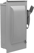 |
Powder-Coated Steel Housing—The enclosure is steel, so it withstands tougher conditions than plastic enclosures.
Fuse Holder—Use switches with a fuse holder where overload protection is needed. When the current exceeds the rating of the fuse, it blows. This interrupts the circuit and prevents overheating, damage, and fire. When used with UL Class RK1, RK5, or T fuses, they require rejection-style fuse clips. Note: Horsepower ratings are based on time-delay fuses installed.
Lockout—They have a lockout to secure in the off position using a padlock (not included).
Safety Interlock—Switches with safety interlock keep the door closed when the switch is on and prevent the switch from turning on when the door is open.
NEMA 3R Enclosure Rating—A raintight NEMA 3R rated enclosure protects these switches from falling liquids and light splashing.
Switches | Rejection-Style Fuse Clips for RK1 and RK5 Fuse Class | ||||||||||||||||
|---|---|---|---|---|---|---|---|---|---|---|---|---|---|---|---|---|---|
Switching | |||||||||||||||||
Current, amp | Voltage | Switch Designation | Electrical Phase (hp) | For No. of Wires | For Fuse UL Class | Ht. | Wd. | For Max. Padlock Shackle Dia. | Wire Connection | Enclosure Rating | Certification | Each | Each | ||||
Gray Powder-Coated Steel Housing with Red Actuator | |||||||||||||||||
2 Circuits Controlled with Lockout, Safety Interlock, and Fuse Holder | |||||||||||||||||
| 100 | 240V AC/250V DC | DPST | Single (15 hp @ 240V AC) | 3 | RK1, RK5, K5, T, H | 17 1/2" | 11 3/16" | 5/16" | Tab | NEMA 3R | UL Listed | 7524K26 | 0000000 | 7524K413 | 000000 | ||
2 Circuits Controlled with Lockout and Fuse Holder | |||||||||||||||||
| 30 | 240V AC/250V DC | DPST | Single (3 hp @ 240V AC) | 3 | RK1, RK5, K5, H | 8 9/16" | 5 7/16" | 5/16" | Tab | NEMA 3R | UL Listed | 7524K24 | 000000 | 7524K411 | 000000 | ||
| 60 | 240V AC/250V DC | DPST | Single (10 hp @ 240V AC) | 3 | RK1, RK5, K5, H | 10 1/16" | 6 7/16" | 5/16" | Tab | NEMA 3R | UL Listed | 7524K25 | 000000 | 7524K412 | 00000 | ||
3 Circuits Controlled with Lockout and Safety Interlock | |||||||||||||||||
| 100 | 240V AC/250V DC | 3PST | Three (30 hp @ 240V AC) | 3 | — | 17 1/2" | 11 3/16" | 5/16" | Tab | NEMA 3R | UL Listed | 7524K36 | 000000 | ——— | 0 | ||
3 Circuits Controlled with Lockout, Safety Interlock, and Fuse Holder | |||||||||||||||||
| 100 | 240V AC/250V DC | 3PST | Single (15 hp @ 240V AC) Three (30 hp @ 240V AC) | 4 | RK1, RK5, K5, T, H | 23 1/8" | 11 3/4" | 5/16" | Tab | NEMA 3R | UL Listed | 7524K16 | 000000 | 7524K413 | 00000 | ||
3 Circuits Controlled with Lockout and Fuse Holder | |||||||||||||||||
| 30 | 240V AC/250V DC | 3PST | Single (3 hp @ 240V AC) Three (7 1/2 hp @ 240V AC) | 4 | RK1, RK5, K5, H | 8 9/16" | 5 7/16" | 5/16" | Tab | NEMA 3R | UL Listed | 7524K14 | 000000 | 7524K411 | 000000 | ||
| 60 | 240V AC/250V DC | 3PST | Single (10 hp @ 240V AC) Three (15 hp @ 240V AC) | 4 | RK1, RK5, K5, H | 10 1/16" | 6 7/16" | 5/16" | Tab | NEMA 3R | UL Listed | 7524K15 | 000000 | 7524K412 | 00000 | ||
3 Circuits Controlled with Lockout | |||||||||||||||||
| 30 | 240V AC/250V DC | 3PST | Three (7 1/2 hp @ 240V AC) | 3 | — | 6 3/8" | 4 9/16" | 5/16" | Tab | NEMA 3R | UL Listed | 7524K34 | 000000 | ——— | 0 | ||
| 60 | 240V AC/250V DC | 3PST | Three (15 hp @ 240V AC) | 3 | — | 8 9/16" | 5 7/16" | 5/16" | Tab | NEMA 3R | UL Listed | 7524K35 | 000000 | ——— | 0 | ||
Rotary Limit Switches
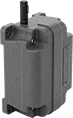 |
Start or stop equipment after a set number of rotations to avoid over-rotation. For example, if attached to a crane spool, these switches will stop winding or unwinding cable after a certain number of rotations, preventing damage to equipment. Use their shaft to attach them to rotational equipment. They open and close circuits as fast as snap-acting switches.
Gear Speed Ratio—Gear speed ratio determines when these switches actuate. A gear speed ratio of 5:1 means they actuate after 5 rotations.
Housing | Shaft | ||||||||||||||||||||
|---|---|---|---|---|---|---|---|---|---|---|---|---|---|---|---|---|---|---|---|---|---|
Gear Speed Ratio | No. of Circuits Controlled | Switch Starting Position | Switch Action | Switch Designation | Switching Current @ Voltage | Max. Voltage | Operating Temp. Range, ° F | No. of Terminals | Lg. | Ht. | Dp. | Housing Material | Type | Lg. | Dia. | Conduit Trade Size | Enclosure Rating | Each | |||
Rotary Actuator | |||||||||||||||||||||
Screw-Terminal Wire Connection | |||||||||||||||||||||
| 5:1 | 2 | 1 Off or 1 On | Momentary | SPDT | 15 amp @ 250V AC, 0.25 amp @ 250V DC | 480V AC 250V DC | -40 to 180 | 3 | 6" | 2.8" | 4.5" | Aluminum | Keyed | 1 1/2" | 1/2" | 1/2 | NEMA 4 | 7821N11 | 000000000 | ||
| 20:1 | 2 | 1 Off or 1 On | Momentary | SPDT | 15 amp @ 250V AC, 0.25 amp @ 250V DC | 480V AC 250V DC | -40 to 180 | 3 | 6" | 2.8" | 4.5" | Aluminum | Keyed | 1 1/2" | 1/2" | 1/2 | NEMA 4 | 7821N12 | 00000000 | ||
| 40:1 | 2 | 1 Off or 1 On | Momentary | SPDT | 15 amp @ 250V AC, 0.25 amp @ 250V DC | 480V AC 250V DC | -40 to 180 | 3 | 6" | 2.8" | 4.5" | Aluminum | Keyed | 1 1/2" | 1/2" | 1/2 | NEMA 4 | 7821N13 | 00000000 | ||
| 100:1 | 2 | 1 Off or 1 On | Momentary | SPDT | 15 amp @ 250V AC, 0.25 amp @ 250V DC | 480V AC 250V DC | -40 to 180 | 3 | 6" | 2.8" | 4.5" | Aluminum | Keyed | 1 1/2" | 1/2" | 1/2 | NEMA 4 | 7821N14 | 00000000 | ||
Foot Switches
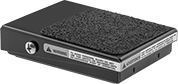 | 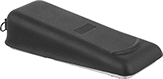 |
Back Pivot with 1 Pedal | Center Pivot with 1 Pedal |
Keep your hands free for other tasks by triggering switches with your foot.
2 Speeds—Two-speed switches have staged contacts. For slow speed, push the pedal halfway to close the first contact; for high speed, push it all the way to close the second contact.
Back—Back-pivot switches actuate with a tap of the toe.
Center—Center-pivot switches let you control two circuits with a single foot—one with your toe and one with your heel. Also known as rocker switches, they can be pressed either forward or backward, meaning you actuate one circuit at a time.
No. of Circuits Controlled | Switch Starting Position | Switch Action | Switch Designation | Switching Current @ Voltage | Housing Material | Wire Connection | No. of Terminals | Each | |||
|---|---|---|---|---|---|---|---|---|---|---|---|
1 Speed | |||||||||||
Center Pivot with 1 Pedal | |||||||||||
| 2 | 1 Off or 1 On | Momentary | SPDT | 15 amp @ 125V AC, 250V AC, 0.5 amp @ 125V DC, 0.25 amp @ 250V DC | Aluminum | Tab | 6 | 5767N13 | 0000000 | ||
2 Speeds | |||||||||||
Back Pivot with 1 Pedal | |||||||||||
| 1 | 1 Off or 1 On | Momentary | SPDT | 10 amp @ 125V AC, 250V AC, 0.5 amp @ 125V DC, 0.25 amp @ 250V DC | Aluminum | Tab | 6 | 5767N12 | 000000 | ||
Hazardous Location Cable-Pull-Actuator Emergency Stop Switches
 |
Safe to use near ignitable gases and dust, the housing on these switches seals in anything that could ignite flammable material. All are UL listed and CSA certified for use in hazardous locations. Yank the cable anywhere along your line to quickly cut power in emergencies. They have positive-force, snap-open contacts that open a circuit when actuated, even if a spring fails or the contacts stick. The contacts will remain open until you tension the cable and reset the switch. Use the tension indicator to visually confirm that they’re reset correctly.
Mounting | ||||||||||||||||
|---|---|---|---|---|---|---|---|---|---|---|---|---|---|---|---|---|
For Max. Cable Lg., ft. | No. of Circuits Controlled | Switch Starting Position | No. of Terminals | Switch Designation | Switching Current @ Voltage | Max. Voltage | Actuation Force, lbf | Conduit Trade Size | Fasteners Included | Hole Dia. (No. of Holes) | Hole Thread Size (No. of Holes) | Features | Each | |||
Screw-Terminal Wire Connection | ||||||||||||||||
1 Direction (NEMA 4; NEMA 7; NEMA 9; NEMA 13; NEC Class I Divisions 1, 2 Groups B, C, D; NEC Class II Divisions 1, 2 Groups E, F, G) | ||||||||||||||||
| 200 | 1 | 1 Off or 1 On | 3 | SPDT | 10 amp @ 600V AC 10 amp @ 250V DC | 600V AC 250V DC | 25 | 1/2 | No | 1/4" (2) | 5/16"-18 (2) | Tension Indicator | 7543N11 | 000000000 | ||
| 200 | 2 | 2 On | 4 | DPST-NC | 10 amp @ 600V AC 10 amp @ 250V DC | 600V AC 250V DC | 25 | 1/2 | No | 1/4" (2) | 5/16"-18 (2) | Tension Indicator | 7543N12 | 00000000 | ||
Frame-Mounted Safety Switches
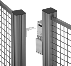 |
Key Shown Actuating from the Side |
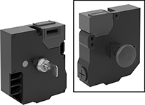 |
Style J |
Also known as interlock switches, these ensure the safety of personnel by automatically shutting off power to machinery when an access door opens. Mount the switch to the door frame and mount a key to the door so that the key is inserted into the switch when the door is closed. When the door opens, the key is removed from the switch and the machine shuts down. They’re often used with machine guards for large robots.
Style J—Style J switches have extra safety controls to prevent you from getting trapped next to running machinery. They actuate with the turn of a portable key. Bring the key when you enter an enclosure to ensure machinery won’t start while you’re inside, even if the door closes behind you. As an added fail-safe, a rear release button lets you cut power from inside of enclosures if needed. These switches have light-up indicators that show when they're properly installed and whether they're actuated.
IP67 Enclosure Rating—IP67 rated switches protect against temporary submersion.
Key Included—All switches require an actuator key, but not all include one—check whether you need to pick out a separate actuator key. For some switch styles, you can also select the mounting orientation of the key.
Housing | Conduit | |||||||||||||||||
|---|---|---|---|---|---|---|---|---|---|---|---|---|---|---|---|---|---|---|
Style | No. of Circuits Controlled | Switch Starting Position | Switch Action | No. of Terminals | Switch Designation | Switching Current @ Voltage | Max. Voltage | Ht. | Wd. | Dp. | Thread Size | Thread Type | Key Included | Enclosure Rating | Each | |||
Screw-Terminal Wire Connection with Rear Release Button, Portable Key, and LED Status Indicator | ||||||||||||||||||
| J | 6 | 2 Off and 4 On | Maintained | 12 | 6PST-2NO/4NC | 3 amp @ 240V AC, 2.5 amp @ 250V DC | 240V AC 250V DC | 5.2" | 4.6" | 2.2" | M20 | Metric | Yes | IP67 | 65665K101 | 0000000 | ||
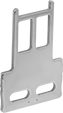

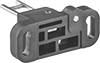
Safety Relays with Diagnostic Capabilities
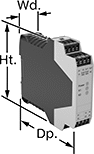 | 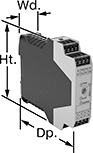 |
Relay | Relay with Time Delay |
Control and diagnose issues with safety-critical circuits. These relays have a microprocessor that monitors safety components, such as emergency stops and light curtains, and sends a signal to stop the operation if a failure is detected and restart when the issue is resolved. They also help with diagnostic tasks because of their feedback circuit, which allows basic relays to communicate their status back to the safety relay. These relays have a duplicate set of input and output signals, so they’ll still stop the controlled device if one of the inputs fails.
IP20 rated, they have recessed terminals which prevent fingers and other objects from touching live circuits. These relays have been tested to multiple safety standards and can help achieve PL, SIL, or CAT system ratings. They also meet ISO and IEC standards for machine safety.
Mount them to 35 mm DIN rail (also known as DIN 3 Rail) for fast installation.
Time Delay—Relays with delayed safety outputs are often used where power must be maintained after an input signal is received. For example, after a stop button for a machine is pressed, the guard door will stay locked until the machine cycle is finished.
No. of Terminals | Input Voltage | Switching Current @ Voltage | Max. Switching Voltage | Ht. | Wd. | Dp. | For Use With | Mounting Location | Max. System Safety Rating | Features | Each | |||
|---|---|---|---|---|---|---|---|---|---|---|---|---|---|---|
2 Circuits Controlled | ||||||||||||||
2 Safety Outputs with 2 Off and 2 Delayed Safety Outputs with 2 Off | ||||||||||||||
| 16 | 24V DC | 3 amp @ 240V AC 3 amp @ 24V DC | 250V AC, 250V DC | 3.9" | 0.9" | 4.5" | Emergency Stops, Safety Light Curtains | DIN Rail | PLe, SIL 3 | Time Delay | 6322N15 | 0000000 | ||
2 Safety Outputs with 2 Off and 1 Signal Output with 2 On | ||||||||||||||
| 16 | 24V AC, 24V DC | 5 amp @ 240V AC 5 amp @ 24V DC | 250V AC, 250V DC | 3.9" | 0.9" | 4.5" | Two-Hand Switches | DIN Rail | PLe, SIL 3 | — | 6322N16 | 000000 | ||
3 Safety Outputs with 2 Off and 1 Signal Output with 2 On | ||||||||||||||
| 16 | 240V AC | 3 amp @ 240V AC 2.5 amp @ 24V DC | 250V AC, 250V DC | 3.9" | 1.8" | 4.5" | Emergency Stops | DIN Rail | PLe, SIL 3 | — | 6322N13 | 000000 | ||
| 24 | 24V AC, 48V AC, 120V AC, 240V AC, 24V DC, 48V DC, 60V DC, 120V DC, 240V DC | 5 amp @ 240V AC 5 amp @ 24V DC | 250V AC, 250V DC | 4.42" | 0.9" | 4.5" | Emergency Stops | DIN Rail | PLe, SIL 3 | — | 6322N14 | 00000000 | ||
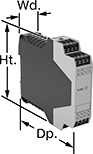 | 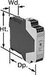 |
Auxiliary Contact Block | Auxiliary Contact Block with Time Delay |
No. of Terminals | Input Voltage, V DC | Switching Current @ Voltage | Max. Switching Voltage | Ht. | Wd. | Dp. | Features | Each | |||
|---|---|---|---|---|---|---|---|---|---|---|---|
5 Safety Outputs | |||||||||||
| 16 | 24 | 3 amp @ 240V AC 2.5 amp @ 24V DC | 250V AC, 250V DC | 3.9" | 0.9" | 4.5" | — | 6322N22 | 0000000 | ||
4 Delayed Safety Outputs | |||||||||||
| 16 | 24 | 3 amp @ 240V AC 3 amp @ 24V DC | 250V AC, 250V DC | 3.9" | 0.9" | 4.5" | Time Delay | 6322N18 | 000000 | ||
Current-Monitoring Relays
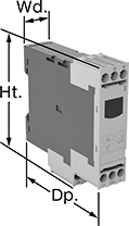 | 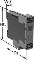 |
Screw Terminals with IO-Link, Keypad Adjustment | Spring-Clamp Terminals with IO-Link, Keypad Adjustment |
Protect electrical equipment from overcurrent and undercurrent damage—these relays continuously monitor current flow. When current is outside a set range, they trip and cut power to prevent overheating, fire hazards, and stalling. Rated IP20, these relays have recessed terminals that keep fingers and other objects from touching live circuits. Mount them on a 35 mm DIN rail (also known as DIN 3 rail) for fast installation.
Spring-Clamp-Terminal Wire Connection—Relays with spring-clamp terminals connect and disconnect to wire without screws. Because there’s no screw, these connections are less likely to loosen over time, even in high-vibration environments.
IO-Link Communication Protocol—Relays with IO-Link can be programmed, monitored, and reset remotely by connecting them to a programmable logic controller (PLC), human-machine interface (HMI), or computer. If you want to program them locally, they have a keypad.
No. of Terminals | Input Voltage, V DC | Trip Current, amp | Trip Time, sec. | Reset Type | Switching Current @ Voltage | Max. Switching Voltage | Adjustment Mechanism | Ht. | Wd. | Dp. | Digital Display Type | Each | |||
|---|---|---|---|---|---|---|---|---|---|---|---|---|---|---|---|
Screw Terminals with IO-Link | |||||||||||||||
1 Circuit Controlled with 1 Off or 1 On—SPDT | |||||||||||||||
| 9 | 24 | 0.05 to 10 | 0 to 999 | Automatic | 3 amp @ 240V AC 1 amp @ 24V DC | 400V AC 250V DC | External Controller, Keypad | 3.6" | 0.9" | 3.4" | LCD | 8123N11 | 0000000 | ||
Spring-Clamp Terminals with IO-Link | |||||||||||||||
1 Circuit Controlled with 1 Off or 1 On—SPDT | |||||||||||||||
| 9 | 24 | 0.05 to 10 | 0 to 999 | Automatic | 3 amp @ 240V AC 1 amp @ 24V DC | 400V AC 250V DC | External Controller, Keypad | 3.8" | 0.9" | 3.4" | LCD | 8123N12 | 000000 | ||
Multifunction Monitoring Relays
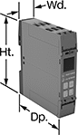 |
Monitor phase, voltage, and frequency at the same time to protect motors, generators, and other three-phase circuits from burning out or overheating. They'll switch the circuit off if they detect voltage or frequencies outside of the set range or phase loss, imbalance, or reversal. Rated IP20, they have recessed terminals that keep fingers and other objects from touching live circuits. Mount them on a 35 mm DIN rail (also known as DIN 3 rail) for fast installation.
These relays use IO-Link, so they can be programmed, monitored, and reset remotely by connecting them to a programmable logic controller (PLC), human-machine interface (HMI), or computer. If you want to program them locally, they have a keypad.
Spring-Clamp-Terminal Wire Connection—Relays with spring-clamp terminals connect and disconnect to wire without screws. Because there’s no screw, these connections are less likely to loosen over time, even in high-vibration environments.
No. of Terminals | Input Voltage, V DC | Trip Voltage, V AC | Input Freq., Hz | Trip Freq., Hz | Trip Time, sec. | Reset Type | Switching Current @ Voltage | Max. Switching Voltage | Adjustment Mechanism | Ht. | Wd. | Dp. | Each | |||
|---|---|---|---|---|---|---|---|---|---|---|---|---|---|---|---|---|
1 Circuit Controlled with 1 Off or 1 On—SPDT | ||||||||||||||||
Screw Terminals with IO-Link | ||||||||||||||||
| 12 | 24 | 90 to 760 | 50, 60 | 15 to 70 | 0.1 to 30 | Automatic | 3 amp @ 240V AC 1 amp @ 24V DC | 400V AC 250V DC | External Controller, Keypad | 3.9" | 0.9" | 3.6" | 8449N12 | 0000000 | ||
Spring-Clamp Terminals with IO-Link | ||||||||||||||||
| 12 | 24 | 90 to 760 | 50, 60 | 15 to 70 | 0.1 to 30 | Automatic | 3 amp @ 240V AC 1 amp @ 24V DC | 400V AC 250V DC | External Controller, Keypad | 3.9" | 0.9" | 3.6" | 8449N11 | 000000 | ||
Voltage-Monitoring Relays
Monitoring Relays with IO-Link
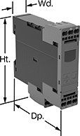 |
Relays with IO-Link can be programmed, monitored and reset remotely by connecting them to a programmable logic controller (PLC), human-machine interface (HMI), or computer. If you want to program them locally, they have a keypad.
With Spring-Clamp Terminals—Relays with spring-clamp terminals connect and disconnect to wire without screws. Because there’s no screw, these connections are less likely to loosen over time, even in high-vibration environments.
No. of Terminals | Input Voltage, V DC | Trip Voltage | Trip Time, sec. | Reset Type | Switching Current @ Voltage | Max. Switching Voltage | Adjustment Mechanism | Ht. | Wd. | Dp. | Digital Display Type | Features | Each | |||
|---|---|---|---|---|---|---|---|---|---|---|---|---|---|---|---|---|
1 Circuit Controlled with 1 Off or 1 On—SPDT | ||||||||||||||||
With Screw Terminals | ||||||||||||||||
| 9 | 24 | 10V AC to 600V AC, 10V DC to 600V DC | 0 to 999 | Automatic | 3 amp @ 240V AC 1 amp @ 24V DC | 400V AC 250V DC | External Controller, Keypad | 3.6" | 0.9" | 3.6" | LCD | Remote Reset | 8446N105 | 0000000 | ||
With Spring-Clamp Terminals | ||||||||||||||||
| 9 | 24 | 10V AC to 600V AC, 10V DC to 600V DC | 0 to 999 | Automatic | 3 amp @ 240V AC 1 amp @ 24V DC | 400V AC 250V DC | External Controller, Keypad | 3.8" | 0.9" | 3.6" | LCD | Remote Reset | 8446N106 | 000000 | ||
Ground-Fault Monitoring Relays
 |  |
Screw Terminals with IO-Link | Spring-Clamp Terminals with IO-Link |
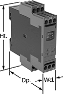
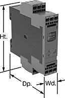
Detect and mitigate ground faults to prevent harm to equipment, circuits, and people. These relays monitor the differential between incoming and outgoing current, also known as residual current. When the balance is off, they trip and cut power to the circuit. These relays are highly sensitive, so you can trust them to de-energize faulty circuits before a minor issue becomes a major one. Rated IP20, they have recessed terminals that keep fingers and other objects from touching live circuits. Mount them on 35 mm DIN rail (also known as DIN 3 rail) for fast installation.
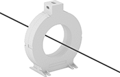
These relays require a current-indicating ring (sold separately) to operate. Choose a ring that is large enough for your lines to pass through. Feed the lines of the circuit through the center of the ring and connect the indicating ring output to the relay.
Spring-Clamp-Terminal Wire Connection—Relays with spring-clamp terminals connect and disconnect to wire without screws. Because they don’t have screws, there’s less of a risk that they will loosen over time, even when they’re under vibration.
IO-Link Communication Protocol—Relays with IO-Link can be programmed, monitored, and reset remotely by connecting them to a programmable logic controller (PLC), human-machine interface (HMI), or computer. If you want to program them locally, they have a keypad.
No. of Terminals | Input Voltage, V DC | Trip Current, amp | Trip Time, sec. | Switching Current @ Voltage | Max. Switching Voltage | Adjustment Mechanism | Ht. | Wd. | Dp. | Features | Each | |||
|---|---|---|---|---|---|---|---|---|---|---|---|---|---|---|
Screw Terminals with IO-Link | ||||||||||||||
2 Circuits Controlled with 2 Off or 2 On—DPDT | ||||||||||||||
| 12 | 24 | 0.03 to 40 | 0 to 999 | 3 amp @ 240V AC 1 amp @ 24V DC | 400V AC 250V DC | External Controller, Keypad | 4" | 0.9" | 3.6" | Remote Reset | 8121N109 | 0000000 | ||
Spring-Clamp Terminals with IO-Link | ||||||||||||||
2 Circuits Controlled with 2 Off or 2 On—DPDT | ||||||||||||||
| 12 | 24 | 0.03 to 40 | 0 to 999 | 3 amp @ 240V AC 1 amp @ 24V DC | 400V AC 250V DC | External Controller, Keypad | 4.1" | 0.9" | 3.6" | Remote Reset | 8121N111 | 000000 | ||