


Filter by
System of Measurement
Switching Voltage
Actuator Style

Housing Material
Switch Starting Position
Electrical Connection Type
Actuator Height
Switch Action
Wire Connection

Certification
Conduit Thread Type
Mounting Location
DFARS Specialty Metals
Export Control Classification Number (ECCN)
Limit Switches
 |  |  |
Style A | Style B | Style D |
 |  |  |
Style E | Style F | Style H |
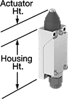
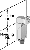
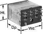
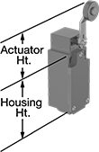
When a moving object contacts the actuator on these switches, they open or close a circuit. They have the rapid-closing action of a snap-acting switch, but with a larger actuator. This makes them a good choice for use with large objects—for instance, a box on a conveyor runs into the switch, stopping the conveyor.
Plunger Actuator—Switches with a plunger actuator require a push to actuate, similar to a button.
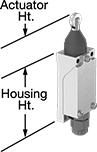
Roller Plunger Actuator—Switches with a roller plunger actuator have a roller that moves when an object pushes the actuator. This reduces friction during actuation to limit wear and tear on your switch.
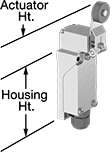
Roller Lever Actuator—Switches with a roller lever actuator use a lever with a roller at the end to activate. This allows parts to glide across the actuation surface with minimal friction, limiting wear and tear on your switch.
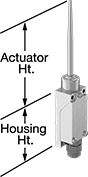
Rod Actuator—Switches with a rod actuator use a rod extending out of the body to actuate, so they’ll activate even if an object is far away.
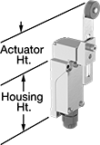
Wobble Stick Actuator—Switches with a wobble stick actuator have an arm that rotates 360°, so you don’t need to align it in a specific direction. Since the actuator is flexible, it won’t snap if pushed backward. That makes these switches a great choice for systems that get jammed often.
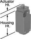
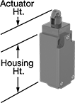
Styles E and F—Styles E and F let you adjust the actuator’s height to align it with your target.
IP67 Enclosure Rating—Switches rated IP67 are protected against dust and temporary submersion.
Housing | ||||||||||||||||||||
|---|---|---|---|---|---|---|---|---|---|---|---|---|---|---|---|---|---|---|---|---|
Style | No. of Circuits Controlled | Switch Starting Position | Switch Action | Switch Designation | Switching Current @ Voltage | Max. Voltage | Actuation Torque, in·ozf | Operating Temp. Range, ° F | Actuator Ht. | No. of Terminals | Lg. | Ht. | Dp. | Housing Material | Conduit Trade Size | Enclosure Rating | Each | |||
Plunger Actuator | ||||||||||||||||||||
Screw-Terminal Wire Connection | ||||||||||||||||||||
| A | 1 | 1 Off or 1 On | Momentary | SPDT | 10 amp @ 300V AC, 6 amp @ 24V DC | 300V AC 250V DC | — | 14 to 176 | 1.1" | 4 | 1.6" | 2.7" | 1.6" | Aluminum | 1/2 | IP67 | 7076K27 | 000000 | ||
Roller Plunger Actuator | ||||||||||||||||||||
Screw-Terminal Wire Connection | ||||||||||||||||||||
| B | 1 | 1 Off or 1 On | Momentary | SPDT | 10 amp @ 300V AC, 6 amp @ 24V DC | 300V AC 250V DC | — | 14 to 176 | 1.6" | 4 | 1.6" | 2.7" | 1.6" | Aluminum | 1/2 | IP67 | 7076K26 | 000000 | ||
Roller Lever Actuator | ||||||||||||||||||||
Screw-Terminal Wire Connection | ||||||||||||||||||||
| D | 1 | 1 Off or 1 On | Momentary | SPDT | 10 amp @ 300V AC, 6 amp @ 24V DC | 300V AC 250V DC | 48 | 14 to 176 | 2.2" | 4 | 1.6" | 2.7" | 1.6" | Aluminum | 1/2 | IP67 | 7076K14 | 000000 | ||
| E | 1 | 1 Off or 1 On | Momentary | SPDT | 10 amp @ 300V AC, 6 amp @ 24V DC | 300V AC 250V DC | 48 | 14 to 176 | 1.7" to 4.2" | 4 | 1.6" | 2.7" | 1.6" | Aluminum | 1/2 | IP67 | 7076K18 | 000000 | ||
Rod Actuator | ||||||||||||||||||||
Screw-Terminal Wire Connection | ||||||||||||||||||||
| F | 1 | 1 Off or 1 On | Momentary | SPDT | 10 amp @ 300V AC, 6 amp @ 24V DC | 300V AC 250V DC | 50.6 | 14 to 176 | 1.4" to 5.9" | 4 | 1.6" | 2.7" | 1.6" | Aluminum | 1/2 | IP67 | 7076K24 | 000000 | ||
Wobble Stick Actuator | ||||||||||||||||||||
Screw-Terminal Wire Connection | ||||||||||||||||||||
| H | 1 | 1 Off or 1 On | Momentary | SPDT | 10 amp @ 300V AC, 6 amp @ 24V DC | 300V AC 250V DC | — | 14 to 176 | 5.3" | 4 | 1.6" | 2.7" | 1.6" | Aluminum | 1/2 | IP67 | 7076K25 | 000000 | ||
Washdown 3/4" Panel-Mount Key Switches
 |
Screw-Terminal Wire Connection |
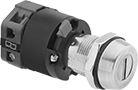
Rated NEMA 4 or IP66, these switches are protected from washdowns. They require a key to turn circuits on or off, limiting access to sensitive equipment. All fit into a standard panel cutout.
Keyed Alike—Keyed alike switches all open with the same key.
Keyed Differently—Keyed differently switches each open with a unique key.
Key Switches | Replacement Keys | ||||||||||||||||
|---|---|---|---|---|---|---|---|---|---|---|---|---|---|---|---|---|---|
No. of Circuits Controlled | Switch Starting Position | Switch Action | No. of Terminals | Switch Designation | Switching Current @ Voltage | Max. Voltage | Dia. | Dp. Behind Panel | No. of Keys Included | Key Removal Position | Enclosure Rating | Each | Each | ||||
2 Positions with Metal Actuator Base | |||||||||||||||||
Keyed Alike with Screw-Terminal Wire Connection | |||||||||||||||||
| 2 | 1 Off and 1 On | Maintained | 4 | DPST-1NO/1NC | 10 amp @ 300V AC/24V DC | 300V AC 24V DC | 7/8" | 1 7/8" | 2 | Center, Right | NEMA 4, IP66 | 7182K13 | 000000 | 7182K2 | 00000 | ||
Keyed Differently with Screw-Terminal Wire Connection | |||||||||||||||||
| 2 | 1 Off and 1 On | Maintained | 4 | DPST-1NO/1NC | 10 amp @ 300V AC/24V DC | 300V AC 24V DC | 7/8" | 1 7/8" | 2 | Center, Right | NEMA 4, IP66 | 7182K14 | 00000 | ——— | 0 | ||
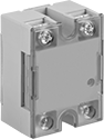
Compact Spade-Terminal Relays
 |  | 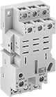 |
11-Terminal Relay | 14-Terminal Relay | 11-Terminal Relay Socket |
 | 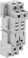 | |
14-Terminal Relay Socket | 8-Terminal Relay Socket |
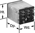
Fit these relays where standard spade-terminal relays are too big. You can connect them three ways. Plug them into a socket (sold separately), connect them with quick-disconnect terminals, or solder wires directly to the terminals. An LED indicator shows you the status of the relay, so you know it’s connected and wired correctly.
2 Circuits Controlled, 3 Circuits Controlled, and 4 Circuits Controlled—Relays that control 2 or more circuits have a lockable test button, so you can test their function. When you press the button, the relay switches contacts. Use this button when checking a relay for proper function before installing it, or when investigating issues with wired relays.
Sockets with Screw Terminals—Relay sockets mount directly on 35 mm DIN rail (also known as DIN 3 rail) for fast installation. You can also mount them to a flat surface using screws.
Relays | Sockets with Screw Terminals | |||||||||||||||
|---|---|---|---|---|---|---|---|---|---|---|---|---|---|---|---|---|
No. of Terminals | Input Voltage | Control Current, mA | Switching Current @ Voltage | Max. Switching Voltage, V AC | hp @ Switching Voltage | Ht. | Wd. | Dp. | Quick-Disconnect Tab Wd. | Features | Each | Each | ||||
2 Circuits Controlled with 2 Off or 2 On—DPDT | ||||||||||||||||
Relay-Socket Mount | ||||||||||||||||
| 8 | 24V AC | 50 | 10 amp @ 120V AC/24V DC | 300 | 1/2 hp @ 120V AC 1 hp @ 277V AC | 1.1" | 0.8" | 1.6" | 0.11" | LED Indicator, Lockable Test Button, Mechanical Flag Indicator | 69585K111 | 000000 | 69585K6 | 00000 | ||
| 8 | 24V AC | 50 | 15 amp @ 120V AC 12 amp @ 24V DC | 300 | 1/2 hp @ 120V AC 1 hp @ 277V AC | 1.1" | 0.9" | 1.6" | 0.187" | LED Indicator, Lockable Test Button, Mechanical Flag Indicator | 69585K57 | 00000 | 69585K1 | 0000 | ||
| 8 | 120V AC | 10 | 10 amp @ 120V AC/24V DC | 300 | 1/2 hp @ 120V AC 1 hp @ 277V AC | 1.1" | 0.8" | 1.6" | 0.11" | LED Indicator, Lockable Test Button, Mechanical Flag Indicator | 69585K112 | 00000 | 69585K6 | 0000 | ||
| 8 | 120V AC | 10 | 15 amp @ 120V AC 12 amp @ 24V DC | 300 | 1/2 hp @ 120V AC 1 hp @ 277V AC | 1.1" | 0.9" | 1.6" | 0.187" | LED Indicator, Lockable Test Button, Mechanical Flag Indicator | 69585K58 | 00000 | 69585K1 | 0000 | ||
| 8 | 240V AC | 5 | 10 amp @ 120V AC/24V DC | 300 | 1/2 hp @ 120V AC 1 hp @ 277V AC | 1.1" | 0.8" | 1.6" | 0.11" | LED Indicator, Lockable Test Button, Mechanical Flag Indicator | 69585K113 | 00000 | 69585K6 | 0000 | ||
| 8 | 240V AC | 5 | 15 amp @ 120V AC 12 amp @ 24V DC | 300 | 1/2 hp @ 120V AC 1 hp @ 277V AC | 1.1" | 0.9" | 1.6" | 0.187" | LED Indicator, Lockable Test Button, Mechanical Flag Indicator | 69585K59 | 00000 | 69585K1 | 0000 | ||
| 8 | 12V DC | 75 | 10 amp @ 120V AC/24V DC | 300 | — | 1.1" | 0.9" | 1.6" | 0.11" | LED Indicator, Lockable Test Button, Mechanical Flag Indicator | 69585K116 | 0000 | 69585K611 | 0000 | ||
| 8 | 12V DC | 75 | 15 amp @ 120V AC 12 amp @ 24V DC | 300 | 1/2 hp @ 120V AC 1 hp @ 277V AC | 1.1" | 0.9" | 1.6" | 0.187" | LED Indicator, Lockable Test Button, Mechanical Flag Indicator | 69585K66 | 00000 | 69585K1 | 0000 | ||
| 8 | 24V DC | 38 | 15 amp @ 120V AC 12 amp @ 24V DC | 300 | 1/2 hp @ 120V AC 1 hp @ 277V AC | 1.1" | 0.9" | 1.6" | 0.187" | LED Indicator, Lockable Test Button, Mechanical Flag Indicator | 69585K67 | 00000 | 69585K1 | 0000 | ||
| 8 | 24V DC | 46 | 10 amp @ 120V AC/24V DC | 300 | 1/2 hp @ 120V AC 1 hp @ 277V AC | 1.1" | 0.8" | 1.6" | 0.11" | LED Indicator, Lockable Test Button, Mechanical Flag Indicator | 69585K115 | 00000 | 69585K6 | 0000 | ||
3 Circuits Controlled with 3 Off or 3 On—3PDT | ||||||||||||||||
Relay-Socket Mount | ||||||||||||||||
| 11 | 24V AC | 63 | 15 amp @ 120V AC 12 amp @ 24V DC | 300 | 1/2 hp @ 120V AC 1 hp @ 277V AC | 1.1" | 1.2" | 1.6" | 0.187" | LED Indicator, Lockable Test Button, Mechanical Flag Indicator | 69585K68 | 00000 | 69585K2 | 00000 | ||
| 11 | 120V AC | 13 | 15 amp @ 120V AC 12 amp @ 24V DC | 300 | 1/2 hp @ 120V AC 1 hp @ 277V AC | 1.1" | 1.2" | 1.6" | 0.187" | LED Indicator, Lockable Test Button, Mechanical Flag Indicator | 69585K69 | 00000 | 69585K2 | 00000 | ||
| 11 | 240V AC | 6 | 15 amp @ 120V AC 12 amp @ 24V DC | 300 | 1/2 hp @ 120V AC 1 hp @ 277V AC | 1.1" | 1.2" | 1.6" | 0.187" | LED Indicator, Lockable Test Button, Mechanical Flag Indicator | 69585K71 | 00000 | 69585K2 | 00000 | ||
| 11 | 12V DC | 117 | 15 amp @ 120V AC 12 amp @ 24V DC | 300 | 1/2 hp @ 120V AC 1 hp @ 277V AC | 1.1" | 1.2" | 1.6" | 0.187" | LED Indicator, Lockable Test Button, Mechanical Flag Indicator | 69585K72 | 00000 | 69585K2 | 00000 | ||
| 11 | 24V DC | 58 | 15 amp @ 120V AC 12 amp @ 24V DC | 300 | 1/2 hp @ 120V AC 1 hp @ 277V AC | 1.1" | 1.2" | 1.6" | 0.187" | LED Indicator, Lockable Test Button, Mechanical Flag Indicator | 69585K73 | 00000 | 69585K2 | 00000 | ||
4 Circuits Controlled with 4 Off or 4 On—4PDT | ||||||||||||||||
Relay-Socket Mount | ||||||||||||||||
| 14 | 24V AC | 50 | 8 amp @ 120V AC/24V DC | 300 | 1/2 hp @ 120V AC 1 hp @ 277V AC | 1.1" | 0.9" | 1.6" | 0.11" | LED Indicator, Lockable Test Button, Mechanical Flag Indicator | 69585K121 | 00000 | 69585K6 | 0000 | ||
| 14 | 24V AC | 63 | 15 amp @ 120V AC 12 amp @ 24V DC | 300 | 1/2 hp @ 120V AC 1 hp @ 277V AC | 1.1" | 1.6" | 1.6" | 0.187" | LED Indicator, Lockable Test Button, Mechanical Flag Indicator | 69585K74 | 00000 | 69585K3 | 00000 | ||
| 14 | 120V AC | 10 | 8 amp @ 120V AC/24V DC | 300 | 1/2 hp @ 120V AC 1 hp @ 277V AC | 1.1" | 0.9" | 1.6" | 0.11" | LED Indicator, Lockable Test Button, Mechanical Flag Indicator | 69585K122 | 00000 | 69585K6 | 0000 | ||
| 14 | 120V AC | 13 | 15 amp @ 120V AC 12 amp @ 24V DC | 300 | 1/2 hp @ 120V AC 1 hp @ 277V AC | 1.1" | 1.6" | 1.6" | 0.187" | LED Indicator, Lockable Test Button, Mechanical Flag Indicator | 69585K79 | 00000 | 69585K3 | 00000 | ||
| 14 | 240V AC | 5 | 8 amp @ 120V AC/24V DC | 300 | 1/2 hp @ 120V AC 1 hp @ 277V AC | 1.1" | 0.9" | 1.6" | 0.11" | LED Indicator, Lockable Test Button, Mechanical Flag Indicator | 69585K123 | 0000 | 69585K6 | 0000 | ||
| 14 | 12V DC | 92 | 8 amp @ 120V AC/24V DC | 300 | 1/2 hp @ 120V AC 1 hp @ 277V AC | 1.1" | 0.9" | 1.6" | 0.11" | LED Indicator, Lockable Test Button, Mechanical Flag Indicator | 69585K124 | 00000 | 69585K6 | 0000 | ||
| 14 | 12V DC | 125 | 15 amp @ 120V AC 12 amp @ 24V DC | 300 | 1/2 hp @ 120V AC 1 hp @ 277V AC | 1.1" | 1.6" | 1.6" | 0.187" | LED Indicator, Lockable Test Button, Mechanical Flag Indicator | 69585K55 | 00000 | 69585K3 | 00000 | ||
| 14 | 24V DC | 6 | 15 amp @ 120V AC 12 amp @ 24V DC | 300 | 1/2 hp @ 120V AC 1 hp @ 277V AC | 1.1" | 1.6" | 1.6" | 0.187" | LED Indicator, Lockable Test Button, Mechanical Flag Indicator | 69585K96 | 00000 | 69585K3 | 00000 | ||
| 14 | 24V DC | 46 | 8 amp @ 120V AC/24V DC | 300 | 1/2 hp @ 120V AC 1 hp @ 277V AC | 1.1" | 0.9" | 1.6" | 0.11" | LED Indicator, Lockable Test Button, Mechanical Flag Indicator | 69585K125 | 00000 | 69585K6 | 0000 | ||
Harsh Environment Panel-Mount Disconnect Switches
Maintained Switch%20--%3e%3csvg%20version='1.1'%20id='Layer_1'%20xmlns='http://www.w3.org/2000/svg'%20xmlns:xlink='http://www.w3.org/1999/xlink'%20x='0px'%20y='0px'%20viewBox='0%200%20400%20400'%20style='enable-background:new%200%200%20400%20400;'%20xml:space='preserve'%3e%3cstyle%20type='text/css'%3e%20.st0{fill:%231A70A0;}%20.st1{opacity:0.5;}%20%3c/style%3e%3cg%3e%3cg%3e%3cpath%20class='st0'%20d='M200,56.9c38.35,0,74.4,14.93,101.51,42.05c27.11,27.11,42.05,63.17,42.05,101.51s-14.93,74.4-42.05,101.51%20S238.35,344.02,200,344.02s-74.4-14.93-101.51-42.05c-27.11-27.11-42.05-63.17-42.05-101.51s14.93-74.4,42.05-101.51%20S161.65,56.9,200,56.9%20M200,12.9C96.41,12.9,12.44,96.88,12.44,200.46c0,103.59,83.97,187.56,187.56,187.56%20c103.59,0,187.56-83.97,187.56-187.56C387.56,96.88,303.59,12.9,200,12.9L200,12.9z'/%3e%3c/g%3e%3cg%3e%3cg%20class='st1'%3e%3cpath%20class='st0'%20d='M235.49,152.24h16.15l-27.46,111.87c-1.94,7.8-2.91,12.5-2.91,14.1c0,1.82,0.58,3.29,1.73,4.41%20c1.16,1.12,2.69,1.68,4.61,1.68c5.23,0,11.78-3.85,19.63-11.55l17.22,21.34c-16.95,17.33-34.87,26-53.78,26%20c-8.37,0-15.45-1.47-21.23-4.41c-5.79-2.94-10.44-7.25-13.95-12.92c-3.51-5.67-5.27-11.18-5.27-16.53c0-1.93,0.35-5.24,1.05-9.94%20c1-6.94,2.05-12.54,3.15-16.82l15.22-62.15h-32.69l7.65-30.97C190.89,163.58,214.53,158.88,235.49,152.24z%20M230.44,80.84%20c8.24,0,14.66,2.62,19.26,7.86c4.6,5.24,6.9,11.55,6.9,18.94c0,5.46-1.42,10.7-4.25,15.73c-2.83,5.03-6.88,9.07-12.12,12.12%20c-5.24,3.05-10.33,4.57-15.24,4.57c-4.6,0-9.17-1.23-13.72-3.69c-4.55-2.46-8.02-5.78-10.43-9.95%20c-2.41-4.17-3.61-8.67-3.61-13.48c0-5.35,1.52-10.64,4.57-15.89c3.05-5.24,7.03-9.25,11.96-12.04%20C218.68,82.23,224.24,80.84,230.44,80.84z'/%3e%3c/g%3e%3cg%3e%3cpath%20class='st0'%20d='M214.08,152.24h16.15l-27.46,111.87c-1.94,7.8-2.91,12.5-2.91,14.1c0,1.82,0.58,3.29,1.73,4.41%20c1.16,1.12,2.69,1.68,4.61,1.68c5.23,0,11.78-3.85,19.63-11.55l17.22,21.34c-16.95,17.33-34.87,26-53.78,26%20c-8.37,0-15.45-1.47-21.23-4.41c-5.79-2.94-10.44-7.25-13.95-12.92c-3.51-5.67-5.27-11.18-5.27-16.53c0-1.93,0.35-5.24,1.05-9.94%20c1-6.94,2.05-12.54,3.15-16.82l15.22-62.15h-32.69l7.65-30.97C169.48,163.58,193.11,158.88,214.08,152.24z%20M209.03,80.84%20c8.24,0,14.66,2.62,19.26,7.86c4.6,5.24,6.9,11.55,6.9,18.94c0,5.46-1.42,10.7-4.25,15.73c-2.83,5.03-6.88,9.07-12.12,12.12%20c-5.24,3.05-10.33,4.57-15.24,4.57c-4.6,0-9.17-1.23-13.72-3.69c-4.55-2.46-8.02-5.78-10.43-9.95%20c-2.41-4.17-3.61-8.67-3.61-13.48c0-5.35,1.52-10.64,4.57-15.89c3.05-5.24,7.03-9.25,11.96-12.04%20C197.26,82.23,202.83,80.84,209.03,80.84z'/%3e%3c/g%3e%3c/g%3e%3c/g%3e%3c/svg%3e)
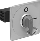 | 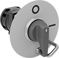 | 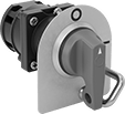 |
Style B | Style A | Style C |
Lockout—All switches have a lockout so you can secure them in the off position with a padlock (not included).
IP69K Enclosure Rating—Rated IP69K, these switches withstand high-pressure, high-temperature washdowns.
Switching | |||||||||||||||||
|---|---|---|---|---|---|---|---|---|---|---|---|---|---|---|---|---|---|
Style | Current, amp | Voltage, V AC | Switch Designation | Electrical Phase (hp) | Dia. | Ht. | Wd. | Dp. Behind Panel | For Max. Padlock Shackle Dia. | Wire Connection | Enclosure Rating | Certification | Specs. Met | Each | |||
Yellow Stainless Steel Housing with Red Actuator | |||||||||||||||||
2 Circuits Controlled with Lockout—For 7/8" Dia. Panel Cutouts | |||||||||||||||||
| A | 20 | 300 | DPST | Single (3/4 hp @ 120V AC) Single (2 hp @ 240V AC) Three (2 hp @ 240V AC) | 3 15/16" | — | — | 2 15/16" | 5/16" | Screw Terminal | IP69K | UL Listed, C-UL Listed, CE Marked | UL 508 | 6759K112 | 0000000 | ||
4 Circuits Controlled with Lockout—For 7/8" Dia. Panel Cutouts | |||||||||||||||||
| A | 20 | 300 | 4PST | Single (3/4 hp @ 120V AC) Single (2 hp @ 240V AC) Three (2 hp @ 240V AC) | 3 15/16" | — | — | 3 3/8" | 5/16" | Screw Terminal | IP69K | UL Listed, C-UL Listed, CE Marked | UL 508 | 6759K115 | 000000 | ||
Gray Stainless Steel Housing with Gray Actuator | |||||||||||||||||
2 Circuits Controlled with Lockout—For 7/8" Dia. Panel Cutouts | |||||||||||||||||
| C | 20 | 300 | DPST | Single (3/4 hp @ 120V AC) Single (2 hp @ 240V AC) Three (2 hp @ 240V AC) | — | 3 1/8" | 2 3/4" | 2 15/16" | 5/16" | Screw Terminal | IP69K | UL Listed, C-UL Listed, CE Marked | UL 508 | 6759K113 | 000000 | ||
4 Circuits Controlled with Lockout—For 7/8" Dia. Panel Cutouts | |||||||||||||||||
| C | 20 | 300 | 4PST | Single (3/4 hp @ 120V AC) Single (2 hp @ 240V AC) Three (2 hp @ 240V AC) | — | 3 1/8" | 2 3/4" | 3 3/8" | 5/16" | Screw Terminal | IP69K | UL Listed, C-UL Listed, CE Marked | UL 508 | 6759K116 | 000000 | ||
Compact Safety Limit Switches
 |  |
Style A | Style B |
 |  |
Style D | Style E |
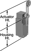
Shorter and thinner than other safety limit switches, these are sized to fit tight spaces. They protect machinery and ensure the safety of personnel. Positive-force contacts open the circuit when actuated, even if a spring fails or the contacts stick. They send a signal to your circuit when an object hits the actuator—for instance, a box on a conveyor runs into the switch, stopping the conveyor. They open and close circuits as fast as snap-acting switches, but they have a bigger actuator for large objects. All are NEMA and IP rated for protection from washdowns.
Plunger Actuator—Switches with a plunger actuator require a push to actuate, similar to a button.
Roller Plunger Actuator—Switches with a roller plunger actuator have a roller that moves parallel to the mounting direction when an object pushes the actuator. This reduces friction during actuation to limit wear and tear on your switch.
Roller Lever Actuator—Switches with a roller lever actuator use a lever with a roller at the end to activate. This allows parts to glide across the actuation surface with minimal friction, limiting wear and tear.
Style E—Styles E and F have an actuator that allows you to adjust its height, making it easier to align the switch with the target during installation.
NEMA 13 Enclosure Rating and IP67 Enclosure Rating—NEMA 13 and IP67 rated switches are protected from oil/coolant spraying and temporary submersion.
Housing | ||||||||||||||||||||
|---|---|---|---|---|---|---|---|---|---|---|---|---|---|---|---|---|---|---|---|---|
Style | No. of Circuits Controlled | Switch Starting Position | Switch Action | Switch Designation | Switching Current @ Voltage | Max. Voltage | Actuation Torque, in·ozf | Operating Temp. Range, ° F | Actuator Ht. | No. of Terminals | Lg. | Ht. | Dp. | Housing Material | Conduit Trade Size | Enclosure Rating | Each | |||
Plunger Actuator | ||||||||||||||||||||
Screw-Terminal Wire Connection | ||||||||||||||||||||
| A | 1 | 1 Off or 1 On | Momentary | SPDT | 10 amp @ 300V AC, 10 amp @ 250V DC | 300V AC 250V DC | — | -40 to 185 | 0.7" | 4 | 1.2" | 2.6" | 1.2" | Zinc | 1/2 | NEMA 4, NEMA 13, IP66, IP67 | 6352K41 | 000000 | ||
Roller Plunger Actuator | ||||||||||||||||||||
Screw-Terminal Wire Connection | ||||||||||||||||||||
| B | 1 | 1 Off or 1 On | Momentary | SPDT | 10 amp @ 300V AC, 10 amp @ 250V DC | 300V AC 250V DC | — | -40 to 185 | 1.1" | 4 | 1.2" | 2.6" | 1.2" | Zinc | 1/2 | NEMA 4, NEMA 13, IP66, IP67 | 6352K42 | 000000 | ||
Roller Lever Actuator | ||||||||||||||||||||
Screw-Terminal Wire Connection | ||||||||||||||||||||
| D | 1 | 1 Off or 1 On | Momentary | SPDT | 10 amp @ 300V AC, 10 amp @ 250V DC | 300V AC 250V DC | 17.6 | -40 to 185 | 2.1" | 4 | 1.2" | 2.6" | 1.2" | Zinc | 1/2 | NEMA 4, NEMA 13, IP66, IP67 | 6352K43 | 000000 | ||
| E | 1 | 1 Off or 1 On | Momentary | SPDT | 10 amp @ 300V AC, 10 amp @ 250V DC | 300V AC 250V DC | 17.6 | -40 to 185 | 1.6" to 3.3" | 4 | 1.2" | 2.6" | 1.2" | Zinc | 1/2 | NEMA 4, NEMA 13, IP66, IP67 | 6352K44 | 000000 | ||
Solid State Screw Terminal Relays
 | 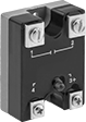 | 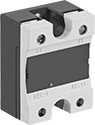 | 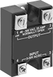 |
1-Circuit Relay with Covered Terminals and LED Indicator | 1-Circuit Relay with LED Indicator | 1-Circuit Relay with Covered Terminals | 1-Circuit Relay |
With no moving parts, these solid-state relays are fast switching and require less maintenance, last longer, and are quieter than mechanical switches.
Relays with High-Starting-Current Protection—Relays with high-starting-current protection are designed with integrated circuits that prevent damage from the large burst of electricity when a device, such as a motor or pump, turns on.
Switching Current @ Voltage | |||||||||||
|---|---|---|---|---|---|---|---|---|---|---|---|
No. of Terminals | Input Voltage | Without Heat Sink | With Heat Sink, amp | Max. Switching Voltage, V AC | Ht. | Wd. | Dp. | Each | |||
1 Circuit Controlled with 1 Off—SPST-NO | |||||||||||
Relays with High-Starting-Current Protection | |||||||||||
| 4 | 70V AC, 120V AC, 140V AC | 7.5 amp @ 300V AC | 25 | 300 | 2.3" | 1.8" | 1.1" | 7456K13 | 0000000 | ||
| 4 | 12V AC, 24V AC, 3V DC, 6V DC, 12V DC, 24V DC, 30V DC | 7.5 amp @ 300V AC | 25 | 300 | 2.3" | 1.8" | 1.1" | 7456K14 | 000000 | ||
1 Circuit Controlled with 1 On—SPST-NC | |||||||||||
Relays with High-Starting-Current Protection | |||||||||||
| 4 | 70V AC, 120V AC, 140V AC | 7.5 amp @ 300V AC | 25 | 300 | 2.3" | 1.8" | 1.1" | 7456K15 | 000000 | ||
| 4 | 12V AC, 24V AC, 3V DC, 6V DC, 12V DC, 24V DC, 30V DC | 7.5 amp @ 300V AC | 25 | 300 | 2.3" | 1.8" | 1.1" | 7456K16 | 000000 | ||
Hazardous Location Relays
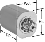 | 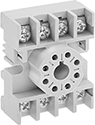 |
Circular-Pin Terminals—Hermetically Sealed | Sockets with Screw Terminals |
Sealed for safety, these relays are a good choice for hazardous locations where combustible or corrosive gases may be present.
Circular-Pin Terminal—Relays with circular-pin terminals or quick-disconnect terminals are hermetically sealed—completely air- and watertight—to shield internal parts from gases, moisture, and other contaminants. They plug into relay sockets (sold separately) for easy installation.
Sockets with Screw Terminals—Relay sockets mount to 35 mm DIN rail (also known as DIN 3 rail) or flat surfaces.
Relays | Sockets with Screw Terminals | ||||||||||||||
|---|---|---|---|---|---|---|---|---|---|---|---|---|---|---|---|
No. of Terminals | Input Voltage | Control Current, mA | Switching Current @ Voltage | Max. Switching Voltage, V AC | hp @ Switching Voltage | Ht. | Wd. | Dp. | Hazardous Location Rating | Each | Each | ||||
Circular-Pin Terminals—Hermetically Sealed | |||||||||||||||
2 Circuits Controlled with 2 Off or 2 On—DPDT | |||||||||||||||
| 8 | 120V AC | 10 | 12 amp @ 120V AC/24V DC | 300 | 1/3 hp @ 120V AC | 1.6" | 1.4" | 2.1" | NEC Class I Division 2 Groups A, B, C, D | 7125T32 | 0000000 | 7125T41 | 00000 | ||
| 8 | 24V DC | 38 | 12 amp @ 120V AC/24V DC | 300 | 1/3 hp @ 120V AC | 1.6" | 1.4" | 2.1" | NEC Class I Division 2 Groups A, B, C, D | 7125T34 | 000000 | 7125T41 | 0000 | ||
3 Circuits Controlled with 3 Off or 3 On—3PDT | |||||||||||||||
| 11 | 120V AC | 100 | 12 amp @ 120V AC/240V AC | 300 | 1/3 hp @ 120V AC | 1.6" | 1.4" | 2.1" | NEC Class I Division 2 Groups A, B, C, D | 7125T111 | 000000 | 7122K21 | 0000 | ||
