


Filter by
System of Measurement
Switching Voltage
Alert Type
Switch Starting Position
Material
Number of Circuits Controlled
Switch Action
DFARS Specialty Metals
Export Control Classification Number (ECCN)
Measures
Electrical Connection
U.S.–Mexico–Canada Agreement (USMCA) Qualifying
Conduit Gender
Conduit Thread Type
Conduit Trade Size
Hazardous Location Vibration Switches
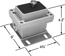 |
Get NEMA 4 and IP66 protection from dirt and water. These switches are rated for hazardous locations for Class I, Divisions 1 and 2, Groups C and D; and Class II, Divisions 1 and 2, Groups E, F, and G. If vibration or shock exceeds a set activation point, the contacts actuate to either shut down your machine or activate an alarm. Reset the switch with the push of a button. The activation point is adjustable between 0 to 5 gravity units (g) at 0 to 60 Hz.
Activation Point | Switching | Housing | Conduit | Mounting Slot | |||||||||||||||||
|---|---|---|---|---|---|---|---|---|---|---|---|---|---|---|---|---|---|---|---|---|---|
Range, g | Freq. Range, Hz | Current, amp | Voltage, V AC | Ht. | Wd. | Dp. | Temp. Range, ° F | Trade Size | Thread Type | Gender | Mounting Fasteners Included | No. of Mounting Holes | Lg. | Wd. | Hazardous Location Rating | Enclosure Rating | Certification | Each | |||
1 Off or 1 On Switch Starting Position | |||||||||||||||||||||
SPDT | |||||||||||||||||||||
| 0 to 5 | 0 to 60 | 15 | 125 480 | 4.2" | 4 3/4" | 6" | -40 to 155 | 3/4 | NPT | Female | No | 4 | 3/4" | 3/8" | NEC Class I Divisions 1, 2 Groups C, D NEC Class II Divisions 1, 2 Groups E, F, G | IP66 NEMA 4 | UL Listed, C-UL Listed, CSA-US Certified, CSA Certified, CE Marked | 1188T31 | 0000000 | ||
Analog-Input Proportional-Control Relays
 |
1 Circuit Controlled |
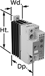
Often used to regulate the speed of AC fans or keep a heater at a set temperature, these relays connect directly to sensors to calculate and adjust output power. This allows you to use an analog input without converting it to a digital signal to control output power. They are solid state and have no moving parts, so they require less maintenance and last longer, are quieter, and switch faster than mechanical relays. IP20 rated, they have recessed terminals that prevent fingers and other objects from touching live circuits. An integrated heat sink disperses heat to increase the relay’s current rating. The LED indicator shows input voltage loss and internal relay faults, so you can easily check that your system is operating properly.
Mount them on 35 mm DIN rail (also known as DIN 3 rail) for fast installation. They also mount to flat surfaces.
All relays have phase-angle switching to accurately control all types of loads. This mode signals at non-zero voltage, which can produce electrical noise.
Single Phase—Single-phase relays can be set to switch every 1, 4, or 16 cycles. When used with infrared heaters, they have an option to switch at the half cycle and again at the full cycle. When switching at 16 cycles or at the half cycle, these relays have a soft-start option to increase the output slower in high-inrush current applications.
Potentiometer Input—Relays with a potentiometer input can connect to an external potentiometer for manual control.
Input | Output | |||||||||||||||
|---|---|---|---|---|---|---|---|---|---|---|---|---|---|---|---|---|
No. of Terminals | Analog Signal | No. of | Voltage, V AC | Current, amp | No. of | Control Current, mA | Switching Current @ Voltage | Max. Switching Voltage, V AC | Ht. | Wd. | Dp. | Features | Each | |||
1 Circuit Controlled with 1 Off—SPST-NO | ||||||||||||||||
Single Phase with Phase Angle Switching Mode | ||||||||||||||||
| 4 | 4 mA to 20 mA | 1 | 190 to 550 | 30 | 1 | 50 | 30 amp @ 480V AC | 550 | 4.33" | 1.4" | 4.08" | Integrated Heat Sink, LED Indicator, Recessed Terminals | 7048N12 | 0000000 | ||
| 4 | 4 mA to 20 mA | 1 | 190 to 550 | 42 | 1 | 50 | 42 amp @ 480V AC | 550 | 4.33" | 1.4" | 4.08" | Integrated Heat Sink, LED Indicator, Recessed Terminals | 7048N14 | 000000 | ||
| 9 | 0V DC to 10V DC | 1 | 190 to 550 | 30 | 1 | 50 | 30 amp @ 480V AC | 550 | 4.33" | 1.4" | 4.08" | Integrated Heat Sink, LED Indicator, Recessed Terminals, Potentiometer Input | 7048N17 | 000000 | ||
| 9 | 0V DC to 10V DC | 1 | 190 to 550 | 42 | 1 | 50 | 42 amp @ 480V AC | 550 | 4.33" | 1.4" | 4.08" | Integrated Heat Sink, LED Indicator, Recessed Terminals, Potentiometer Input | 7048N18 | 000000 | ||
Solid State Screw Terminal Relays
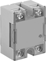 | 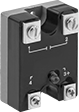 | 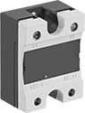 |
1-Circuit Relay with Covered Terminals and LED Indicator | 1-Circuit Relay with LED Indicator | 1-Circuit Relay with Covered Terminals |
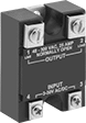 | 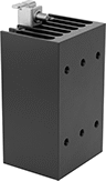 | |
1-Circuit Relay | Heat Sinks |
With no moving parts, these solid-state relays are fast switching and require less maintenance, last longer, and are quieter than mechanical switches.
High-Starting-Current Protection—Relays with high-starting-current protection are designed with integrated circuits that prevent damage from the large burst of electricity when a device, such as a motor or pump, turns on.
Heat Sinks—Heat sinks disperse heat to increase the relay’s current rating. Mount them to 35 mm DIN rail (also known as DIN 3 rail) for fast installation. They also mount to flat surfaces. Before mounting one-circuit relays, silicone compound or a thermal pad should be placed between the heat sink and relay. Silicone compound is sold separately for heat sinks that do not include it but require it. Two-circuit relays don’t require silicone for mounting.
Relays | Heat Sinks | |||||||||||||
|---|---|---|---|---|---|---|---|---|---|---|---|---|---|---|
Switching Current @ Voltage | ||||||||||||||
No. of Terminals | Input Voltage | Without Heat Sink | With Heat Sink, amp | Max. Switching Voltage, V AC | Ht. | Wd. | Dp. | Enclosure Rating | Each | Each | ||||
1 Circuit Controlled with 1 Off—SPST-NO | ||||||||||||||
Relays with High-Starting-Current Protection and Covered Terminals | ||||||||||||||
| 4 | 24V AC, 48V AC, 120V AC, 240V AC, 24V DC, 48V DC | 2.5 amp @ 480V AC | 25 | 530 | 2.3" | 1.8" | 1.1" | IP20 | 7456K106 | 000000 | 7456K33 | 000000 | ||
| 4 | 24V AC, 48V AC, 120V AC, 240V AC, 24V DC, 48V DC | 5 amp @ 480V AC | 50 | 530 | 2.3" | 1.8" | 1.1" | IP20 | 7456K108 | 00000 | 7456K33 | 00000 | ||
| 4 | 24V AC, 48V AC, 120V AC, 240V AC, 24V DC, 48V DC | 7.5 amp @ 480V AC | 75 | 530 | 2.3" | 1.8" | 1.1" | IP20 | 7456K111 | 000000 | 7456K33 | 00000 | ||
| 4 | 24V AC, 48V AC, 120V AC, 240V AC, 24V DC, 48V DC | 10 amp @ 480V AC | 100 | 530 | 2.3" | 1.8" | 1.1" | IP20 | 7456K113 | 000000 | 7456K33 | 00000 | ||
| 4 | 4V DC, 6V DC, 12V DC, 24V DC, 30V DC | 2.5 amp @ 480V AC | 25 | 530 | 2.3" | 1.8" | 1.1" | IP20 | 7456K105 | 00000 | 7456K33 | 00000 | ||
| 4 | 4V DC, 6V DC, 12V DC, 24V DC, 30V DC | 5 amp @ 480V AC | 50 | 530 | 2.3" | 1.8" | 1.1" | IP20 | 7456K107 | 00000 | 7456K33 | 00000 | ||
| 4 | 4V DC, 6V DC, 12V DC, 24V DC, 30V DC | 7.5 amp @ 480V AC | 75 | 530 | 2.3" | 1.8" | 1.1" | IP20 | 7456K109 | 000000 | 7456K33 | 00000 | ||
| 4 | 4V DC, 6V DC, 12V DC, 24V DC, 30V DC | 10 amp @ 480V AC | 100 | 530 | 2.3" | 1.8" | 1.1" | IP20 | 7456K112 | 000000 | 7456K33 | 00000 | ||
