Filter by
Product Family
Threaded Insert Type
Thread Size
Installed Length

For Use In
Hole Diameter
For Material Thickness

Drill Bit Size
Thread Fit

Thread Direction
Sold As
Threaded Insert Securing Type
DFARS Specialty Metals
Export Control Classification Number (ECCN)

About Threaded Inserts
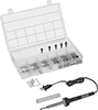
Choose the right threaded insert for your application and learn how to install it securely.
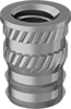
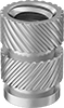
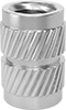
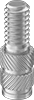
Threaded Inserts
Heat-Set Inserts