


Filter by
Input Voltage
Timing Adjustment Style

Timer Function
Overall Timing
Number of Circuits Controlled
Wire Connection

Operation Type
Relay Type

Switch Starting Position
Export Control Classification Number (ECCN)
DFARS Specialty Metals
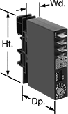
Solid State Surface-Mount Timer Relays
 |
Timing Range | |||||||||||||||||||||||||||||||||||||||||||||||||||||||||||||||||||||||||||||||||||||||||||||||||||
|---|---|---|---|---|---|---|---|---|---|---|---|---|---|---|---|---|---|---|---|---|---|---|---|---|---|---|---|---|---|---|---|---|---|---|---|---|---|---|---|---|---|---|---|---|---|---|---|---|---|---|---|---|---|---|---|---|---|---|---|---|---|---|---|---|---|---|---|---|---|---|---|---|---|---|---|---|---|---|---|---|---|---|---|---|---|---|---|---|---|---|---|---|---|---|---|---|---|---|---|
No. of Terminals | Input Voltage | Control Current, mA | No. of | Overall | Switching Current @ Voltage | Max. Switching Voltage, V AC | hp @ Switching Voltage | Ht. | Wd. | Dp. | Features | Each | |||||||||||||||||||||||||||||||||||||||||||||||||||||||||||||||||||||||||||||||||||||||
Delayed Start (Delay on Make) | |||||||||||||||||||||||||||||||||||||||||||||||||||||||||||||||||||||||||||||||||||||||||||||||||||
1 Circuit Controlled with 1 Off—SPST-NO | |||||||||||||||||||||||||||||||||||||||||||||||||||||||||||||||||||||||||||||||||||||||||||||||||||
| 2 | 12V AC, 12V DC | 21 | 1 | 0.05 sec. to 1 sec. | 1 amp @ 120V AC | — | — | 2" | 2" | 0.89" | Potentiometer | 77055K731 | 0000000 | ||||||||||||||||||||||||||||||||||||||||||||||||||||||||||||||||||||||||||||||||||||||
| 2 | 12V AC, 12V DC | 21 | 1 | 0.25 sec. to 5 sec. | 1 amp @ 120V AC | — | — | 2" | 2" | 0.89" | Potentiometer | 77055K732 | 000000 | ||||||||||||||||||||||||||||||||||||||||||||||||||||||||||||||||||||||||||||||||||||||
| 2 | 12V AC, 12V DC | 21 | 1 | 0.5 sec. to 10 sec. | 1 amp @ 120V AC | — | — | 2" | 2" | 0.89" | Potentiometer | 77055K733 | 000000 | ||||||||||||||||||||||||||||||||||||||||||||||||||||||||||||||||||||||||||||||||||||||
| 2 | 12V AC, 12V DC | 21 | 1 | 3 sec. to 60 sec. | 1 amp @ 120V AC | — | — | 2" | 2" | 0.89" | Potentiometer | 77055K734 | 000000 | ||||||||||||||||||||||||||||||||||||||||||||||||||||||||||||||||||||||||||||||||||||||
| 2 | 12V AC, 12V DC | 21 | 1 | 15 sec. to 300 sec. | 1 amp @ 120V AC | — | — | 2" | 2" | 0.89" | Potentiometer | 77055K735 | 000000 | ||||||||||||||||||||||||||||||||||||||||||||||||||||||||||||||||||||||||||||||||||||||
| 2 | 12V AC, 12V DC | 21 | 1 | 30 sec. to 10 min. | 1 amp @ 120V AC | — | — | 2" | 2" | 0.89" | Potentiometer | 77055K736 | 000000 | ||||||||||||||||||||||||||||||||||||||||||||||||||||||||||||||||||||||||||||||||||||||
| 2 | 24V AC, 24V DC | 10 | 1 | 0.05 sec. to 1 sec. | 1 amp @ 120V AC | — | — | 2" | 2" | 0.89" | Potentiometer | 77055K751 | 000000 | ||||||||||||||||||||||||||||||||||||||||||||||||||||||||||||||||||||||||||||||||||||||
| 2 | 24V AC, 24V DC | 10 | 1 | 0.25 sec. to 5 sec. | 1 amp @ 120V AC | — | — | 2" | 2" | 0.89" | Potentiometer | 77055K752 | 000000 | ||||||||||||||||||||||||||||||||||||||||||||||||||||||||||||||||||||||||||||||||||||||
| 2 | 24V AC, 24V DC | 10 | 1 | 0.5 sec. to 10 sec. | 1 amp @ 120V AC | — | — | 2" | 2" | 0.89" | Potentiometer | 77055K753 | 000000 | ||||||||||||||||||||||||||||||||||||||||||||||||||||||||||||||||||||||||||||||||||||||
| 2 | 24V AC, 24V DC | 10 | 1 | 3 sec. to 60 sec. | 1 amp @ 120V AC | — | — | 2" | 2" | 0.89" | Potentiometer | 77055K754 | 000000 | ||||||||||||||||||||||||||||||||||||||||||||||||||||||||||||||||||||||||||||||||||||||
| 2 | 24V AC, 24V DC | 10 | 1 | 15 sec. to 300 sec. | 1 amp @ 120V AC | — | — | 2" | 2" | 0.89" | Potentiometer | 77055K755 | 000000 | ||||||||||||||||||||||||||||||||||||||||||||||||||||||||||||||||||||||||||||||||||||||
| 2 | 24V AC, 24V DC | 10 | 1 | 30 sec. to 10 min. | 1 amp @ 120V AC | — | — | 2" | 2" | 0.89" | Potentiometer | 77055K756 | 000000 | ||||||||||||||||||||||||||||||||||||||||||||||||||||||||||||||||||||||||||||||||||||||
| 2 | 120V AC, 120V DC | 4 | 1 | 0.05 sec. to 1 sec. | 1 amp @ 120V AC | — | — | 2" | 2" | 0.89" | Potentiometer | 77055K25 | 000000 | ||||||||||||||||||||||||||||||||||||||||||||||||||||||||||||||||||||||||||||||||||||||
| 2 | 120V AC, 120V DC | 4 | 1 | 0.25 sec. to 5 sec. | 1 amp @ 120V AC | — | — | 2" | 2" | 0.89" | Potentiometer | 77055K26 | 000000 | ||||||||||||||||||||||||||||||||||||||||||||||||||||||||||||||||||||||||||||||||||||||
| 2 | 120V AC, 120V DC | 4 | 1 | 0.5 sec. to 10 sec. | 1 amp @ 120V AC | — | — | 2" | 2" | 0.89" | Potentiometer | 77055K27 | 000000 | ||||||||||||||||||||||||||||||||||||||||||||||||||||||||||||||||||||||||||||||||||||||
| 2 | 120V AC, 120V DC | 4 | 1 | 3 sec. to 60 sec. | 1 amp @ 120V AC | — | — | 2" | 2" | 0.89" | Potentiometer | 77055K28 | 000000 | ||||||||||||||||||||||||||||||||||||||||||||||||||||||||||||||||||||||||||||||||||||||
| 2 | 120V AC, 120V DC | 4 | 1 | 15 sec. to 300 sec. | 1 amp @ 120V AC | — | — | 2" | 2" | 0.89" | Potentiometer | 77055K29 | 000000 | ||||||||||||||||||||||||||||||||||||||||||||||||||||||||||||||||||||||||||||||||||||||
| 2 | 120V AC, 120V DC | 4 | 1 | 30 sec. to 10 min. | 1 amp @ 120V AC | — | — | 2" | 2" | 0.89" | Potentiometer | 77055K31 | 000000 | ||||||||||||||||||||||||||||||||||||||||||||||||||||||||||||||||||||||||||||||||||||||
| 2 | 24V AC to 240V AC/24V DC to 240V DC | 10 | 1 | 1 sec. to 1,023 sec. | 1 amp @ 120V AC | — | — | 2" | 2" | 0.89" | Potentiometer | 77055K74 | 000000 | ||||||||||||||||||||||||||||||||||||||||||||||||||||||||||||||||||||||||||||||||||||||
1 Circuit Controlled with 1 Off or 1 On—SPDT | |||||||||||||||||||||||||||||||||||||||||||||||||||||||||||||||||||||||||||||||||||||||||||||||||||
| 5 | 120V AC | 29 | 1 | 0.05 sec. to 1 sec. | 8 amp @ 240V AC | — | — | 2" | 2" | 0.9" | — | 77055K45 | 000000 | ||||||||||||||||||||||||||||||||||||||||||||||||||||||||||||||||||||||||||||||||||||||
| 5 | 120V AC | 29 | 1 | 0.25 sec. to 5 sec. | 8 amp @ 240V AC | — | — | 2" | 2" | 0.9" | — | 77055K46 | 000000 | ||||||||||||||||||||||||||||||||||||||||||||||||||||||||||||||||||||||||||||||||||||||
| 5 | 120V AC | 29 | 1 | 0.5 sec. to 10 sec. | 8 amp @ 240V AC | — | — | 2" | 2" | 0.9" | — | 77055K47 | 000000 | ||||||||||||||||||||||||||||||||||||||||||||||||||||||||||||||||||||||||||||||||||||||
| 5 | 120V AC | 29 | 1 | 3 sec. to 60 sec. | 8 amp @ 240V AC | — | — | 2" | 2" | 0.9" | — | 77055K48 | 000000 | ||||||||||||||||||||||||||||||||||||||||||||||||||||||||||||||||||||||||||||||||||||||
| 5 | 120V AC | 29 | 1 | 15 sec. to 300 sec. | 8 amp @ 240V AC | — | — | 2" | 2" | 0.9" | — | 77055K49 | 000000 | ||||||||||||||||||||||||||||||||||||||||||||||||||||||||||||||||||||||||||||||||||||||
| 5 | 120V AC | 29 | 1 | 30 sec. to 10 min. | 8 amp @ 240V AC | — | — | 2" | 2" | 0.9" | — | 77055K51 | 000000 | ||||||||||||||||||||||||||||||||||||||||||||||||||||||||||||||||||||||||||||||||||||||
| 5 | 120V AC | 36 | 1 | 0.1 sec. to 10 sec. | 30 amp @ 240V AC/24V DC | 240 | 1 hp @ 120V AC 2 hp @ 240V AC | 3" | 2" | 1.4" | — | 2809T151 | 00000 | ||||||||||||||||||||||||||||||||||||||||||||||||||||||||||||||||||||||||||||||||||||||
| 5 | 120V AC | 36 | 1 | 0.1 min. to 10 min. | 30 amp @ 240V AC/24V DC | 240 | 1 hp @ 120V AC 2 hp @ 240V AC | 3" | 2" | 1.4" | — | 2809T154 | 00000 | ||||||||||||||||||||||||||||||||||||||||||||||||||||||||||||||||||||||||||||||||||||||
| 5 | 120V AC | 36 | 1 | 1 min. to 100 min. | 30 amp @ 240V AC/24V DC | 240 | 1 hp @ 120V AC 2 hp @ 240V AC | 3" | 2" | 1.4" | — | 2809T155 | 00000 | ||||||||||||||||||||||||||||||||||||||||||||||||||||||||||||||||||||||||||||||||||||||
| 5 | 12V DC | 292 | 1 | 3 sec. to 60 sec. | 8 amp @ 240V AC | — | — | 2" | 2" | 0.9" | — | 77055K631 | 000000 | ||||||||||||||||||||||||||||||||||||||||||||||||||||||||||||||||||||||||||||||||||||||
| 5 | 12V DC | 292 | 1 | 15 sec. to 300 sec. | 8 amp @ 240V AC | — | — | 2" | 2" | 0.9" | — | 77055K632 | 000000 | ||||||||||||||||||||||||||||||||||||||||||||||||||||||||||||||||||||||||||||||||||||||
| 5 | 24V DC | 41 | 1 | 0.1 sec. to 10 sec. | 30 amp @ 240V AC/24V DC | 240 | 1 hp @ 120V AC 2 hp @ 240V AC | 3" | 2" | 1.4" | — | 2809T161 | 00000 | ||||||||||||||||||||||||||||||||||||||||||||||||||||||||||||||||||||||||||||||||||||||
| 5 | 24V DC | 41 | 1 | 0.1 min. to 10 min. | 30 amp @ 240V AC/24V DC | 240 | 1 hp @ 120V AC 2 hp @ 240V AC | 3" | 2" | 1.4" | — | 2809T164 | 00000 | ||||||||||||||||||||||||||||||||||||||||||||||||||||||||||||||||||||||||||||||||||||||
| 5 | 24V DC | 41 | 1 | 1 min. to 100 min. | 30 amp @ 240V AC/24V DC | 240 | 1 hp @ 120V AC 2 hp @ 240V AC | 3" | 2" | 1.4" | — | 2809T165 | 00000 | ||||||||||||||||||||||||||||||||||||||||||||||||||||||||||||||||||||||||||||||||||||||
Delayed Switch Off (Delay on Break) | |||||||||||||||||||||||||||||||||||||||||||||||||||||||||||||||||||||||||||||||||||||||||||||||||||
1 Circuit Controlled with 1 Off—SPST-NO | |||||||||||||||||||||||||||||||||||||||||||||||||||||||||||||||||||||||||||||||||||||||||||||||||||
| 5 | 120V AC | 36 | 1 | 0.05 sec. to 1 sec. | 1 amp @ 120V AC | — | — | 2" | 2" | 0.88" | Potentiometer | 7457K33 | 00000 | ||||||||||||||||||||||||||||||||||||||||||||||||||||||||||||||||||||||||||||||||||||||
| 5 | 120V AC | 36 | 1 | 0.25 sec. to 5 sec. | 1 amp @ 120V AC | — | — | 2" | 2" | 0.88" | Potentiometer | 7457K34 | 00000 | ||||||||||||||||||||||||||||||||||||||||||||||||||||||||||||||||||||||||||||||||||||||
| 5 | 120V AC | 36 | 1 | 0.5 sec. to 10 sec. | 1 amp @ 120V AC | — | — | 2" | 2" | 0.88" | Potentiometer | 7457K35 | 00000 | ||||||||||||||||||||||||||||||||||||||||||||||||||||||||||||||||||||||||||||||||||||||
| 5 | 120V AC | 36 | 1 | 3 sec. to 60 sec. | 1 amp @ 120V AC | — | — | 2" | 2" | 0.88" | Potentiometer | 7457K36 | 00000 | ||||||||||||||||||||||||||||||||||||||||||||||||||||||||||||||||||||||||||||||||||||||
| 5 | 120V AC | 36 | 1 | 15 sec. to 300 sec. | 1 amp @ 120V AC | — | — | 2" | 2" | 0.88" | Potentiometer | 7457K37 | 00000 | ||||||||||||||||||||||||||||||||||||||||||||||||||||||||||||||||||||||||||||||||||||||
| 5 | 120V AC | 36 | 1 | 30 sec. to 10 min. | 1 amp @ 120V AC | — | — | 2" | 2" | 0.88" | Potentiometer | 7457K38 | 00000 | ||||||||||||||||||||||||||||||||||||||||||||||||||||||||||||||||||||||||||||||||||||||
| 7 | 12V DC | 217 | 1 | 0.25 sec. to 5 sec. | 1 amp @ 120V AC | — | — | 2" | 2" | 0.88" | — | 7457K522 | 00000 | ||||||||||||||||||||||||||||||||||||||||||||||||||||||||||||||||||||||||||||||||||||||
| 7 | 12V DC | 217 | 1 | 3 sec. to 60 sec. | 1 amp @ 120V AC | — | — | 2" | 2" | 0.88" | — | 7457K524 | 00000 | ||||||||||||||||||||||||||||||||||||||||||||||||||||||||||||||||||||||||||||||||||||||
1 Circuit Controlled with 1 Off or 1 On—SPDT | |||||||||||||||||||||||||||||||||||||||||||||||||||||||||||||||||||||||||||||||||||||||||||||||||||
| 6 | 120V AC | 36 | 1 | 0.1 sec. to 10 sec. | 30 amp @ 240V AC/24V DC | 240 | 1 hp @ 120V AC 2 hp @ 240V AC | 3" | 2" | 1.4" | — | 2809T451 | 00000 | ||||||||||||||||||||||||||||||||||||||||||||||||||||||||||||||||||||||||||||||||||||||
| 6 | 120V AC | 36 | 1 | 0.1 min. to 10 min. | 30 amp @ 240V AC/24V DC | 240 | 1 hp @ 120V AC 2 hp @ 240V AC | 3" | 2" | 1.4" | — | 2809T454 | 00000 | ||||||||||||||||||||||||||||||||||||||||||||||||||||||||||||||||||||||||||||||||||||||
| 6 | 120V AC | 36 | 1 | 1 min. to 100 min. | 30 amp @ 240V AC/24V DC | 240 | 1 hp @ 120V AC 2 hp @ 240V AC | 3" | 2" | 1.4" | — | 2809T455 | 00000 | ||||||||||||||||||||||||||||||||||||||||||||||||||||||||||||||||||||||||||||||||||||||
| 6 | 24V DC | 41 | 1 | 0.1 sec. to 10 sec. | 30 amp @ 240V AC/24V DC | 240 | 1 hp @ 120V AC 2 hp @ 240V AC | 3" | 2" | 1.4" | — | 2809T461 | 00000 | ||||||||||||||||||||||||||||||||||||||||||||||||||||||||||||||||||||||||||||||||||||||
| 6 | 24V DC | 41 | 1 | 0.1 min. to 10 min. | 30 amp @ 240V AC/24V DC | 240 | 1 hp @ 120V AC 2 hp @ 240V AC | 3" | 2" | 1.4" | — | 2809T464 | 00000 | ||||||||||||||||||||||||||||||||||||||||||||||||||||||||||||||||||||||||||||||||||||||
| 6 | 24V DC | 41 | 1 | 1 min. to 100 min. | 30 amp @ 240V AC/24V DC | 240 | 1 hp @ 120V AC 2 hp @ 240V AC | 3" | 2" | 1.4" | — | 2809T465 | 00000 | ||||||||||||||||||||||||||||||||||||||||||||||||||||||||||||||||||||||||||||||||||||||
Interval | |||||||||||||||||||||||||||||||||||||||||||||||||||||||||||||||||||||||||||||||||||||||||||||||||||
1 Circuit Controlled with 1 Off—SPST-NO | |||||||||||||||||||||||||||||||||||||||||||||||||||||||||||||||||||||||||||||||||||||||||||||||||||
| 5 | 120V AC | 25 | 1 | 0.05 sec. to 1 sec. | 1 amp @ 120V AC | — | — | 2" | 2" | 0.88" | — | 7457K651 | 000000 | ||||||||||||||||||||||||||||||||||||||||||||||||||||||||||||||||||||||||||||||||||||||
| 5 | 120V AC | 25 | 1 | 3 sec. to 60 sec. | 1 amp @ 120V AC | — | — | 2" | 2" | 0.88" | — | 7457K654 | 000000 | ||||||||||||||||||||||||||||||||||||||||||||||||||||||||||||||||||||||||||||||||||||||
| 5 | 120V AC | 25 | 1 | 30 sec. to 10 min. | 1 amp @ 120V AC | — | — | 2" | 2" | 0.88" | — | 7457K656 | 000000 | ||||||||||||||||||||||||||||||||||||||||||||||||||||||||||||||||||||||||||||||||||||||
1 Circuit Controlled with 1 Off or 1 On—SPDT | |||||||||||||||||||||||||||||||||||||||||||||||||||||||||||||||||||||||||||||||||||||||||||||||||||
| 5 | 120V AC | 36 | 1 | 0.1 sec. to 10 sec. | 30 amp @ 240V AC/24V DC | 240 | 1 hp @ 120V AC 2 hp @ 240V AC | 3" | 2" | 1.4" | — | 2809T251 | 00000 | ||||||||||||||||||||||||||||||||||||||||||||||||||||||||||||||||||||||||||||||||||||||
| 5 | 120V AC | 36 | 1 | 0.1 min. to 10 min. | 30 amp @ 240V AC/24V DC | 240 | 1 hp @ 120V AC 2 hp @ 240V AC | 3" | 2" | 1.4" | — | 2809T254 | 00000 | ||||||||||||||||||||||||||||||||||||||||||||||||||||||||||||||||||||||||||||||||||||||
| 5 | 120V AC | 36 | 1 | 1 min. to 100 min. | 30 amp @ 240V AC/24V DC | 240 | 1 hp @ 120V AC 2 hp @ 240V AC | 3" | 2" | 1.4" | — | 2809T255 | 00000 | ||||||||||||||||||||||||||||||||||||||||||||||||||||||||||||||||||||||||||||||||||||||
| 5 | 24V DC | 41 | 1 | 0.1 sec. to 10 sec. | 30 amp @ 240V AC/24V DC | 240 | 1 hp @ 120V AC 2 hp @ 240V AC | 3" | 2" | 1.4" | — | 2809T261 | 00000 | ||||||||||||||||||||||||||||||||||||||||||||||||||||||||||||||||||||||||||||||||||||||
| 5 | 24V DC | 41 | 1 | 0.1 min. to 10 min. | 30 amp @ 240V AC/24V DC | 240 | 1 hp @ 120V AC 2 hp @ 240V AC | 3" | 2" | 1.4" | — | 2809T264 | 00000 | ||||||||||||||||||||||||||||||||||||||||||||||||||||||||||||||||||||||||||||||||||||||
| 5 | 24V DC | 41 | 1 | 1 min. to 100 min. | 30 amp @ 240V AC/24V DC | 240 | 1 hp @ 120V AC 2 hp @ 240V AC | 3" | 2" | 1.4" | — | 2809T265 | 00000 | ||||||||||||||||||||||||||||||||||||||||||||||||||||||||||||||||||||||||||||||||||||||
Repeat Cycle | |||||||||||||||||||||||||||||||||||||||||||||||||||||||||||||||||||||||||||||||||||||||||||||||||||
1 Circuit Controlled with 1 Off—SPST-NO | |||||||||||||||||||||||||||||||||||||||||||||||||||||||||||||||||||||||||||||||||||||||||||||||||||
| 7 | 120V AC | 36 | 1 | 0.05 sec. to 1 sec. | 1 amp @ 120V AC | — | — | 2" | 2" | 0.88" | — | 7457K661 | 000000 | ||||||||||||||||||||||||||||||||||||||||||||||||||||||||||||||||||||||||||||||||||||||
| 7 | 120V AC | 36 | 1 | 3 sec. to 60 sec. | 1 amp @ 120V AC | — | — | 2" | 2" | 0.88" | — | 7457K664 | 000000 | ||||||||||||||||||||||||||||||||||||||||||||||||||||||||||||||||||||||||||||||||||||||
| 7 | 120V AC | 36 | 1 | 30 sec. to 10 min. | 1 amp @ 120V AC | — | — | 2" | 2" | 0.88" | — | 7457K666 | 000000 | ||||||||||||||||||||||||||||||||||||||||||||||||||||||||||||||||||||||||||||||||||||||
1 Circuit Controlled with 1 Off or 1 On—SPDT | |||||||||||||||||||||||||||||||||||||||||||||||||||||||||||||||||||||||||||||||||||||||||||||||||||
| 5 | 120V AC | 36 | 1 | 0.1 sec. to 10 sec. | 30 amp @ 240V AC/24V DC | 240 | 1 hp @ 120V AC 2 hp @ 240V AC | 3" | 2" | 1.4" | — | 2809T551 | 00000 | ||||||||||||||||||||||||||||||||||||||||||||||||||||||||||||||||||||||||||||||||||||||
| 5 | 120V AC | 36 | 1 | 0.1 min. to 10 min. | 30 amp @ 240V AC/24V DC | 240 | 1 hp @ 120V AC 2 hp @ 240V AC | 3" | 2" | 1.4" | — | 2809T554 | 00000 | ||||||||||||||||||||||||||||||||||||||||||||||||||||||||||||||||||||||||||||||||||||||
| 5 | 120V AC | 36 | 1 | 1 min. to 100 min. | 30 amp @ 240V AC/24V DC | 240 | 1 hp @ 120V AC 2 hp @ 240V AC | 3" | 2" | 1.4" | — | 2809T555 | 00000 | ||||||||||||||||||||||||||||||||||||||||||||||||||||||||||||||||||||||||||||||||||||||
| 5 | 24V DC | 41 | 1 | 0.1 sec. to 10 sec. | 30 amp @ 240V AC/24V DC | 240 | 1 hp @ 120V AC 2 hp @ 240V AC | 3" | 2" | 1.4" | — | 2809T561 | 00000 | ||||||||||||||||||||||||||||||||||||||||||||||||||||||||||||||||||||||||||||||||||||||
| 5 | 24V DC | 41 | 1 | 0.1 min. to 10 min. | 30 amp @ 240V AC/24V DC | 240 | 1 hp @ 120V AC 2 hp @ 240V AC | 3" | 2" | 1.4" | — | 2809T564 | 00000 | ||||||||||||||||||||||||||||||||||||||||||||||||||||||||||||||||||||||||||||||||||||||
| 5 | 24V DC | 41 | 1 | 1 min. to 100 min. | 30 amp @ 240V AC/24V DC | 240 | 1 hp @ 120V AC 2 hp @ 240V AC | 3" | 2" | 1.4" | — | 2809T565 | 00000 | ||||||||||||||||||||||||||||||||||||||||||||||||||||||||||||||||||||||||||||||||||||||
Switch on (Single Shot) | |||||||||||||||||||||||||||||||||||||||||||||||||||||||||||||||||||||||||||||||||||||||||||||||||||
1 Circuit Controlled with 1 Off—SPST-NO | |||||||||||||||||||||||||||||||||||||||||||||||||||||||||||||||||||||||||||||||||||||||||||||||||||
| 5 | 120V AC | 36 | 1 | 0.05 sec. to 1 sec. | 1 amp @ 120V AC | — | — | 2" | 2" | 0.88" | Potentiometer | 7457K641 | 000000 | ||||||||||||||||||||||||||||||||||||||||||||||||||||||||||||||||||||||||||||||||||||||
| 5 | 120V AC | 36 | 1 | 0.25 sec. to 5 sec. | 1 amp @ 120V AC | — | — | 2" | 2" | 0.88" | Potentiometer | 7457K642 | 000000 | ||||||||||||||||||||||||||||||||||||||||||||||||||||||||||||||||||||||||||||||||||||||
| 5 | 120V AC | 36 | 1 | 0.5 sec. to 10 sec. | 1 amp @ 120V AC | — | — | 2" | 2" | 0.88" | Potentiometer | 7457K643 | 000000 | ||||||||||||||||||||||||||||||||||||||||||||||||||||||||||||||||||||||||||||||||||||||
| 5 | 120V AC | 36 | 1 | 3 sec. to 60 sec. | 1 amp @ 120V AC | — | — | 2" | 2" | 0.88" | Potentiometer | 7457K644 | 000000 | ||||||||||||||||||||||||||||||||||||||||||||||||||||||||||||||||||||||||||||||||||||||
| 5 | 120V AC | 36 | 1 | 15 sec. to 300 sec. | 1 amp @ 120V AC | — | — | 2" | 2" | 0.88" | Potentiometer | 7457K645 | 000000 | ||||||||||||||||||||||||||||||||||||||||||||||||||||||||||||||||||||||||||||||||||||||
| 5 | 120V AC | 36 | 1 | 30 sec. to 10 min. | 1 amp @ 120V AC | — | — | 2" | 2" | 0.88" | Potentiometer | 7457K646 | 000000 | ||||||||||||||||||||||||||||||||||||||||||||||||||||||||||||||||||||||||||||||||||||||
| 7 | 12V DC | 217 | 1 | 0.25 sec. to 5 sec. | 1 amp @ 120V AC | — | — | 2" | 2" | 0.88" | — | 7457K512 | 00000 | ||||||||||||||||||||||||||||||||||||||||||||||||||||||||||||||||||||||||||||||||||||||
| 7 | 12V DC | 217 | 1 | 0.5 sec. to 10 sec. | 1 amp @ 120V AC | — | — | 2" | 2" | 0.88" | — | 7457K513 | 00000 | ||||||||||||||||||||||||||||||||||||||||||||||||||||||||||||||||||||||||||||||||||||||
| 7 | 12V DC | 217 | 1 | 3 sec. to 60 sec. | 1 amp @ 120V AC | — | — | 2" | 2" | 0.88" | — | 7457K514 | 00000 | ||||||||||||||||||||||||||||||||||||||||||||||||||||||||||||||||||||||||||||||||||||||
1 Circuit Controlled with 1 Off or 1 On—SPDT | |||||||||||||||||||||||||||||||||||||||||||||||||||||||||||||||||||||||||||||||||||||||||||||||||||
| 6 | 120V AC | 36 | 1 | 0.1 sec. to 10 sec. | 30 amp @ 240V AC/24V DC | 240 | 1 hp @ 120V AC 2 hp @ 240V AC | 3" | 2" | 1.4" | — | 2809T351 | 00000 | ||||||||||||||||||||||||||||||||||||||||||||||||||||||||||||||||||||||||||||||||||||||
| 6 | 120V AC | 36 | 1 | 1 sec. to 100 sec. | 30 amp @ 240V AC/24V DC | 240 | 1 hp @ 120V AC 2 hp @ 240V AC | 3" | 2" | 1.4" | — | 2809T352 | 00000 | ||||||||||||||||||||||||||||||||||||||||||||||||||||||||||||||||||||||||||||||||||||||
| 6 | 120V AC | 36 | 1 | 0.1 min. to 10 min. | 30 amp @ 240V AC/24V DC | 240 | 1 hp @ 120V AC 2 hp @ 240V AC | 3" | 2" | 1.4" | — | 2809T354 | 00000 | ||||||||||||||||||||||||||||||||||||||||||||||||||||||||||||||||||||||||||||||||||||||
| 6 | 120V AC | 36 | 1 | 10 sec. to 1,000 sec. | 30 amp @ 240V AC/24V DC | 240 | 1 hp @ 120V AC 2 hp @ 240V AC | 3" | 2" | 1.4" | — | 2809T353 | 00000 | ||||||||||||||||||||||||||||||||||||||||||||||||||||||||||||||||||||||||||||||||||||||
| 6 | 120V AC | 36 | 1 | 1 min. to 100 min. | 30 amp @ 240V AC/24V DC | 240 | 1 hp @ 120V AC 2 hp @ 240V AC | 3" | 2" | 1.4" | — | 2809T355 | 00000 | ||||||||||||||||||||||||||||||||||||||||||||||||||||||||||||||||||||||||||||||||||||||
| 6 | 24V DC | 41 | 1 | 0.1 sec. to 10 sec. | 30 amp @ 240V AC/24V DC | 240 | 1 hp @ 120V AC 2 hp @ 240V AC | 3" | 2" | 1.4" | — | 2809T361 | 00000 | ||||||||||||||||||||||||||||||||||||||||||||||||||||||||||||||||||||||||||||||||||||||
| 6 | 24V DC | 41 | 1 | 1 sec. to 100 sec. | 30 amp @ 240V AC/24V DC | 240 | 1 hp @ 120V AC 2 hp @ 240V AC | 3" | 2" | 1.4" | — | 2809T362 | 00000 | ||||||||||||||||||||||||||||||||||||||||||||||||||||||||||||||||||||||||||||||||||||||
| 6 | 24V DC | 41 | 1 | 0.1 min. to 10 min. | 30 amp @ 240V AC/24V DC | 240 | 1 hp @ 120V AC 2 hp @ 240V AC | 3" | 2" | 1.4" | — | 2809T364 | 00000 | ||||||||||||||||||||||||||||||||||||||||||||||||||||||||||||||||||||||||||||||||||||||
| 6 | 24V DC | 41 | 1 | 1 min. to 100 min. | 30 amp @ 240V AC/24V DC | 240 | 1 hp @ 120V AC 2 hp @ 240V AC | 3" | 2" | 1.4" | — | 2809T365 | 00000 | ||||||||||||||||||||||||||||||||||||||||||||||||||||||||||||||||||||||||||||||||||||||
Solid State DIN-Rail Mount Multifunction Timer Relays
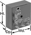
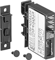 | 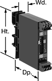 |  | 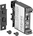 |
Relays with 1 Circuit Controlled, DIP Switches, and Quick-Disconnect Terminals | Relays with 1 Circuit Controlled, DIP Switches, and Screw Terminals | Relays with 1 Circuit Controlled, Knob, and Quick-Disconnect Terminals | Relays with 1 Circuit Controlled, Knob, and Screw Terminals |
Timing Range | |||||||||||||||||||||||||||||||||||||||||||||||||||||||||||||||||||||||||||||||||||||||||||||||||||
|---|---|---|---|---|---|---|---|---|---|---|---|---|---|---|---|---|---|---|---|---|---|---|---|---|---|---|---|---|---|---|---|---|---|---|---|---|---|---|---|---|---|---|---|---|---|---|---|---|---|---|---|---|---|---|---|---|---|---|---|---|---|---|---|---|---|---|---|---|---|---|---|---|---|---|---|---|---|---|---|---|---|---|---|---|---|---|---|---|---|---|---|---|---|---|---|---|---|---|---|
No. of Terminals | Input Voltage | Control Current, mA | Timer Relay Function | No. of | Overall | Switching Current @ Voltage | Max. Switching Voltage, V AC | Ht. | Wd. | Dp. | Wire Connection | Each | |||||||||||||||||||||||||||||||||||||||||||||||||||||||||||||||||||||||||||||||||||||||
Timing-Adjustment DIP Switch | |||||||||||||||||||||||||||||||||||||||||||||||||||||||||||||||||||||||||||||||||||||||||||||||||||
1 Circuit Controlled with 1 Off—SPST-NO | |||||||||||||||||||||||||||||||||||||||||||||||||||||||||||||||||||||||||||||||||||||||||||||||||||
| 4 | 24V AC, 48V AC, 120V AC, 240V AC | 8 | Delayed Start (Delay on Make) Interval Switch on (Single Shot) Delayed Switch Off (Delay on Break) Repeat Cycle | 4 | 0.1 sec. to 63 min. | 0.7 amp @ 240V AC | 240 | 3" | 0.7" | 2.4" | Quick-Disconnect Terminal | 7399K25 | 0000000 | ||||||||||||||||||||||||||||||||||||||||||||||||||||||||||||||||||||||||||||||||||||||
| 4 | 9V DC, 12V DC, 24V DC, 48V DC, 60V DC, 110V DC | 8 | Delayed Start (Delay on Make) Interval Switch on (Single Shot) Delayed Switch Off (Delay on Break) Repeat Cycle | 4 | 0.1 sec. to 63 min. | 0.7 amp @ 240V AC | 240 | 3" | 0.7" | 2.4" | Quick-Disconnect Terminal | 7399K26 | 000000 | ||||||||||||||||||||||||||||||||||||||||||||||||||||||||||||||||||||||||||||||||||||||
| 6 | 9V DC, 12V DC, 24V DC, 48V DC, 60V DC, 110V DC | 8 | Delayed Start (Delay on Make) Interval Switch on (Single Shot) Delayed Switch Off (Delay on Break) Repeat Cycle | 4 | 0.1 sec. to 63 min. | 0.7 amp @ 240V AC | 240 | 3" | 0.7" | 2.4" | Screw Terminal | 7399K28 | 000000 | ||||||||||||||||||||||||||||||||||||||||||||||||||||||||||||||||||||||||||||||||||||||
Timing-Adjustment Knob | |||||||||||||||||||||||||||||||||||||||||||||||||||||||||||||||||||||||||||||||||||||||||||||||||||
1 Circuit Controlled with 1 Off—SPST-NO | |||||||||||||||||||||||||||||||||||||||||||||||||||||||||||||||||||||||||||||||||||||||||||||||||||
| 4 | 24V AC, 48V AC, 120V AC, 240V AC | 8 | Delayed Start (Delay on Make) Interval Switch on (Single Shot) Delayed Switch Off (Delay on Break) Repeat Cycle | 4 | 0.1 sec. to 100 min. | 0.7 amp @ 240V AC | 240 | 3" | 0.7" | 2.4" | Quick-Disconnect Terminal | 7399K21 | 000000 | ||||||||||||||||||||||||||||||||||||||||||||||||||||||||||||||||||||||||||||||||||||||
| 4 | 9V DC, 12V DC, 24V DC, 48V DC, 60V DC, 110V DC | 8 | Delayed Start (Delay on Make) Interval Switch on (Single Shot) Delayed Switch Off (Delay on Break) Repeat Cycle | 4 | 0.1 sec. to 100 min. | 0.7 amp @ 240V AC | 240 | 3" | 0.7" | 2.4" | Quick-Disconnect Terminal | 7399K22 | 000000 | ||||||||||||||||||||||||||||||||||||||||||||||||||||||||||||||||||||||||||||||||||||||
| 6 | 24V AC, 48V AC, 120V AC, 240V AC | 8 | Delayed Start (Delay on Make) Interval Switch on (Single Shot) Delayed Switch Off (Delay on Break) Repeat Cycle | 4 | 0.1 sec. to 100 min. | 0.7 amp @ 240V AC | 240 | 3" | 0.7" | 2.4" | Screw Terminal | 7399K23 | 000000 | ||||||||||||||||||||||||||||||||||||||||||||||||||||||||||||||||||||||||||||||||||||||
| 6 | 9V DC, 12V DC, 24V DC, 48V DC, 60V DC, 110V DC | 8 | Delayed Start (Delay on Make) Interval Switch on (Single Shot) Delayed Switch Off (Delay on Break) Repeat Cycle | 4 | 0.1 sec. to 100 min. | 0.7 amp @ 240V AC | 240 | 3" | 0.7" | 2.4" | Screw Terminal | 7399K24 | 000000 | ||||||||||||||||||||||||||||||||||||||||||||||||||||||||||||||||||||||||||||||||||||||
Vibration-Actuated Hour Meters
 |  |
Adhesive Back Style D | Magnetic Back Style E |
Record the running time of machines and vehicles that vibrate while operating. These meters are battery powered, so they don’t require any special wiring or external power source.
Style D—Style D meters let you switch between two sensitivity levels to prevent inaccurate counts during transport.
Not Resettable—Non-resettable counters prevent tampering and accidental loss of data.
IP67 Enclosure Rating and IP68 Enclosure Rating—IP67 or IP68 rated, these meters seal out water from temporary submersion.
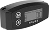
Preventative Maintenance and Inspection Indicators
 |  |
Timing Cycle, day | Resettable | Dia. | Ht. | Thk. | Batteries Included | Mounting Fasteners Included | Enclosure Rating | Each | |||||||||||||||||||||||||||||||||||||||||||||||||||||||||||||||||||||||||||||||||||||||||||
|---|---|---|---|---|---|---|---|---|---|---|---|---|---|---|---|---|---|---|---|---|---|---|---|---|---|---|---|---|---|---|---|---|---|---|---|---|---|---|---|---|---|---|---|---|---|---|---|---|---|---|---|---|---|---|---|---|---|---|---|---|---|---|---|---|---|---|---|---|---|---|---|---|---|---|---|---|---|---|---|---|---|---|---|---|---|---|---|---|---|---|---|---|---|---|---|---|---|---|---|
Screw On, Hanging Mount, Tie On | |||||||||||||||||||||||||||||||||||||||||||||||||||||||||||||||||||||||||||||||||||||||||||||||||||
| 7 | Yes | 2 1/2" | 3 5/8" | 7/8" | Yes | Yes | IP65 | 3545N1 | 000000 | ||||||||||||||||||||||||||||||||||||||||||||||||||||||||||||||||||||||||||||||||||||||||||
| 30 | Yes | 2 1/2" | 3 5/8" | 7/8" | Yes | Yes | IP65 | 3545N2 | 00000 | ||||||||||||||||||||||||||||||||||||||||||||||||||||||||||||||||||||||||||||||||||||||||||
| 180 | Yes | 2 1/2" | 3 5/8" | 7/8" | Yes | Yes | IP65 | 3545N4 | 00000 | ||||||||||||||||||||||||||||||||||||||||||||||||||||||||||||||||||||||||||||||||||||||||||
| 365 | Yes | 2 1/2" | 3 5/8" | 7/8" | Yes | Yes | IP65 | 3545N5 | 00000 | ||||||||||||||||||||||||||||||||||||||||||||||||||||||||||||||||||||||||||||||||||||||||||
Tachometers/Hour Meters for Gas Powered Engines
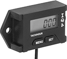 |
Continuously measure the speed and running time of your engine to monitor its performance and detect mechanical issues early. These meters can be programmed based on engine run time to light up for maintenance reminders, such as oil changes, filter replacements, and inspections. Wrap the signal wire four to five times around your spark plug to secure it in place. They’re battery powered, so they will start showing readings as soon as you turn on the engine. It adjusts to nine different engine types for accurate readings.
IP67 Enclosure Rating—They’re rated IP67, so they won’t get damaged from dust and water.
For Panel Cutout | Overall | Mounting | |||||||||||||||||||||||||||||||||||||||||||||||||||||||||||||||||||||||||||||||||||||||||||||||||
|---|---|---|---|---|---|---|---|---|---|---|---|---|---|---|---|---|---|---|---|---|---|---|---|---|---|---|---|---|---|---|---|---|---|---|---|---|---|---|---|---|---|---|---|---|---|---|---|---|---|---|---|---|---|---|---|---|---|---|---|---|---|---|---|---|---|---|---|---|---|---|---|---|---|---|---|---|---|---|---|---|---|---|---|---|---|---|---|---|---|---|---|---|---|---|---|---|---|---|---|
Velocity Measured Range, rpm | Accuracy | Digital Display Type | Resettable | Counting Direction | No. of Digits | Measurement Unit | Ht. | Wd. | Dp. | Ht. | Wd. | Dp. | Batteries Included | Fasteners Included | Screw Size | Features | Enclosure Rating | Each | |||||||||||||||||||||||||||||||||||||||||||||||||||||||||||||||||||||||||||||||||
Adhesive Back | |||||||||||||||||||||||||||||||||||||||||||||||||||||||||||||||||||||||||||||||||||||||||||||||||||
Wraparound Connection | |||||||||||||||||||||||||||||||||||||||||||||||||||||||||||||||||||||||||||||||||||||||||||||||||||
| 0 to 25,000 | ±0.002 | LCD | Yes | Up | 6 | Revolutions per Minute | 1.6" | 2.3" | 0.8" | 1.56" | 3.15" | 0.79" | Yes | No | No. 12 | Battery-Powered Display, Maintenance Reminder, Maximum RPM Reading Recall, Timer | IP67 | 6117N11 | 000000 | ||||||||||||||||||||||||||||||||||||||||||||||||||||||||||||||||||||||||||||||||
Electric-Motor-Actuated Hour Meters
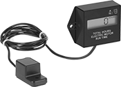 |
With a sensor that’s activated by your electric motor’s magnetic field, these meters show the motor’s running time. To mount the meter sensor to your motor, use the adhesive back.
Not Resettable—Non-resettable counter prevents tampering and accidental loss of data.
Resettable—Resettable counter alerts the user when the count reaches a set point.
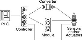
IO Link Connectors
 |
Components Sold Separately |
Create a system of sensors and actuators that you can remotely update, view measurements from, and receive error messages in real time. IO Link systems minimize downtime by locating issues such as cut cables or dirty sensors quickly. They send only digital signals to your PLC, regardless of whether your sensors and actuators send digital or analog signals. Because these systems send digital signals, they’re more reliable and less prone to data error and signal loss than analog signals. It also means you don't have to use expensive shielded cables since they resist EMI.
When retrofitting an existing system, you'll need to make sure your PLC can incorporate IO Link. Check with your PLC manufacturer—most have hardware that allows you to upgrade your PLC to run IO Link.
Note: Sockets may have extra holes on their face that are not used.
Controllers
Surface Mount |
Controllers communicate between your sensors and actuators and your PLC. They are required. Setting memory automatically stores your settings and restores them once your device is back online. This eliminates needing to program a device again when you replace or fix it.
Surface Mount—Surface mount controllers let you mount controllers on equipment such as tanks and conveyors. By mounting them on your equipment, you save space in your control cabinet. They use M12 connectors.
IP66 Enclosure Rating—IP66 rated components withstand washdowns.
IP67 Enclosure Rating—IP67 rated components can be temporarily submerged in water.
IP69K Enclosure Rating—IP69K rated components hold up to high-pressure and high-temperature washdowns.
Enclosure Rating—IP rated components block out dust and withstand some water, so they do not require an enclosure. Ports that are unused must be capped to maintain their rating.
Input | Output | ||||||||||||||||||||||||||||||||||||||||||||||||||||||||||||||||||||||||||||||||||||||||||||||||||
|---|---|---|---|---|---|---|---|---|---|---|---|---|---|---|---|---|---|---|---|---|---|---|---|---|---|---|---|---|---|---|---|---|---|---|---|---|---|---|---|---|---|---|---|---|---|---|---|---|---|---|---|---|---|---|---|---|---|---|---|---|---|---|---|---|---|---|---|---|---|---|---|---|---|---|---|---|---|---|---|---|---|---|---|---|---|---|---|---|---|---|---|---|---|---|---|---|---|---|---|
Communication Protocol | No. of Device Ports | Total No. of M12 Connections | Type | Signal | Voltage, V DC | No. of | Type | Signal | Voltage, V DC | Current, mA | No. of | Operating Voltage, V DC | Certification | Each | |||||||||||||||||||||||||||||||||||||||||||||||||||||||||||||||||||||||||||||||||||||
Surface Mount | |||||||||||||||||||||||||||||||||||||||||||||||||||||||||||||||||||||||||||||||||||||||||||||||||||
IP66, IP67 | |||||||||||||||||||||||||||||||||||||||||||||||||||||||||||||||||||||||||||||||||||||||||||||||||||
| IO Link, Ethernet/IP | 4 | 7 | Digital | PNP | 0 to 30 | 8 | Digital | PNP | 30 | 0.3 amp | 4 | 20 to 30 | UL Listed, C-UL Listed, CE Marked | 7585N13 | 0000000 | ||||||||||||||||||||||||||||||||||||||||||||||||||||||||||||||||||||||||||||||||||||
| IO Link, Ethernet/IP | 8 | 11 | Digital | PNP | 0 to 30 | 16 | Digital | PNP | 30 | 0.3 amp | 8 | 20 to 30 | UL Listed, C-UL Listed, CE Marked | 7585N14 | 000000 | ||||||||||||||||||||||||||||||||||||||||||||||||||||||||||||||||||||||||||||||||||||
| IO Link, Profinet | 4 | 7 | Digital | PNP | 0 to 30 | 8 | Digital | PNP | 30 | 0.3 amp | 4 | 20 to 30 | UL Listed, C-UL Listed, CE Marked | 7585N11 | 000000 | ||||||||||||||||||||||||||||||||||||||||||||||||||||||||||||||||||||||||||||||||||||
| IO Link, Profinet | 8 | 11 | Digital | PNP | 0 to 30 | 16 | Digital | PNP | 30 | 0.3 amp | 8 | 20 to 30 | UL Listed, C-UL Listed, CE Marked | 7585N12 | 000000 | ||||||||||||||||||||||||||||||||||||||||||||||||||||||||||||||||||||||||||||||||||||
IP66, IP67, IP69K | |||||||||||||||||||||||||||||||||||||||||||||||||||||||||||||||||||||||||||||||||||||||||||||||||||
| IO Link, Ethernet/IP | 4 | 7 | Digital | PNP | 0 to 30 | 8 | Digital | PNP | 30 | 0.3 amp | 4 | 20 to 30 | UL Listed, C-UL Listed, CE Marked | 7585N19 | 000000 | ||||||||||||||||||||||||||||||||||||||||||||||||||||||||||||||||||||||||||||||||||||
| IO Link, Ethernet/IP | 8 | 11 | Digital | PNP | 0 to 30 | 16 | Digital | PNP | 30 | 0.3 amp | 8 | 20 to 30 | UL Listed, C-UL Listed, CE Marked | 7585N21 | 000000 | ||||||||||||||||||||||||||||||||||||||||||||||||||||||||||||||||||||||||||||||||||||
| IO Link, Profinet | 4 | 7 | Digital | PNP | 0 to 30 | 8 | Digital | PNP | 30 | 0.3 amp | 4 | 20 to 30 | UL Listed, C-UL Listed, CE Marked | 7585N17 | 000000 | ||||||||||||||||||||||||||||||||||||||||||||||||||||||||||||||||||||||||||||||||||||
| IO Link, Profinet | 8 | 11 | Digital | PNP | 0 to 30 | 16 | Digital | PNP | 30 | 0.3 amp | 8 | 20 to 30 | UL Listed, C-UL Listed, CE Marked | 7585N18 | 000000 | ||||||||||||||||||||||||||||||||||||||||||||||||||||||||||||||||||||||||||||||||||||
 |
For Plugs |
 |
For Sockets |
Expansion Modules
 |
Expansion modules increase the number of inputs and outputs in your IO Link system, so you can add more sensors and actuators to your network. Connect multiple devices to each expansion module using M12 connectors, without needing to wire your devices inside a control cabinet. They transmit signals from multiple devices with a single cord. Expansion modules are optional, but when used, they must connect to a controller. Mount them on your equipment to save space in your control cabinet.
IP65 Enclosure Rating—IP65 rated components can be rinsed.
IP67 Enclosure Rating—IP67 rated components can be temporarily submerged in water.
IP69K Enclosure Rating—IP69K rated components hold up to high-pressure and high-temperature washdowns.
Enclosure Rating—IP rated components block out dust and withstand some water, so they do not require an enclosure. Ports that are unused must be capped to maintain their rating.
Input | Output | ||||||||||||||||||||||||||||||||||||||||||||||||||||||||||||||||||||||||||||||||||||||||||||||||||
|---|---|---|---|---|---|---|---|---|---|---|---|---|---|---|---|---|---|---|---|---|---|---|---|---|---|---|---|---|---|---|---|---|---|---|---|---|---|---|---|---|---|---|---|---|---|---|---|---|---|---|---|---|---|---|---|---|---|---|---|---|---|---|---|---|---|---|---|---|---|---|---|---|---|---|---|---|---|---|---|---|---|---|---|---|---|---|---|---|---|---|---|---|---|---|---|---|---|---|---|
Expansion Module Type | Communication Protocol | No. of Device Ports | Total No. of M12 Connections | Type | Signal | Voltage, V DC | No. of | Type | Signal | Current, mA | No. of | Operating Voltage, V DC | Certification | Each | |||||||||||||||||||||||||||||||||||||||||||||||||||||||||||||||||||||||||||||||||||||
Surface Mount | |||||||||||||||||||||||||||||||||||||||||||||||||||||||||||||||||||||||||||||||||||||||||||||||||||
IP65, IP67 | |||||||||||||||||||||||||||||||||||||||||||||||||||||||||||||||||||||||||||||||||||||||||||||||||||
| Input | IO Link | 6 | 7 | Digital | PNP | 16 to 30 | 12 | — | — | — | — | 18 to 30 | UL Listed, C-UL Listed, CE Marked | 7603N11 | 0000000 | ||||||||||||||||||||||||||||||||||||||||||||||||||||||||||||||||||||||||||||||||||||
| Input | IO Link | 10 | 11 | Digital | PNP | 16 to 30 | 20 | — | — | — | — | 18 to 30 | UL Listed, C-UL Listed, CE Marked | 7603N12 | 000000 | ||||||||||||||||||||||||||||||||||||||||||||||||||||||||||||||||||||||||||||||||||||
| Input, Output | IO Link | 8 | 10 | Digital | PNP | 18 to 30 | 16 | Digital | PNP | 3.6 amp | 16 | 18 to 30 | CE Marked | 7603N15 | 000000 | ||||||||||||||||||||||||||||||||||||||||||||||||||||||||||||||||||||||||||||||||||||
| Output | IO Link | 6 | 8 | — | — | — | — | Digital | PNP | 3.6 amp | 12 | 18 to 30 | UL Listed, C-UL Listed, CE Marked | 7603N13 | 000000 | ||||||||||||||||||||||||||||||||||||||||||||||||||||||||||||||||||||||||||||||||||||
| Output | IO Link | 10 | 12 | — | — | — | — | Digital | PNP | 3.6 amp | 20 | 18 to 30 | UL Listed, C-UL Listed, CE Marked | 7603N14 | 000000 | ||||||||||||||||||||||||||||||||||||||||||||||||||||||||||||||||||||||||||||||||||||
IP65, IP67, IP69K | |||||||||||||||||||||||||||||||||||||||||||||||||||||||||||||||||||||||||||||||||||||||||||||||||||
| Input | IO Link | 6 | 7 | Digital | PNP | 16 to 30 | 12 | — | — | — | — | 18 to 30 | UL Listed, C-UL Listed, CE Marked | 7603N16 | 000000 | ||||||||||||||||||||||||||||||||||||||||||||||||||||||||||||||||||||||||||||||||||||
| Input | IO Link | 10 | 11 | Digital | PNP | 16 to 30 | 20 | — | — | — | — | 18 to 30 | UL Listed, C-UL Listed, CE Marked | 7603N17 | 000000 | ||||||||||||||||||||||||||||||||||||||||||||||||||||||||||||||||||||||||||||||||||||
| Input, Output | IO Link | 8 | 10 | Digital | PNP | 18 to 30 | 16 | Digital | PNP | 3.6 amp | 16 | 18 to 30 | CE Marked | 7603N21 | 000000 | ||||||||||||||||||||||||||||||||||||||||||||||||||||||||||||||||||||||||||||||||||||
| Output | IO Link | 6 | 8 | — | — | — | — | Digital | PNP | 3.6 amp | 12 | 18 to 30 | UL Listed, C-UL Listed, CE Marked | 7603N18 | 000000 | ||||||||||||||||||||||||||||||||||||||||||||||||||||||||||||||||||||||||||||||||||||
| Output | IO Link | 10 | 12 | — | — | — | — | Digital | PNP | 3.6 amp | 20 | 18 to 30 | UL Listed, C-UL Listed, CE Marked | 7603N19 | 000000 | ||||||||||||||||||||||||||||||||||||||||||||||||||||||||||||||||||||||||||||||||||||
|
For Plugs |
|
For Sockets |
