


Filter by

System of Measurement
Maximum Clamping Clearance

Mount Type

Actuation Type

Body Material
DFARS Specialty Metals
Export Control Classification Number (ECCN)
REACH
Air-Powered Hold-Down Toggle Clamps
 |  |
With Open Arm | With Solid Arm |
Arm | When Clamped | Holding Screws | Air Inlet and Outlet | |||||||||||||||||
|---|---|---|---|---|---|---|---|---|---|---|---|---|---|---|---|---|---|---|---|---|
Holding Cap., lb. | Max. Clamping Clearance | Ht. | Lg. | Opening Angle | Overall Lg. | Overall Ht. | No. of | Tip Material | Thread Size | Max. Air Inlet Pressure, psi | Pipe Size | Thread Size | Thread Type | Gender | Temp. Range, ° F | Body Material | Each | |||
With Open Arm | ||||||||||||||||||||
| 100 | 3/8" | 3/4" | 1 1/8" | 95° | 5 5/8" | 1 5/8" | 2 | Steel, Rubber | M5 | 40 | — | M5 | Metric | Female | -10 to 165 | Steel | 5174A35 | 0000000 | ||
| 200 | 5/8" | 1 1/8" | 1 3/4" | 100° | 7 3/4" | 2 5/8" | 2 | Steel, Rubber | M6 | 30 | 1/8 | — | NPT | Female | -10 to 165 | Steel | 5129A21 | 000000 | ||
| 375 | 29/32" | 1 3/8" | 2 1/2" | 100° | 9 3/8" | 3" | 2 | Steel, Rubber | 5/16"-18 | 45 | 1/8 | — | NPT | Female | -10 to 165 | Steel | 5129A22 | 000000 | ||
| 600 | 1 7/32" | 1 7/8" | 3 5/8" | 95° | 11 3/4" | 3 7/8" | 2 | Steel, Rubber | 3/8"-16 | 50 | 1/8 | — | NPT | Female | -10 to 165 | Steel | 5129A23 | 000000 | ||
| 1,000 | 1 15/32" | 2 1/4" | 4 7/8" | 90° | 15 1/4" | 4 1/2" | 2 | Steel, Rubber | 1/2"-13 | 75 | 1/4 | — | NPT | Female | -10 to 165 | Steel | 5129A24 | 000000 | ||
With Solid Arm | ||||||||||||||||||||
| 4,000 | 3 7/8" | 3 7/8" | 4 13/16" | 95° | 17 1/2" | 7 1/8" | — | — | — | 145 | 1/4 | — | NPT | Female | -14 to 194 | Steel | 5129A25 | 000000 | ||
Air-Powered Push Toggle Clamps
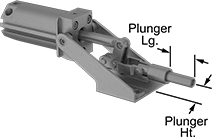 |
Use for repetitive clamping and in production environments. These clamps secure when the plunger is fully extended to hold a workpiece from the side. Air from one inlet port engages the clamp, and air from the other inlet port disengages it. Clamps maintain the full-rated holding capacity even with a loss of air pressure. They have a threaded plunger to accommodate threaded holding screws and other threaded fixtures (not included). Fittings (not included) are required to connect the clamp's ports to a control valve and an air line.
Plunger | When Clamped | Air Inlet and Outlet | |||||||||||||||||
|---|---|---|---|---|---|---|---|---|---|---|---|---|---|---|---|---|---|---|---|
Holding Cap., lb. | Lg. | Ht. | Travel | Shape | Dia. | Thread Location | Thread Size | Thread Lg. | Overall Ht. | Overall Lg. | Max. Air Inlet Pressure, psi | Pipe Size | Thread Type | Gender | Temp. Range, ° F | Each | |||
Push Only—Steel | |||||||||||||||||||
| 600 | 1 1/4" | 1 1/8" | 3/4" | Round | 7/16" | Internal | 5/16"-18 | 1" | 3" | 9 7/8" | 60 | 1/8 | NPT | Female | -10 to 165 | 5137A51 | 0000000 | ||
| 2,500 | 2" | 1 1/8" | 1 1/4" | Round | 5/8" | Internal | 3/8"-16 | 1 1/4" | 3 5/8" | 13 1/2" | 145 | 1/8 | NPT | Female | -10 to 165 | 5137A52 | 000000 | ||
| 16,000 | 3 3/8" | 2 5/8" | 2" | Round | 1" | Internal | 5/8"-11 | 2" | 7 1/4" | 20 5/8" | 145 | 1/4 | NPT | Female | -10 to 165 | 5137A53 | 000000 | ||
Long-Life Dual-Mount Air-Powered Hold-Down Toggle Clamps
 |
These clamps have double the service life of other air-powered toggle clamps. Use for repetitive clamping and in production environments. They have two sets of holes for mounting on the bottom or side. Air from one inlet port engages the clamp, and air from the other inlet port disengages it. Clamps maintain the full-rated holding capacity even with a loss of air pressure. Capacity decreases by as much as 65% when mounting at the end of the arm. Fittings (not included) are required to connect the clamp’s ports to a control valve and an air line.
Arm | When Clamped | Air Inlet and Outlet | ||||||||||||||
|---|---|---|---|---|---|---|---|---|---|---|---|---|---|---|---|---|
Holding Cap., lb. | Max. Clamping Clearance | Ht. | Lg. | Opening Angle | Overall Lg. | Overall Ht. | Max. Air Inlet Pressure, psi | Thread Size | Thread Type | Gender | Temp. Range, ° F | Body Material | Each | |||
With Solid Arm | ||||||||||||||||
| 220 | 3/16" | 3/16" | 1 9/16" | 120° | 2 1/2" | 4 1/16" | 87 | M5 | Metric | Male | -14 to 194 | 6061 Aluminum | 2489N1 | 0000000 | ||
| 530 | 1/4" | 1/4" | 2" | 120° | 3" | 4 11/16" | 87 | M5 | Metric | Male | -14 to 194 | 6061 Aluminum | 2489N2 | 000000 | ||
| 885 | 3/8" | 3/8" | 2 1/8" | 120° | 3 1/2" | 5 15/16" | 87 | M5 | Metric | Male | -14 to 194 | 6061 Aluminum | 2489N3 | 000000 | ||
Dual-Mount Air-Powered Hold-Down Toggle Clamps
 |
Two sets of holes allow mounting on the bottom or side. Use these clamps for repetitive clamping and in production environments. Air from one inlet port engages the clamp, and air from the other inlet port disengages it. Clamps maintain the full-rated holding capacity even with a loss of air pressure. They have an open arm, so you can move the holding screw to any position along the arm. To achieve maximum holding capacity, position the screw closest to the base. Capacity decreases by as much as 65% when the screw is positioned at the end of the arm. Fittings (not included) are required to connect the clamp’s ports to a control valve and an air line.
Arm | When Clamped | Holding Screws | Air Inlet and Outlet | ||||||||||||||||
|---|---|---|---|---|---|---|---|---|---|---|---|---|---|---|---|---|---|---|---|
Holding Cap., lb. | Max. Clamping Clearance | Ht. | Lg. | Opening Angle | Overall Lg. | Overall Ht. | No. of | Tip Material | Thread Size | Max. Air Inlet Pressure, psi | Pipe Size | Thread Type | Gender | Temp. Range, ° F | Body Material | Each | |||
With Open Arm | |||||||||||||||||||
| 350 | 1 5/8" | 2 11/16" | 2 3/8" | 95° | 6 1/4" | 7 1/2" | 2 | Steel, Rubber | 5/16"-18 | 145 | 1/8 | NPT | Female | -14 to 194 | Steel | 2510N11 | 0000000 | ||
| 600 | 2 5/8" | 3 7/8" | 3 1/4" | 85° | 8 5/8" | 9" | 2 | Steel, Rubber | 3/8"-16 | 145 | 1/8 | NPT | Female | -14 to 194 | Steel | 2510N12 | 000000 | ||
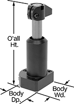
Hydraulic Hold-Down Fixture Clamps
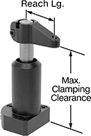 |  | 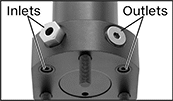 |
Clamping Arm Shown in Clamping Position (Sold Separately) | Clamping Arm Shown in Open Position (Sold Separately) | Hydraulic Ports |
Clamps | Arms | Machinable Arms | |||||||||||||||||||||||
|---|---|---|---|---|---|---|---|---|---|---|---|---|---|---|---|---|---|---|---|---|---|---|---|---|---|
Body | Female Inlet and Outlet | Mounting Holes | |||||||||||||||||||||||
Max. Clamping Clearance | Vert. Travel During Rotation | Max. Clamping Stroke | Overall Ht. | Wd. | Dp. | Thread Type | Thread Size | Max. Clamping Force, lbf | Mounting Fasteners Included | No. of | Thread Size | Dp. | Location | Material | Each | Lg. | Reach Lg. | Each | Lg. | Each | |||||
Double Acting | |||||||||||||||||||||||||
90° Clockwise Rotation | |||||||||||||||||||||||||
| 4 9/16" | 1/2" | 3/8" | 5 5/16" | 2 1/4" | 2 1/8" | UN/UNF (SAE Straight) | 7/16"-20 | 1,250 | Yes | 3 | 1/4"-28 | 5/8" | Lower Flange | Steel | 9964N104 | 0000000 | 2 5/8" | 1 9/16" | 9964N114 | 000000 | 5 13/16" | 9964N117 | 0000000 | ||
| 5 9/16" | 19/32" | 1/2" | 6 3/4" | 2 7/8" | 2 5/8" | UN/UNF (SAE Straight) | 7/16"-20 | 2,600 | Yes | 3 | 5/16"-24 | 13/16" | Lower Flange | Steel | 9964N105 | 000000 | 3 3/8" | 2" | 9964N115 | 000000 | 7 1/16" | 9964N118 | 000000 | ||
| 6 3/16" | 21/32" | 5/8" | 7 3/4" | 3 1/2" | 3 15/16" | UN/UNF (SAE Straight) | 7/16"-20 | 7,600 | Yes | 4 | 3/8"-24 | 3/4" | Lower Flange | Steel | 9964N106 | 00000000 | 4 3/4" | 2 11/16" | 9964N116 | 000000 | 8 1/2" | 9964N119 | 000000 | ||
90° Counterclockwise Rotation | |||||||||||||||||||||||||
| 4 9/16" | 1/2" | 3/8" | 5 5/16" | 2 1/4" | 2 1/8" | UN/UNF (SAE Straight) | 7/16"-20 | 1,250 | Yes | 3 | 1/4"-28 | 5/8" | Lower Flange | Steel | 9964N111 | 000000 | 2 5/8" | 1 9/16" | 9964N114 | 00000 | 5 13/16" | 9964N117 | 000000 | ||
| 5 9/16" | 19/32" | 1/2" | 6 3/4" | 2 7/8" | 2 5/8" | UN/UNF (SAE Straight) | 7/16"-20 | 2,600 | Yes | 3 | 5/16"-24 | 13/16" | Lower Flange | Steel | 9964N112 | 000000 | 3 3/8" | 2" | 9964N115 | 000000 | 7 1/16" | 9964N118 | 000000 | ||
| 6 3/16" | 21/32" | 5/8" | 7 3/4" | 3 1/2" | 3 15/16" | UN/UNF (SAE Straight) | 7/16"-20 | 7,600 | Yes | 4 | 3/8"-24 | 3/4" | Lower Flange | Steel | 9964N113 | 00000000 | 4 3/4" | 2 11/16" | 9964N116 | 000000 | 8 1/2" | 9964N119 | 000000 | ||
