


Filter by
Shaft Diameter
Maximum Torque
OD
Torque
Drive Type
Construction
Engagement Type
Torque Limiter Type


Overall Length
Export Control Classification Number (ECCN)
For Shaft Misalignment Type
DFARS Specialty Metals
Length
Noncontact Magnetic Torque Limiters
Through Shaft
 |
Torque, in·lbf | Max. Rotation Speed, rpm | OD | Overall Lg. | Drive Direction | Shaft Mount Type | Mounting Hole Thread Size | For Shaft Dia. | Each | |||
|---|---|---|---|---|---|---|---|---|---|---|---|
For Round Shafts | |||||||||||
| 1 to 25 | 250 | 4 11/16" | 3 1/8" | Clockwise and Counterclockwise | Set Screw | M5 × 0.8 mm | 3/4" | 7220K6 | 0000000 | ||
| 2 to 50 | 200 | 5 1/4" | 3 1/8" | Clockwise and Counterclockwise | Set Screw | M5 × 0.8 mm | 3/4" | 7220K7 | 000000 | ||
| 3 to 70 | 200 | 6 5/16" | 4 1/8" | Clockwise and Counterclockwise | Set Screw | 1/4"-20 | 3/4" | 7220K8 | 00000000 | ||
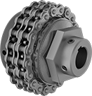
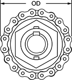
Chain and Belt Torque Limiters
 |  |  |
Torque Limiter Shown with Sprocket | Replacement Friction Lining |
Prevent damage from overloading. When overloaded, these limiters cause your sprocket or pulley to slip. Once the overload is removed, the limiters automatically reset. Set the torque within the range listed. Friction lining is between the hub and pressure plate.
Double Spring—Double-spring limiters have a second spring for handling nearly twice the torque of single-spring limiters.
Sprockets—Sprockets are designed specifically to fit their corresponding limiters. These hubless sprockets are not interchangeable.
Torque Limiters | Sprockets | Replacement Friction Lining | ||||||||||||||||
|---|---|---|---|---|---|---|---|---|---|---|---|---|---|---|---|---|---|---|
Keyway | Torque, ft·lbf | |||||||||||||||||
For Shaft Dia. | OD | Overall Wd. | Wd. | Dp. | For Max. Sprocket or Pulley Wd. | Friction Lining Thk. | Min. | Max. | Hub Material | Each | Choose a Roller Chain Trade Number | Each | Each | |||||
Single Spring | ||||||||||||||||||
| 3/4" | 2 1/4" | 2" | 3/16" | 3/32" | 1/2" | 1/8" | 5 | 35 | Steel | 6524K21 | 0000000 | 35, 40, 41, 50 | 6525K11 | 000000 | 6525K62 | 000000 | ||
| 3/4" | 2 1/2" | 1 3/4" | 3/16" | 3/32" | 11/32" | 1/8" | 25 | 60 | Steel | 6524K123 | 00000 | 35, 40, 41, 50 | 6525K12 | 00000 | 6525K64 | 0000 | ||
| 3/4" | 3 3/8" | 2 1/8" | 3/16" | 3/32" | 1/2" | 1/8" | 11 | 100 | Steel | 6524K28 | 000000 | 35, 40, 41, 50 | 6525K13 | 00000 | 6525K63 | 00000 | ||
| 3/4" | 3 1/2" | 2 3/16" | 3/16" | 3/32" | 1/2" | 1/8" | 50 | 120 | Steel | 6524K141 | 000000 | 35, 40, 41, 50, 60 | 6525K14 | 00000 | 6525K65 | 00000 | ||
| 3/4" | 4 1/2" | 2 7/8" | 3/16" | 3/32" | 7/8" | 1/8" | 18 | 190 | Steel | 6524K321 | 000000 | 35, 40, 41, 50, 60, 80, 100 | 6525K32 | 00000 | 6525K72 | 00000 | ||
Double Spring | ||||||||||||||||||
| 3/4" | 2 1/4" | 2" | 3/16" | 3/32" | 15/32" | 1/8" | 7 | 50 | Steel | 6524K25 | 000000 | 35, 40, 41, 50 | 6525K11 | 00000 | 6525K62 | 00000 | ||
| 3/4" | 2 1/2" | 1 3/4" | 3/16" | 3/32" | 11/32" | 1/8" | 30 | 95 | Steel | 6524K423 | 000000 | 35, 40, 41, 50 | 6525K12 | 00000 | 6525K64 | 0000 | ||
| 3/4" | 3 3/8" | 2 1/8" | 3/16" | 3/32" | 7/16" | 1/8" | 13 | 175 | Steel | 6524K34 | 000000 | 35, 40, 41, 50 | 6525K13 | 00000 | 6525K63 | 00000 | ||
| 3/4" | 3 1/2" | 2 3/16" | 3/16" | 3/32" | 1/2" | 1/8" | 60 | 190 | Steel | 6524K441 | 000000 | 35, 40, 41, 50, 60 | 6525K14 | 00000 | 6525K65 | 00000 | ||
| 3/4" | 4 1/2" | 2 7/8" | 3/16" | 3/32" | 13/16" | 1/8" | 20 | 285 | Steel | 6524K381 | 000000 | 35, 40, 41, 50, 60, 80, 100 | 6525K32 | 00000 | 6525K72 | 00000 | ||


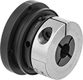
Precision Overload-Protection Spring-Loaded Torque Limiters
Shaft-to-Shaft
 |
Shaft-to-Shaft Torque Limiter, Spider, and Hub Shown Assembled |
 |  |
Hubs | |
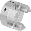 | |
Hubs |
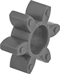
Shaft-to-shaft torque limiters also act as a flexible shaft coupling, so they compensate for angular and parallel misalignment as they regulate torque transmission between shafts. This reduces vibration and protects components from wear. For a complete unit, you’ll need a torque limiter, a hub, and a spider (all sold separately).
Torque Limiters | Hubs | Spiders | |||||||||||||||||||||
|---|---|---|---|---|---|---|---|---|---|---|---|---|---|---|---|---|---|---|---|---|---|---|---|
Keyway | Misalignment Capability | ||||||||||||||||||||||
For Shaft Dia. | Torque, in·lbf | OD | Overall Lg. | Wd. | Dp. | Material | Drive Direction | Shaft Mount Type | Re-Engagement Position | Features | Each | Choose a Shaft Diameter | Each | Max. Rotation Speed, rpm | Parallel | Angular | Temp. Range, ° F | Each | |||||
For Keyed Shafts | |||||||||||||||||||||||
| 3/4" | 90 to 220 | 2 9/16" | 3 3/8" | 3/16" | 3/32" | Steel | Clockwise and Counterclockwise | Clamp On | Single | Sensor Ring, Zero Backlash | 4404N17 | 0000000 | 1/2", 5/8", 3/4" | 4404N27 | 000000 | 9,000 | 0.011" | 1° | 0 to 180 | 9939T14 | 000000 | ||
| 3/4" | 225 to 705 | 2 7/8" | 3 13/16" | 3/16" | 3/32" | Steel | Clockwise and Counterclockwise | Clamp On | Single | Sensor Ring, Zero Backlash | 4404N19 | 000000 | 1/2", 5/8", 3/4", 1", 1 1/4" | 4404N28 | 000000 | 8,000 | 0.011" | 1° | 0 to 180 | 9939T17 | 00000 | ||
Through Shaft
 |
Through-shaft torque limiters regulate torque transmission between an input shaft and a mounted component, such as a pulley, sprocket, or gear.
Keyway | |||||||||||||||
|---|---|---|---|---|---|---|---|---|---|---|---|---|---|---|---|
For Shaft Dia. | Torque, in·lbf | Max. Rotation Speed, rpm | OD | Overall Lg. | Wd. | Dp. | Material | Drive Direction | Shaft Mount Type | Re-Engagement Position | Features | Each | |||
For Keyed Shafts | |||||||||||||||
| 3/4" | 90 to 265 | 6,000 | 2 9/16" | 2" | 3/16" | 3/32" | Steel | Clockwise and Counterclockwise | Clamp On | Single | Sensor Ring, Zero Backlash | 4404N38 | 0000000 | ||
| 3/4" | 225 to 705 | 6,000 | 2 7/8" | 2 1/8" | 3/16" | 3/32" | Steel | Clockwise and Counterclockwise | Clamp On | Single | Sensor Ring, Zero Backlash | 4404N39 | 000000 | ||
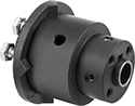
Overload-Protection Spring-Loaded Torque Limiters
 |
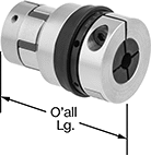
Protect your machinery if there is a jam, emergency stop, or other overload by cutting off torque between shafts when a maximum torque is reached. These torque limiters automatically resume transmitting torque once it drops below the set maximum. They should not be used in applications that frequently exceed the maximum torque. Since they come factory-set to a maximum torque, there’s no adjustment required and no risk of unintended changes to the torque setting.
They act as a flexible shaft coupling, so they reduce vibration and protect components from wear by compensating for angular and parallel misalignment. Fasten to your shafts by tightening the set screws, which bite into each shaft to hold it.
Misalignment Capability | |||||||||||||||
|---|---|---|---|---|---|---|---|---|---|---|---|---|---|---|---|
For Shaft Dia. | For Shaft Type | Max. Rotation Speed, rpm | Parallel | Angular | OD | Overall Lg. | Keyway Wd. × Keyway Dp. | Material | Center Material | Drive Direction | Re-Engagement Position | Choose a Maximum Torque, in·lbf | Each | ||
| 3/4" | Keyed | 1,800 | 0.031" | 6° | 3 1/2" | 3" | 3/16" × 3/32" | 6061 Aluminum | Steel | Clockwise and Counterclockwise | Multiple | 25, 50, 75, 100, 125 | 6609K13 | 0000000 | |
 |  |
Torque Limiter with Sensor Ring Installed |
Material | OD | Thk. | Each | ||
|---|---|---|---|---|---|
| Steel | 3 1/2" | 0.06" | 6609K1 | 000000 |
High-Torque Friction Torque Limiters
Shaft-to-Shaft
 |  |
Single Spring—Single-spring torque limiters let you make finer torque adjustments than double-spring torque limiters but can only withstand half as much torque.
Double Spring—Double-spring torque limiters handle twice as much torque as single-spring torque limiters but are not the best for making precise adjustments at low torques.
Misalignment Capability | Roller Chain | |||||||||||||||
|---|---|---|---|---|---|---|---|---|---|---|---|---|---|---|---|---|
For Shaft Dia. | For Shaft Type | Torque, ft·lbf | Max. Rotation Speed, rpm | Parallel | Angular | OD | Overall Lg. | Keyway Wd. × Keyway Dp. | Drive Direction | Shaft Mount Type | Standard | Trade No. | Each | |||
Single Spring | ||||||||||||||||
| 1/2" × 3/4" | Round × Keyed | 0 to 25 | 1,800 | 0.01" | 3° | 2 3/4" | 2 1/4" | 3/16" × 3/32" | Clockwise and Counterclockwise | Set Screw | ANSI | 35-2 | 4782N115 | 0000000 | ||
| 5/8" × 3/4" | Keyed × Keyed | 0 to 25 | 1,800 | 0.01" | 3° | 2 3/4" | 2 1/4" | 3/16" × 3/32" 3/16" × 3/32" | Clockwise and Counterclockwise | Set Screw | ANSI | 35-2 | 4782N119 | 000000 | ||
| 3/4" × 3/4" | Keyed × Keyed | 0 to 25 | 1,800 | 0.01" | 3° | 2 3/4" | 2 1/4" | 3/16" × 3/32" 3/16" × 3/32" | Clockwise and Counterclockwise | Set Screw | ANSI | 35-2 | 4782N122 | 000000 | ||
Double Spring | ||||||||||||||||
| 1/2" × 3/4" | Round × Keyed | 0 to 50 | 1,800 | 0.01" | 3° | 2 3/4" | 2 1/4" | 3/16" × 3/32" | Clockwise and Counterclockwise | Set Screw | ANSI | 35-2 | 4782N116 | 000000 | ||
| 5/8" × 3/4" | Keyed × Keyed | 0 to 50 | 1,800 | 0.01" | 3° | 2 3/4" | 2 1/4" | 3/16" × 3/32" 3/16" × 3/32" | Clockwise and Counterclockwise | Set Screw | ANSI | 35-2 | 4782N121 | 000000 | ||
| 3/4" × 3/4" | Keyed × Keyed | 0 to 50 | 1,800 | 0.01" | 3° | 2 3/4" | 2 1/4" | 3/16" × 3/32" 3/16" × 3/32" | Clockwise and Counterclockwise | Set Screw | ANSI | 35-2 | 4782N123 | 000000 | ||
Corrosion-Resistant Overload-Protection Spring-Loaded Torque Limiters
 |
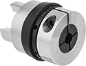
Prevent corrosion from interfering with these torque limiters’ ability to protect your machinery if there’s a jam, emergency stop, or other overload. Made of nylon, they won’t rust or corrode from moisture, salt, and oil. They cut off torque when they reach the set maximum torque and automatically resume transmitting torque once it drops below the set maximum. They should not be used in applications that frequently exceed the set torque. You can adjust the set torque by tightening the hex head screw on the housing.
To help you detect an overload, these torque limiters have a sensor ring that moves out of place when these limiters cut off torque. Use a sensor (not included) to trigger an alarm or a shutdown when the ring moves.
Fasten them to your shaft by tightening the set screws, which bite into the shaft to hold it.
Shaft-to-Shaft
Misalignment Capability | Keyway | |||||||||||||||||
|---|---|---|---|---|---|---|---|---|---|---|---|---|---|---|---|---|---|---|
For Shaft Dia. | Torque, in·lbf | Max. Rotation Speed, rpm | Parallel | Angular | OD | Overall Lg. | Wd. | Dp. | No. of Springs | Material | Drive Direction | Shaft Mount Type | Re-Engagement Position | Features | Each | |||
For Keyed Shafts | ||||||||||||||||||
| 3/4" | 40 to 150 | 1,800 | 0.01" | 1° | 4 1/32" | 3 7/16" | 3/16" | 3/32" | 6 | Nylon | Clockwise and Counterclockwise | Set Screw | Multiple | Sensor Ring | 4410N106 | 0000000 | ||
Through Shaft
Keyway | ||||||||||||||||
|---|---|---|---|---|---|---|---|---|---|---|---|---|---|---|---|---|
For Shaft Dia. | Torque, in·lbf | Max. Rotation Speed, rpm | OD | Overall Lg. | Wd. | Dp. | No. of Springs | Material | Drive Direction | Shaft Mount Type | Re-Engagement Position | Features | Each | |||
For Keyed Shafts | ||||||||||||||||
| 3/4" | 40 to 150 | 1,800 | 4 1/32" | 3 7/16" | 3/16" | 3/32" | 6 | Nylon | Clockwise and Counterclockwise | Set Screw | Multiple | Sensor Ring | 4410N114 | 0000000 | ||
Flexible-Shaft Shear Couplings
 |
To protect power-transmission components from damage, these couplings will shear or tear in overtorque conditions (approximately 10-20 times the maximum rated torque) to sever connections between shafts. They have a flexible center that not only compensates for misalignment, but also dampens vibration and shock loads. Couplings have no metal-on-metal contact, reducing noise and eliminating the need for lubrication. Fasten to your shaft by tightening the set screws, which bite into the shaft to hold it.
Misalignment Capability | |||||||||||||
|---|---|---|---|---|---|---|---|---|---|---|---|---|---|
For Shaft Diameter | Max. Torque, in·lbf | Max. Rotation Speed, rpm | Parallel | Angular | OD | Overall Lg. | Material | Center Material | Temp. Range, ° F | Torque-Limiting Direction | Each | ||
| 1/2" × 3/4" | 20 | 10,000 | 0.031" | 2° | 1 5/8" | 2 1/2" | Steel | Neoprene | -30 to 212 | Clockwise and Counterclockwise | 6410K63 | 0000000 | |
| 1/2" × 3/4" | 40 | 10,000 | 0.031" | 2° | 2" | 2 7/8" | Steel | Neoprene | -30 to 212 | Clockwise and Counterclockwise | 6410K65 | 000000 | |
One-Way Clutches
Roller Engagement—Keyed Hub
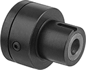 |
Roller clutches are best for low- to medium-torque transfer in overrunning and indexing applications.
Clutches with a keyed hub let you slip on your component.
Through Shaft—Through-shaft clutches regulate torque transmission between an input shaft and a mounted component.
Slip-Fit Shaft Mount—Clutches that mount to shafts with a slip fit must be secured with a shaft collar or in some other way that prevents them from moving along the length of your shaft.
Shaft | Hub | Clockwise Drive | |||||||||||||
|---|---|---|---|---|---|---|---|---|---|---|---|---|---|---|---|
For Shaft Dia. | For Shaft Type | Max. Torque, ft·lbf | Max. Rotation Speed, rpm | OD | Overall Lg. | Material | Keyway Wd. × Keyway Dp. | Mount Type | Dia. | Lg. | Keyway Wd. × Keyway Dp. | Each | |||
Through Shaft | |||||||||||||||
| 3/4" | Keyed | 100 | 1,000 | 3 5/8" | 3 11/32" | Steel | 3/16" × 3/32" | Slip Fit | 2 1/4" | 1 1/2" | 3/8" × 3/16" | 4550N15 | 0000000 | ||
Sprag Engagement—Keyed Hub
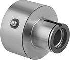 |
Sprag clutches handle higher torque than roller clutches because they have more contact points. This makes them best for backstopping applications.
Clutches with a keyed hub let you slip on your component.
Through Shaft—Through-shaft clutches regulate torque transmission between an input shaft and a mounted component.
Set-Screw Shaft Mount—Clutches that mount to shafts with set screws bite into your shaft when tightened to hold it.
Max. Rotation Speed, rpm | Shaft | Hub | Clockwise Drive | Counterclockwise Drive | ||||||||||||||
|---|---|---|---|---|---|---|---|---|---|---|---|---|---|---|---|---|---|---|
For Shaft Dia. | For Shaft Type | Max. Torque, ft·lbf | Inner-Race | Outer-Race | OD | Overall Lg. | Material | Keyway Wd. × Keyway Dp. | Mount Type | Dia. | Lg. | Keyway Wd. × Keyway Dp. | Each | Each | ||||
Through Shaft | ||||||||||||||||||
| 3/4" | Keyed | 300 | 1,950 | 750 | 2.88" | 3.19" | Steel | 3/16" × 3/32" | Set Screw | 1 3/8" | 1 5/16" | 3/16" × 3/32" | 4550N34 | 000000000 | 4550N33 | 000000000 | ||
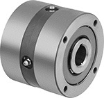
Sprag Engagement—Flush Hub
 | 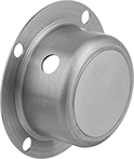 |
Covers |
 | 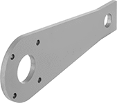 |
Torque Arm Shown Installed | Torque Arms |
Sprag clutches handle higher torque than roller clutches because they have more contact points. This makes them best for backstopping applications.
Clutches with a flush hub have a precision ground outer race, so they can be press fit directly into a component and positioned anywhere along the length of your shaft. They also have mounting holes on their face you can use to secure your component or an anti-rotation device, such as a torque arm, for a different backstopping setup.
Through Shaft—Through-shaft clutches regulate torque transmission between an input shaft and a mounted component.
Slip-Fit Shaft Mount—Clutches that mount to shafts with a slip fit must be secured with a shaft collar or in some other way that prevents them from moving along the length of your shaft.
Covers—Covers protect you from rotating equipment when the clutch is mounted to the end of the shaft.
Torque Arms—Clutch torque arms work as an anchor for clutches in backstopping applications. Mount to the outer race of your clutch and a stationary piece of equipment.
Clutches | Covers | Torque Arms | |||||||||||||||
|---|---|---|---|---|---|---|---|---|---|---|---|---|---|---|---|---|---|
Max. Rotation Speed, rpm | Shaft | Clockwise or Counterclockwise Drive | |||||||||||||||
For Shaft Dia. | For Shaft Type | Max. Torque, ft·lbf | Inner-Race | Outer-Race | OD | Overall Lg. | Material | Keyway Wd. × Keyway Dp. | Mount Type | Each | Each | Each | |||||
Through Shaft | |||||||||||||||||
| 3/4" | Keyed | 300 | 2,800 | 850 | 3 1/2" | 2 3/4" | Steel | 3/16" × 3/32" | Slip Fit | 4550N21 | 000000000 | 4550N201 | 0000000 | 4550N301 | 0000000 | ||
Soft-Start Centrifugal Clutches
Friction Engagement
 |  |  |
Shaft-to-Shaft with Engagement Springs | Shaft-to-Shaft with Support Rollers | Through Shaft with Support Rollers and Pulley |
Shaft-to-Shaft—Shaft-to-shaft clutches also act as a shaft coupling, allowing you to regulate torque transmission between two shafts.
Through Shaft—Through-shaft clutches regulate torque transmission between an input shaft and a mounted component.
Support Rollers—Clutches with support rollers are quieter and last longer than other centrifugal clutches because the contact points are supported by urethane rollers to prevent slipping.
With Pulley—Clutches with a pulley come ready to install a V-belt.
Set-Screw Shaft Mount—Clutches that mount to shafts with set screws bite into your shaft when tightened to hold it.
Misalignment Capability | Clockwise-and-Counterclockwise Drive | ||||||||||||||||
|---|---|---|---|---|---|---|---|---|---|---|---|---|---|---|---|---|---|
For Shaft Dia. | For Shaft Type | Engagement Speed, rpm | Max. Power, hp | Max. Rotation Speed, rpm | Pitch Dia. | For Belt Trade Size | Parallel | Angular | OD | Overall Lg. | Keyway Wd. × Keyway Dp. | Material | Shaft Mount Type | Each | |||
Shaft-to-Shaft with Engagement Springs | |||||||||||||||||
| 3/4" | Keyed | 830 | 13 | 3,600 | — | — | 0.003" | 0.25° | 4 3/16" | 2 1/2" | 3/16" × 3/32" | Steel | Set Screw | 4402N112 | 0000000 | ||
Shaft-to-Shaft with Support Rollers | |||||||||||||||||
| 3/4" | Keyed | 1,100 | 7.5 | 1,750 | — | — | — | — | 3 63/64" | 3 19/64" | 3/16" × 3/32" | Steel | Set Screw | 4402N131 | 000000 | ||
Through Shaft with Support Rollers and Pulley | |||||||||||||||||
| 3/4" | Keyed | 1,100 | 7.5 | 1,750 | 2.8" | 4L, A | — | — | 3 63/64" | 1 7/8" | 3/16" × 3/32" | Steel | Set Screw | 4402N142 | 000000 | ||
| 3/4" | Keyed | 1,100 | 7.5 | 1,750 | 3.3" | 4L, A | — | — | 3 63/64" | 1 7/8" | 3/16" × 3/32" | Steel | Set Screw | 4402N152 | 000000 | ||
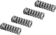
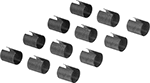 |
Includes | Each | ||
|---|---|---|---|
| Four Green Springs (830 RPM Engagement), Four Red Springs (1200 RPM Engagement), Four Orange Springs (1800 RPM Engagement) | 4402N11 | 000000 |
