


Filter by

Wire Connection

Voltage
Current per Circuit
Length
Performance
Electrical Connection
Height
Certification
Export Control Classification Number (ECCN)
DFARS Specialty Metals


Touch-Safe Terminal Blocks
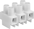 |  | 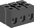 |
Style A | Style B | Style C |
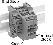
These terminal blocks protect you from shocks and prevent short circuits. The terminals are recessed in the block, so you can't accidentally touch them when installing or adjusting your wire.
Screw-Clamp-Terminal Wire Connection—The clamp flattens the wire to resist pullout and vibration better than screw terminals. For an even stronger and more conductive connection, crimp a terminal or wire ferrule onto the end of the wire.
For DIN 3 Rails—Unlike other surface-mount terminal blocks, these have a notch that snaps onto DIN 3 rail. You can also screw them directly onto your control panel or other surface.
Markers—Label your terminal block connections so you can identify them at a glance. These markers extend from underneath the terminal block.
Terminal Blocks | Markers | ||||||||||||||||||||||||||||||||||||||||||||||||||||||||||||||||||||||||||||||||||||||||||||||||||
|---|---|---|---|---|---|---|---|---|---|---|---|---|---|---|---|---|---|---|---|---|---|---|---|---|---|---|---|---|---|---|---|---|---|---|---|---|---|---|---|---|---|---|---|---|---|---|---|---|---|---|---|---|---|---|---|---|---|---|---|---|---|---|---|---|---|---|---|---|---|---|---|---|---|---|---|---|---|---|---|---|---|---|---|---|---|---|---|---|---|---|---|---|---|---|---|---|---|---|---|
Mounting Holes | |||||||||||||||||||||||||||||||||||||||||||||||||||||||||||||||||||||||||||||||||||||||||||||||||||
Style | No. of Circuits | For Wire Ga. | Wire Connection | Terminal Size | Terminal Ctr.-to-Ctr. | Lg. | Wd. | Ht. | Max. Temp., ° F | Color | For DIN Rail Trade Size | Dia. | No. of | Enclosure Rating | Each | Pkg. Qty. | Pkg. | ||||||||||||||||||||||||||||||||||||||||||||||||||||||||||||||||||||||||||||||||||
600V AC/600V DC—20 amp per Circuit | |||||||||||||||||||||||||||||||||||||||||||||||||||||||||||||||||||||||||||||||||||||||||||||||||||
| A | 2 | 22 to 12 | Screw-Clamp Terminal | M3 | 5/16" | 1/2" | 3/4" | 3/4" | 221 | White | — | 0.12" | 1 | — | 00000000 | 00000 | — | ——— | 0 | ||||||||||||||||||||||||||||||||||||||||||||||||||||||||||||||||||||||||||||||||
| A | 3 | 22 to 12 | Screw-Clamp Terminal | M3 | 5/16" | 7/8" | 3/4" | 3/4" | 221 | White | — | 0.12" | 2 | — | 00000000 | 0000 | — | ——— | 0 | ||||||||||||||||||||||||||||||||||||||||||||||||||||||||||||||||||||||||||||||||
| A | 4 | 22 to 12 | Screw-Clamp Terminal | M3 | 5/16" | 1 3/16" | 3/4" | 3/4" | 221 | White | — | 0.12" | 3 | — | 00000000 | 0000 | — | ——— | 0 | ||||||||||||||||||||||||||||||||||||||||||||||||||||||||||||||||||||||||||||||||
| A | 6 | 22 to 12 | Screw-Clamp Terminal | M3 | 5/16" | 1 13/16" | 3/4" | 3/4" | 221 | White | — | 0.12" | 5 | — | 00000000 | 0000 | — | ——— | 0 | ||||||||||||||||||||||||||||||||||||||||||||||||||||||||||||||||||||||||||||||||
| A | 8 | 22 to 12 | Screw-Clamp Terminal | M3 | 5/16" | 2 7/16" | 3/4" | 3/4" | 221 | White | — | 0.12" | 7 | — | 00000000 | 0000 | — | ——— | 0 | ||||||||||||||||||||||||||||||||||||||||||||||||||||||||||||||||||||||||||||||||
| A | 9 | 22 to 12 | Screw-Clamp Terminal | M3 | 5/16" | 2 3/4" | 3/4" | 3/4" | 221 | White | — | 0.12" | 8 | — | 00000000 | 0000 | — | ——— | 0 | ||||||||||||||||||||||||||||||||||||||||||||||||||||||||||||||||||||||||||||||||
| A | 10 | 22 to 12 | Screw-Clamp Terminal | M3 | 5/16" | 3 1/16" | 3/4" | 3/4" | 221 | White | — | 0.12" | 9 | — | 00000000 | 0000 | — | ——— | 0 | ||||||||||||||||||||||||||||||||||||||||||||||||||||||||||||||||||||||||||||||||
| A | 12 | 22 to 12 | Screw-Clamp Terminal | M3 | 5/16" | 3 11/16" | 3/4" | 3/4" | 221 | White | — | 0.12" | 11 | — | 00000000 | 0000 | — | ——— | 0 | ||||||||||||||||||||||||||||||||||||||||||||||||||||||||||||||||||||||||||||||||
600V AC—30 amp per Circuit | |||||||||||||||||||||||||||||||||||||||||||||||||||||||||||||||||||||||||||||||||||||||||||||||||||
| B | 4 | 18 to 10 | Screw-Clamp Terminal | No. 8 | 9/16" | 2 3/8" | 1 3/16" | 1 3/4" | 220 | Black | 3 | 0.18" | 2 | IP20 | 0000000 | 0000 | 10 | 00000000 | 00000 | ||||||||||||||||||||||||||||||||||||||||||||||||||||||||||||||||||||||||||||||||
| B | 6 | 18 to 10 | Screw-Clamp Terminal | No. 8 | 9/16" | 3 1/2" | 1 3/16" | 1 3/4" | 220 | Black | 3 | 0.18" | 2 | IP20 | 0000000 | 00000 | 10 | 00000000 | 0000 | ||||||||||||||||||||||||||||||||||||||||||||||||||||||||||||||||||||||||||||||||
| B | 12 | 18 to 10 | Screw-Clamp Terminal | No. 8 | 9/16" | 6 7/8" | 1 3/16" | 1 3/4" | 220 | Black | 3 | 0.18" | 2 | IP20 | 0000000 | 00000 | 10 | 00000000 | 0000 | ||||||||||||||||||||||||||||||||||||||||||||||||||||||||||||||||||||||||||||||||
600V AC/600V DC—30 amp per Circuit | |||||||||||||||||||||||||||||||||||||||||||||||||||||||||||||||||||||||||||||||||||||||||||||||||||
| A | 2 | 18 to 10 | Screw-Clamp Terminal | M3 | 3/8" | 11/16" | 3/4" | 13/16" | 221 | White | — | 0.15" | 1 | — | 00000000 | 0000 | — | ——— | 0 | ||||||||||||||||||||||||||||||||||||||||||||||||||||||||||||||||||||||||||||||||
| A | 3 | 18 to 10 | Screw-Clamp Terminal | M3 | 3/8" | 1 1/16" | 3/4" | 13/16" | 221 | White | — | 0.15" | 2 | — | 00000000 | 0000 | — | ——— | 0 | ||||||||||||||||||||||||||||||||||||||||||||||||||||||||||||||||||||||||||||||||
| A | 4 | 18 to 10 | Screw-Clamp Terminal | M3 | 3/8" | 1 7/16" | 3/4" | 13/16" | 221 | White | — | 0.15" | 3 | — | 00000000 | 0000 | — | ——— | 0 | ||||||||||||||||||||||||||||||||||||||||||||||||||||||||||||||||||||||||||||||||
| A | 6 | 18 to 10 | Screw-Clamp Terminal | M3 | 3/8" | 2 1/4" | 3/4" | 13/16" | 221 | White | — | 0.15" | 5 | — | 00000000 | 0000 | — | ——— | 0 | ||||||||||||||||||||||||||||||||||||||||||||||||||||||||||||||||||||||||||||||||
| A | 8 | 18 to 10 | Screw-Clamp Terminal | M3 | 3/8" | 3" | 3/4" | 13/16" | 221 | White | — | 0.15" | 7 | — | 00000000 | 0000 | — | ——— | 0 | ||||||||||||||||||||||||||||||||||||||||||||||||||||||||||||||||||||||||||||||||
| A | 9 | 18 to 10 | Screw-Clamp Terminal | M3 | 3/8" | 3 7/16" | 3/4" | 13/16" | 221 | White | — | 0.15" | 8 | — | 00000000 | 0000 | — | ——— | 0 | ||||||||||||||||||||||||||||||||||||||||||||||||||||||||||||||||||||||||||||||||
| A | 10 | 18 to 10 | Screw-Clamp Terminal | M3 | 3/8" | 3 13/16" | 3/4" | 13/16" | 221 | White | — | 0.15" | 9 | — | 00000000 | 0000 | — | ——— | 0 | ||||||||||||||||||||||||||||||||||||||||||||||||||||||||||||||||||||||||||||||||
| A | 12 | 18 to 10 | Screw-Clamp Terminal | M3 | 3/8" | 4 5/8" | 3/4" | 13/16" | 221 | White | — | 0.15" | 11 | — | 00000000 | 0000 | — | ——— | 0 | ||||||||||||||||||||||||||||||||||||||||||||||||||||||||||||||||||||||||||||||||
600V AC/600V DC—40 amp per Circuit | |||||||||||||||||||||||||||||||||||||||||||||||||||||||||||||||||||||||||||||||||||||||||||||||||||
| A | 2 | 20 to 8 | Screw-Clamp Terminal | M3 | 1/2" | 13/16" | 15/16" | 7/8" | 221 | White | — | 0.17" | 1 | — | 00000000 | 0000 | — | ——— | 0 | ||||||||||||||||||||||||||||||||||||||||||||||||||||||||||||||||||||||||||||||||
| A | 3 | 20 to 8 | Screw-Clamp Terminal | M3 | 1/2" | 1 1/4" | 15/16" | 7/8" | 221 | White | — | 0.17" | 2 | — | 00000000 | 0000 | — | ——— | 0 | ||||||||||||||||||||||||||||||||||||||||||||||||||||||||||||||||||||||||||||||||
| A | 4 | 20 to 8 | Screw-Clamp Terminal | M3 | 1/2" | 1 3/4" | 15/16" | 7/8" | 221 | White | — | 0.17" | 3 | — | 00000000 | 0000 | — | ——— | 0 | ||||||||||||||||||||||||||||||||||||||||||||||||||||||||||||||||||||||||||||||||
| A | 6 | 20 to 8 | Screw-Clamp Terminal | M3 | 1/2" | 2 11/16" | 15/16" | 7/8" | 221 | White | — | 0.17" | 5 | — | 00000000 | 0000 | — | ——— | 0 | ||||||||||||||||||||||||||||||||||||||||||||||||||||||||||||||||||||||||||||||||
| A | 8 | 20 to 8 | Screw-Clamp Terminal | M3 | 1/2" | 3 5/8" | 15/16" | 7/8" | 221 | White | — | 0.17" | 7 | — | 00000000 | 0000 | — | ——— | 0 | ||||||||||||||||||||||||||||||||||||||||||||||||||||||||||||||||||||||||||||||||
| A | 9 | 20 to 10 | Screw-Clamp Terminal | M3 | 1/2" | 4 1/16" | 15/16" | 7/8" | 257 | White | — | 0.17" | 8 | — | 00000000 | 0000 | — | ——— | 0 | ||||||||||||||||||||||||||||||||||||||||||||||||||||||||||||||||||||||||||||||||
| A | 10 | 20 to 8 | Screw-Clamp Terminal | M3 | 1/2" | 4 9/16" | 15/16" | 7/8" | 221 | White | — | 0.17" | 9 | — | 00000000 | 0000 | — | ——— | 0 | ||||||||||||||||||||||||||||||||||||||||||||||||||||||||||||||||||||||||||||||||
| A | 12 | 20 to 8 | Screw-Clamp Terminal | M3 | 1/2" | 5 1/2" | 15/16" | 7/8" | 221 | White | — | 0.17" | 11 | — | 00000000 | 0000 | — | ——— | 0 | ||||||||||||||||||||||||||||||||||||||||||||||||||||||||||||||||||||||||||||||||
600V AC/600V DC—63 amp per Circuit | |||||||||||||||||||||||||||||||||||||||||||||||||||||||||||||||||||||||||||||||||||||||||||||||||||
| A | 2 | 14 to 6 | Screw-Clamp Terminal | M3 | 9/16" | 1" | 1 1/8" | 1 1/16" | 221 | White | — | 0.17" | 1 | — | 00000000 | 0000 | — | ——— | 0 | ||||||||||||||||||||||||||||||||||||||||||||||||||||||||||||||||||||||||||||||||
| A | 3 | 14 to 6 | Screw-Clamp Terminal | M3 | 9/16" | 1 9/16" | 1 1/8" | 1 1/16" | 221 | White | — | 0.17" | 2 | — | 00000000 | 0000 | — | ——— | 0 | ||||||||||||||||||||||||||||||||||||||||||||||||||||||||||||||||||||||||||||||||
| A | 4 | 14 to 6 | Screw-Clamp Terminal | M3 | 9/16" | 2 3/16" | 1 1/8" | 1 1/16" | 221 | White | — | 0.17" | 3 | — | 00000000 | 0000 | — | ——— | 0 | ||||||||||||||||||||||||||||||||||||||||||||||||||||||||||||||||||||||||||||||||
| A | 6 | 14 to 6 | Screw-Clamp Terminal | M3 | 9/16" | 3 3/8" | 1 1/8" | 1 1/16" | 221 | White | — | 0.17" | 5 | — | 00000000 | 0000 | — | ——— | 0 | ||||||||||||||||||||||||||||||||||||||||||||||||||||||||||||||||||||||||||||||||
| A | 8 | 14 to 6 | Screw-Clamp Terminal | M3 | 9/16" | 4 1/2" | 1 1/8" | 1 1/16" | 221 | White | — | 0.17" | 7 | — | 00000000 | 0000 | — | ——— | 0 | ||||||||||||||||||||||||||||||||||||||||||||||||||||||||||||||||||||||||||||||||
| A | 9 | 14 to 6 | Screw-Clamp Terminal | M3 | 9/16" | 5 1/8" | 1 1/8" | 1 1/16" | 221 | White | — | 0.17" | 8 | — | 00000000 | 0000 | — | ——— | 0 | ||||||||||||||||||||||||||||||||||||||||||||||||||||||||||||||||||||||||||||||||
| A | 10 | 14 to 6 | Screw-Clamp Terminal | M3 | 9/16" | 5 11/16" | 1 1/8" | 1 1/16" | 221 | White | — | 0.17" | 9 | — | 00000000 | 00000 | — | ——— | 0 | ||||||||||||||||||||||||||||||||||||||||||||||||||||||||||||||||||||||||||||||||
| A | 12 | 14 to 6 | Screw-Clamp Terminal | M3 | 9/16" | 6 7/8" | 1 1/8" | 1 1/16" | 221 | White | — | 0.17" | 11 | — | 00000000 | 00000 | — | ——— | 0 | ||||||||||||||||||||||||||||||||||||||||||||||||||||||||||||||||||||||||||||||||
600V AC/600V DC—85 amp per Circuit | |||||||||||||||||||||||||||||||||||||||||||||||||||||||||||||||||||||||||||||||||||||||||||||||||||
| C | 2 | 18 to 4 | Screw Terminal | 1/4" | 5/8" | 1 3/16" | 1 1/4" | 1 1/8" | 302 | Black | — | 0.18" | 1 | — | 0000000 | 0000 | — | ——— | 0 | ||||||||||||||||||||||||||||||||||||||||||||||||||||||||||||||||||||||||||||||||
| C | 3 | 18 to 4 | Screw Terminal | 1/4" | 5/8" | 1 3/4" | 1 1/4" | 1 1/8" | 302 | Black | — | 0.18" | 2 | — | 0000000 | 00000 | — | ——— | 0 | ||||||||||||||||||||||||||||||||||||||||||||||||||||||||||||||||||||||||||||||||
| C | 4 | 18 to 4 | Screw Terminal | 1/4" | 5/8" | 2 7/16" | 1 1/4" | 1 1/8" | 302 | Black | — | 0.18" | 3 | — | 0000000 | 00000 | — | ——— | 0 | ||||||||||||||||||||||||||||||||||||||||||||||||||||||||||||||||||||||||||||||||
| C | 5 | 18 to 4 | Screw Terminal | 1/4" | 5/8" | 3" | 1 1/4" | 1 1/8" | 302 | Black | — | 0.18" | 4 | — | 0000000 | 00000 | — | ——— | 0 | ||||||||||||||||||||||||||||||||||||||||||||||||||||||||||||||||||||||||||||||||
| C | 6 | 18 to 4 | Screw Terminal | 1/4" | 5/8" | 3 11/16" | 1 1/4" | 1 1/8" | 302 | Black | — | 0.18" | 5 | — | 0000000 | 00000 | — | ——— | 0 | ||||||||||||||||||||||||||||||||||||||||||||||||||||||||||||||||||||||||||||||||
| C | 8 | 18 to 4 | Screw Terminal | 1/4" | 5/8" | 4 15/16" | 1 1/4" | 1 1/8" | 302 | Black | — | 0.18" | 7 | — | 0000000 | 00000 | — | ——— | 0 | ||||||||||||||||||||||||||||||||||||||||||||||||||||||||||||||||||||||||||||||||
| C | 10 | 18 to 4 | Screw Terminal | 1/4" | 5/8" | 6 3/16" | 1 1/4" | 1 1/8" | 302 | Black | — | 0.18" | 9 | — | 0000000 | 00000 | — | ——— | 0 | ||||||||||||||||||||||||||||||||||||||||||||||||||||||||||||||||||||||||||||||||
| C | 12 | 18 to 4 | Screw Terminal | 1/4" | 5/8" | 7 7/16" | 1 1/4" | 1 1/8" | 302 | Black | — | 0.18" | 11 | — | 0000000 | 00000 | — | ——— | 0 | ||||||||||||||||||||||||||||||||||||||||||||||||||||||||||||||||||||||||||||||||
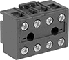
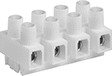
Touch-Safe Plug-and-Socket Terminal Blocks
Mounting Holes | |||||||||||||||||||||||||||||||||||||||||||||||||||||||||||||||||||||||||||||||||||||||||||||||||||
|---|---|---|---|---|---|---|---|---|---|---|---|---|---|---|---|---|---|---|---|---|---|---|---|---|---|---|---|---|---|---|---|---|---|---|---|---|---|---|---|---|---|---|---|---|---|---|---|---|---|---|---|---|---|---|---|---|---|---|---|---|---|---|---|---|---|---|---|---|---|---|---|---|---|---|---|---|---|---|---|---|---|---|---|---|---|---|---|---|---|---|---|---|---|---|---|---|---|---|---|
No. of Circuits | For Wire Ga. | Wire Connection | Terminal Size | Terminal Ctr.-to-Ctr. | Lg. | Wd. | Ht. | Max. Temp., ° F | Color | Dia. | No. of | Each | |||||||||||||||||||||||||||||||||||||||||||||||||||||||||||||||||||||||||||||||||||||||
Plugs | |||||||||||||||||||||||||||||||||||||||||||||||||||||||||||||||||||||||||||||||||||||||||||||||||||
 Plug | |||||||||||||||||||||||||||||||||||||||||||||||||||||||||||||||||||||||||||||||||||||||||||||||||||
600V AC/600V DC—20 amp per Circuit | |||||||||||||||||||||||||||||||||||||||||||||||||||||||||||||||||||||||||||||||||||||||||||||||||||
| 2 | 24 to 10 | Screw Terminal | M3 | 3/8" | 5/8" | 9/16" | 3/4" | 221 | White | 0.12" | 1 | 00000000 | 00000 | ||||||||||||||||||||||||||||||||||||||||||||||||||||||||||||||||||||||||||||||||||||||
| 4 | 24 to 10 | Screw Terminal | M3 | 3/8" | 1 7/16" | 9/16" | 3/4" | 221 | White | 0.12" | 3 | 00000000 | 0000 | ||||||||||||||||||||||||||||||||||||||||||||||||||||||||||||||||||||||||||||||||||||||
| 6 | 24 to 10 | Screw Terminal | M3 | 3/8" | 2 1/4" | 9/16" | 3/4" | 221 | White | 0.12" | 5 | 00000000 | 0000 | ||||||||||||||||||||||||||||||||||||||||||||||||||||||||||||||||||||||||||||||||||||||
| 8 | 24 to 10 | Screw Terminal | M3 | 3/8" | 3" | 9/16" | 3/4" | 221 | White | 0.12" | 7 | 00000000 | 0000 | ||||||||||||||||||||||||||||||||||||||||||||||||||||||||||||||||||||||||||||||||||||||
| 10 | 24 to 10 | Screw Terminal | M3 | 3/8" | 3 13/16" | 9/16" | 3/4" | 221 | White | 0.12" | 9 | 00000000 | 0000 | ||||||||||||||||||||||||||||||||||||||||||||||||||||||||||||||||||||||||||||||||||||||
| 12 | 24 to 10 | Screw Terminal | M3 | 3/8" | 4 5/8" | 9/16" | 3/4" | 221 | White | 0.12" | 11 | 00000000 | 0000 | ||||||||||||||||||||||||||||||||||||||||||||||||||||||||||||||||||||||||||||||||||||||
Sockets | |||||||||||||||||||||||||||||||||||||||||||||||||||||||||||||||||||||||||||||||||||||||||||||||||||
 Socket | |||||||||||||||||||||||||||||||||||||||||||||||||||||||||||||||||||||||||||||||||||||||||||||||||||
600V AC/600V DC—20 amp per Circuit | |||||||||||||||||||||||||||||||||||||||||||||||||||||||||||||||||||||||||||||||||||||||||||||||||||
| 2 | 24 to 10 | Screw Terminal | M3 | 3/8" | 5/8" | 13/16" | 3/4" | 221 | White | 0.14" | 1 | 00000000 | 0000 | ||||||||||||||||||||||||||||||||||||||||||||||||||||||||||||||||||||||||||||||||||||||
| 4 | 24 to 10 | Screw Terminal | M3 | 3/8" | 1 7/16" | 13/16" | 3/4" | 221 | White | 0.14" | 3 | 00000000 | 0000 | ||||||||||||||||||||||||||||||||||||||||||||||||||||||||||||||||||||||||||||||||||||||
| 6 | 24 to 10 | Screw Terminal | M3 | 3/8" | 2 1/4" | 13/16" | 3/4" | 221 | White | 0.14" | 5 | 00000000 | 0000 | ||||||||||||||||||||||||||||||||||||||||||||||||||||||||||||||||||||||||||||||||||||||
| 8 | 24 to 10 | Screw Terminal | M3 | 3/8" | 3" | 13/16" | 3/4" | 221 | White | 0.14" | 7 | 00000000 | 0000 | ||||||||||||||||||||||||||||||||||||||||||||||||||||||||||||||||||||||||||||||||||||||
| 10 | 24 to 10 | Screw Terminal | M3 | 3/8" | 3 13/16" | 13/16" | 3/4" | 221 | White | 0.14" | 9 | 00000000 | 0000 | ||||||||||||||||||||||||||||||||||||||||||||||||||||||||||||||||||||||||||||||||||||||
| 12 | 24 to 10 | Screw Terminal | M3 | 3/8" | 4 5/8" | 13/16" | 3/4" | 221 | White | 0.14" | 11 | 00000000 | 0000 | ||||||||||||||||||||||||||||||||||||||||||||||||||||||||||||||||||||||||||||||||||||||
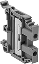
Modular DIN-Rail Mount Terminal Blocks
 |
Mix and match these terminal blocks to get the exact number of circuits you need in a single setup. Add blocks for thermocouples, fuses, and grounding wire as needed. The blocks clip side by side onto DIN rail in control panels, creating tidy rows of circuits that you can identify and access on the spot.
The screw-clamp terminals flatten your wire so it stays put when vibrated or pulled. If you need to change wiring frequently without adjusting a screw, consider a quick-connect terminal block with spring-clamp or lever-clamp terminals.
Terminal Blocks with Screw-Clamp Terminals
 |
Covers—Snap onto the exposed side of a terminal block to prevent accidental contact with a live wire.
End Stops—Mount at the end of a group of terminal blocks so they don't slide when vibrated or bumped.
Bar Jumpers—Metal poles create an electrical connection between blocks, so you can connect multiple components with a single wire. Blocks must be the same width for the jumpers to fit. Cut jumpers to size with a hacksaw or high-force wire cutter. Add covers so jumpers don't touch the screws on the outermost blocks.
Insulation—Terminal blocks with insulated jumpers maintain their IP20 rating to prevent shocks and short circuits. Blocks with noninsulated jumpers lose their IP20 rating for touch protection because the jumpers introduce exposed metal to the circuit.
Terminal Blocks | Covers | End Stops | Bar Jumpers | ||||||||||||||||||||||||||||||||||||||||||||||||||||||||||||||||||||||||||||||||||||||||||||||||
|---|---|---|---|---|---|---|---|---|---|---|---|---|---|---|---|---|---|---|---|---|---|---|---|---|---|---|---|---|---|---|---|---|---|---|---|---|---|---|---|---|---|---|---|---|---|---|---|---|---|---|---|---|---|---|---|---|---|---|---|---|---|---|---|---|---|---|---|---|---|---|---|---|---|---|---|---|---|---|---|---|---|---|---|---|---|---|---|---|---|---|---|---|---|---|---|---|---|---|---|
Each | |||||||||||||||||||||||||||||||||||||||||||||||||||||||||||||||||||||||||||||||||||||||||||||||||||
No. of Circuits | No. of Terminals per Circuit | For Wire Ga. | Wd., mm | Ht., mm | For DIN Rail Trade Size | Enclosure Rating | Choose a Color | 1-24 | 25-Up | Each | Each | Insulation | Each | ||||||||||||||||||||||||||||||||||||||||||||||||||||||||||||||||||||||||||||||||||||||
380V AC—22 amp per Circuit | |||||||||||||||||||||||||||||||||||||||||||||||||||||||||||||||||||||||||||||||||||||||||||||||||||
| 3 | 2 | 20 to 12 | 6 | 81 | 3 | IP20 | Gray | 00000000 | 00000 | 00000 | 00000000 | 00000 | 0000000 | 00000 | Noninsulated | 00000000 | 00000 | ||||||||||||||||||||||||||||||||||||||||||||||||||||||||||||||||||||||||||||||||||
600V AC—32 amp per Circuit | |||||||||||||||||||||||||||||||||||||||||||||||||||||||||||||||||||||||||||||||||||||||||||||||||||
| 1 | 6 | 22 to 12 | 6 | 87.5 | 1, 3 | IP20 | Black | 00000000 | 00000 | 00000 | ——— | 0 | ——— | 0 | — | ——— | 0 | ||||||||||||||||||||||||||||||||||||||||||||||||||||||||||||||||||||||||||||||||||
630V AC/630V DC—24 amp per Circuit | |||||||||||||||||||||||||||||||||||||||||||||||||||||||||||||||||||||||||||||||||||||||||||||||||||
| 2 | 2 | 22 to 12 | 5 | 65.5 | 1, 3 | IP20 | Beige | 00000000 | 0000 | 0000 | 0000000 | 0000 | 00000000 | 0000 | Insulated | 00000000 | 00000 | ||||||||||||||||||||||||||||||||||||||||||||||||||||||||||||||||||||||||||||||||||
| 2 | 2 | 22 to 12 | 5 | 65.5 | 1, 3 | IP20 | Blue | 00000000 | 0000 | 0000 | 0000000 | 0000 | 00000000 | 0000 | Insulated | 00000000 | 00000 | ||||||||||||||||||||||||||||||||||||||||||||||||||||||||||||||||||||||||||||||||||
| 2 | 2 | 22 to 12 | 5 | 65.5 | 1, 3 | IP20 | Gray | 00000000 | 0000 | 0000 | 0000000 | 0000 | 00000000 | 0000 | Insulated | 00000000 | 00000 | ||||||||||||||||||||||||||||||||||||||||||||||||||||||||||||||||||||||||||||||||||
800V AC—32 amp per Circuit | |||||||||||||||||||||||||||||||||||||||||||||||||||||||||||||||||||||||||||||||||||||||||||||||||||
| 2 | 2 | 22 to 12 | 6 | 65.5 | 1, 3 | IP20 | Beige , Black , Blue , Gray , Green , Orange , Red , White , Yellow | 0000000 | 0000 | 0000 | 0000000 | 0000 | 0000000 | 0000 | Noninsulated | 0000000 | 00000 | ||||||||||||||||||||||||||||||||||||||||||||||||||||||||||||||||||||||||||||||||||
800V AC/800V DC—32 amp per Circuit | |||||||||||||||||||||||||||||||||||||||||||||||||||||||||||||||||||||||||||||||||||||||||||||||||||
| 1 | 3 | 22 to 10 | 6 | 51.5 | 1, 3 | IP20 | Gray | 00000000 | 0000 | 0000 | 00000000 | 0000 | 0000000 | 0000 | Insulated | 00000000 | 00000 | ||||||||||||||||||||||||||||||||||||||||||||||||||||||||||||||||||||||||||||||||||
| 1 | 4 | 22 to 10 | 6 | 63.5 | 1, 3 | IP20 | Gray | 00000000 | 0000 | 0000 | 00000000 | 0000 | 0000000 | 0000 | Insulated | 00000000 | 00000 | ||||||||||||||||||||||||||||||||||||||||||||||||||||||||||||||||||||||||||||||||||
800V AC—41 amp per Circuit | |||||||||||||||||||||||||||||||||||||||||||||||||||||||||||||||||||||||||||||||||||||||||||||||||||
| 2 | 2 | 18 to 8 | 8 | 88 | 1, 3 | IP20 | Gray | 00000000 | 0000 | 0000 | 00000000 | 0000 | 0000000 | 0000 | Noninsulated | 0000000 | 00000 | ||||||||||||||||||||||||||||||||||||||||||||||||||||||||||||||||||||||||||||||||||
1,000V AC—24 amp per Circuit | |||||||||||||||||||||||||||||||||||||||||||||||||||||||||||||||||||||||||||||||||||||||||||||||||||
| 1 | 2 | 22 to 12 | 5 | 44.5 | 1, 3 | IP20 | Beige , Black , Blue , Gray , Orange , Red , White , Yellow | 00000000 | 0000 | 0000 | 0000000 | 0000 | 0000000 | 0000 | Noninsulated | 00000000 | 0000 | ||||||||||||||||||||||||||||||||||||||||||||||||||||||||||||||||||||||||||||||||||
1,000V AC—32 amp per Circuit | |||||||||||||||||||||||||||||||||||||||||||||||||||||||||||||||||||||||||||||||||||||||||||||||||||
| 1 | 2 | 22 to 10 | 6 | 44.5 | 1, 3 | IP20 | Beige , Black , Blue , Gray , Green , Orange , Red , White , Yellow | 0000000 | 0000 | 0000 | 0000000 | 0000 | 0000000 | 0000 | Noninsulated | 0000000 | 0000 | ||||||||||||||||||||||||||||||||||||||||||||||||||||||||||||||||||||||||||||||||||
1,000V AC—41 amp per Circuit | |||||||||||||||||||||||||||||||||||||||||||||||||||||||||||||||||||||||||||||||||||||||||||||||||||
| 1 | 2 | 22 to 8 | 8 | 44.5 | 1, 3 | IP20 | Beige , Black , Blue , Gray , Green , Orange , Red , White , Yellow | 0000000 | 0000 | 0000 | 0000000 | 0000 | 0000000 | 0000 | Noninsulated | 0000000 | 00000 | ||||||||||||||||||||||||||||||||||||||||||||||||||||||||||||||||||||||||||||||||||
1,000V AC—57 amp per Circuit | |||||||||||||||||||||||||||||||||||||||||||||||||||||||||||||||||||||||||||||||||||||||||||||||||||
| 1 | 2 | 20 to 6 | 10 | 44.5 | 1, 3 | IP20 | Beige , Black , Blue , Gray , Red , White , Yellow | 0000000 | 0000 | 0000 | 0000000 | 0000 | 0000000 | 0000 | Noninsulated | 0000000 | 00000 | ||||||||||||||||||||||||||||||||||||||||||||||||||||||||||||||||||||||||||||||||||
1,000V AC—76 amp per Circuit | |||||||||||||||||||||||||||||||||||||||||||||||||||||||||||||||||||||||||||||||||||||||||||||||||||
| 1 | 2 | 18 to 6 | 12 | 45.5 | 1, 3 | IP20 | Black , Blue , Gray , Red , White , Yellow | 00000000 | 0000 | 0000 | 00000000 | 0000 | 0000000 | 0000 | Noninsulated | 00000000 | 00000 | ||||||||||||||||||||||||||||||||||||||||||||||||||||||||||||||||||||||||||||||||||
1,000V AC—125 amp per Circuit | |||||||||||||||||||||||||||||||||||||||||||||||||||||||||||||||||||||||||||||||||||||||||||||||||||
| 1 | 2 | 10 to 1/0 | 16 | 49 | 1, 3 | IP20 | Black , Blue , Gray , Red , White , Yellow | 00000000 | 0000 | 0000 | ——— | 0 | 0000000 | 0000 | Noninsulated | 00000000 | 00000 | ||||||||||||||||||||||||||||||||||||||||||||||||||||||||||||||||||||||||||||||||||
Each | |||||||||||||||||||||||||||||||||||||||||||||||||||||||||||||||||||||||||||||||||||||||||||||||||||
|---|---|---|---|---|---|---|---|---|---|---|---|---|---|---|---|---|---|---|---|---|---|---|---|---|---|---|---|---|---|---|---|---|---|---|---|---|---|---|---|---|---|---|---|---|---|---|---|---|---|---|---|---|---|---|---|---|---|---|---|---|---|---|---|---|---|---|---|---|---|---|---|---|---|---|---|---|---|---|---|---|---|---|---|---|---|---|---|---|---|---|---|---|---|---|---|---|---|---|---|
For No. of Circuits | For Terminal Block Wd., mm | Number Range | Markers per Card | Color | 1-24 | 25-Up | |||||||||||||||||||||||||||||||||||||||||||||||||||||||||||||||||||||||||||||||||||||||||||||
Blank | |||||||||||||||||||||||||||||||||||||||||||||||||||||||||||||||||||||||||||||||||||||||||||||||||||
| 1, 2 | 5 | — | 100 | White | 00000000 | 00000 | 00000 | ||||||||||||||||||||||||||||||||||||||||||||||||||||||||||||||||||||||||||||||||||||||||||||
| 1, 2 | 6 | — | 100 | White | 0000000 | 0000 | 0000 | ||||||||||||||||||||||||||||||||||||||||||||||||||||||||||||||||||||||||||||||||||||||||||||
| 1, 2 | 8, 10, 12, 13, 16, 22 | — | 100 | White | 00000000 | 0000 | 0000 | ||||||||||||||||||||||||||||||||||||||||||||||||||||||||||||||||||||||||||||||||||||||||||||
Numbered for Horizontal Rails | |||||||||||||||||||||||||||||||||||||||||||||||||||||||||||||||||||||||||||||||||||||||||||||||||||
| 1, 2 | 5 | 1 to 100 | 100 | White | 0000000 | 0000 | 0000 | ||||||||||||||||||||||||||||||||||||||||||||||||||||||||||||||||||||||||||||||||||||||||||||
| 1, 2 | 5 | 101 to 200 | 100 | White | 0000000 | 0000 | 0000 | ||||||||||||||||||||||||||||||||||||||||||||||||||||||||||||||||||||||||||||||||||||||||||||
| 1, 2 | 6 | 1 to 100 | 100 | White | 0000000 | 0000 | 0000 | ||||||||||||||||||||||||||||||||||||||||||||||||||||||||||||||||||||||||||||||||||||||||||||
| 1, 2 | 6 | 101 to 200 | 100 | White | 0000000 | 0000 | 0000 | ||||||||||||||||||||||||||||||||||||||||||||||||||||||||||||||||||||||||||||||||||||||||||||
| 1, 2 | 8, 10, 12, 13, 16, 22 | 1 to 100 | 100 | White | 00000000 | 0000 | 0000 | ||||||||||||||||||||||||||||||||||||||||||||||||||||||||||||||||||||||||||||||||||||||||||||
| 1, 2 | 8, 10, 12, 13, 16, 22 | 101 to 200 | 100 | White | 00000000 | 0000 | 0000 | ||||||||||||||||||||||||||||||||||||||||||||||||||||||||||||||||||||||||||||||||||||||||||||
Numbered for Vertical Rails | |||||||||||||||||||||||||||||||||||||||||||||||||||||||||||||||||||||||||||||||||||||||||||||||||||
| 1, 2 | 5 | 1 to 100 | 100 | White | 0000000 | 0000 | 0000 | ||||||||||||||||||||||||||||||||||||||||||||||||||||||||||||||||||||||||||||||||||||||||||||
| 1, 2 | 5 | 101 to 200 | 100 | White | 0000000 | 0000 | 0000 | ||||||||||||||||||||||||||||||||||||||||||||||||||||||||||||||||||||||||||||||||||||||||||||
| 1, 2 | 6 | 1 to 100 | 100 | White | 0000000 | 0000 | 0000 | ||||||||||||||||||||||||||||||||||||||||||||||||||||||||||||||||||||||||||||||||||||||||||||
| 1, 2 | 6 | 101 to 200 | 100 | White | 0000000 | 0000 | 0000 | ||||||||||||||||||||||||||||||||||||||||||||||||||||||||||||||||||||||||||||||||||||||||||||
| 1, 2 | 8, 10, 12, 13, 16, 22 | 1 to 100 | 100 | White | 00000000 | 0000 | 0000 | ||||||||||||||||||||||||||||||||||||||||||||||||||||||||||||||||||||||||||||||||||||||||||||
| 1, 2 | 8, 10, 12, 13, 16, 22 | 101 to 200 | 100 | White | 00000000 | 0000 | 0000 | ||||||||||||||||||||||||||||||||||||||||||||||||||||||||||||||||||||||||||||||||||||||||||||
Ground Terminal Blocks with Screw-Clamp Terminals
 |
Connect grounding wire to DIN rail so fault currents can safely flow to ground. These terminal blocks should only be used for grounding circuits.
End Stops—Mount at the end of a group of terminal blocks so they don't slide when vibrated or bumped.
Terminal Blocks | End Stops | |||||||||||||
|---|---|---|---|---|---|---|---|---|---|---|---|---|---|---|
Each | ||||||||||||||
No. of Circuits | No. of Terminals per Circuit | For Wire Ga. | Wd., mm | Ht., mm | Color | For DIN Rail Trade Size | Enclosure Rating | 1-24 | 25-Up | Each | ||||
| 1 | 2 | 22 to 12 | 5 | 43.5 | Green/Yellow | 1, 3 | IP20 | 00000000 | 00000 | 00000 | 0000000 | 00000 | ||
| 1 | 2 | 22 to 12 | 6 | 43.8 | Green/Yellow | 1, 3 | IP20 | 0000000 | 0000 | 0000 | 0000000 | 0000 | ||
| 1 | 2 | 22 to 8 | 8 | 43.8 | Green/Yellow | 1, 3 | IP20 | 0000000 | 0000 | 0000 | 0000000 | 0000 | ||
| 1 | 2 | 20 to 6 | 10 | 43.8 | Green/Yellow | 1, 3 | IP20 | 0000000 | 0000 | 0000 | 0000000 | 0000 | ||
| 1 | 2 | 14 to 4 | 12 | 49.5 | Green/Yellow | 1, 3 | IP20 | 00000000 | 0000 | 0000 | 0000000 | 0000 | ||
| 1 | 2 | 8 to 1/0 | 16 | 49 | Green/Yellow | 1, 3 | IP20 | 00000000 | 00000 | 0000 | 0000000 | 0000 | ||
| 1 | 4 | 22 to 10 | 6 | 63.5 | Green/Yellow | 1, 3 | IP20 | 00000000 | 0000 | 0000 | 0000000 | 0000 | ||
| 1 | 7 | 22 to 12 | 6 | 90 | Green/Yellow | 1, 3 | IP20 | 00000000 | 00000 | 00000 | 00000000 | 0000 | ||
Each | |||||||||||||||||||||||||||||||||||||||||||||||||||||||||||||||||||||||||||||||||||||||||||||||||||
|---|---|---|---|---|---|---|---|---|---|---|---|---|---|---|---|---|---|---|---|---|---|---|---|---|---|---|---|---|---|---|---|---|---|---|---|---|---|---|---|---|---|---|---|---|---|---|---|---|---|---|---|---|---|---|---|---|---|---|---|---|---|---|---|---|---|---|---|---|---|---|---|---|---|---|---|---|---|---|---|---|---|---|---|---|---|---|---|---|---|---|---|---|---|---|---|---|---|---|---|
For No. of Circuits | For Terminal Block Wd., mm | Number Range | Markers per Card | Color | 1-24 | 25-Up | |||||||||||||||||||||||||||||||||||||||||||||||||||||||||||||||||||||||||||||||||||||||||||||
Blank | |||||||||||||||||||||||||||||||||||||||||||||||||||||||||||||||||||||||||||||||||||||||||||||||||||
| 1, 2 | 5 | — | 100 | White | 00000000 | 00000 | 00000 | ||||||||||||||||||||||||||||||||||||||||||||||||||||||||||||||||||||||||||||||||||||||||||||
| 1, 2 | 6 | — | 100 | White | 0000000 | 0000 | 0000 | ||||||||||||||||||||||||||||||||||||||||||||||||||||||||||||||||||||||||||||||||||||||||||||
| 1, 2 | 8, 10, 12, 13, 16, 22 | — | 100 | White | 00000000 | 0000 | 0000 | ||||||||||||||||||||||||||||||||||||||||||||||||||||||||||||||||||||||||||||||||||||||||||||
Numbered for Horizontal Rails | |||||||||||||||||||||||||||||||||||||||||||||||||||||||||||||||||||||||||||||||||||||||||||||||||||
| 1, 2 | 5 | 1 to 100 | 100 | White | 0000000 | 0000 | 0000 | ||||||||||||||||||||||||||||||||||||||||||||||||||||||||||||||||||||||||||||||||||||||||||||
| 1, 2 | 5 | 101 to 200 | 100 | White | 0000000 | 0000 | 0000 | ||||||||||||||||||||||||||||||||||||||||||||||||||||||||||||||||||||||||||||||||||||||||||||
| 1, 2 | 6 | 1 to 100 | 100 | White | 0000000 | 0000 | 0000 | ||||||||||||||||||||||||||||||||||||||||||||||||||||||||||||||||||||||||||||||||||||||||||||
| 1, 2 | 6 | 101 to 200 | 100 | White | 0000000 | 0000 | 0000 | ||||||||||||||||||||||||||||||||||||||||||||||||||||||||||||||||||||||||||||||||||||||||||||
| 1, 2 | 8, 10, 12, 13, 16, 22 | 1 to 100 | 100 | White | 00000000 | 0000 | 0000 | ||||||||||||||||||||||||||||||||||||||||||||||||||||||||||||||||||||||||||||||||||||||||||||
| 1, 2 | 8, 10, 12, 13, 16, 22 | 101 to 200 | 100 | White | 00000000 | 0000 | 0000 | ||||||||||||||||||||||||||||||||||||||||||||||||||||||||||||||||||||||||||||||||||||||||||||
Numbered for Vertical Rails | |||||||||||||||||||||||||||||||||||||||||||||||||||||||||||||||||||||||||||||||||||||||||||||||||||
| 1, 2 | 5 | 1 to 100 | 100 | White | 0000000 | 0000 | 0000 | ||||||||||||||||||||||||||||||||||||||||||||||||||||||||||||||||||||||||||||||||||||||||||||
| 1, 2 | 5 | 101 to 200 | 100 | White | 0000000 | 0000 | 0000 | ||||||||||||||||||||||||||||||||||||||||||||||||||||||||||||||||||||||||||||||||||||||||||||
| 1, 2 | 6 | 1 to 100 | 100 | White | 0000000 | 0000 | 0000 | ||||||||||||||||||||||||||||||||||||||||||||||||||||||||||||||||||||||||||||||||||||||||||||
| 1, 2 | 6 | 101 to 200 | 100 | White | 0000000 | 0000 | 0000 | ||||||||||||||||||||||||||||||||||||||||||||||||||||||||||||||||||||||||||||||||||||||||||||
| 1, 2 | 8, 10, 12, 13, 16, 22 | 1 to 100 | 100 | White | 00000000 | 0000 | 0000 | ||||||||||||||||||||||||||||||||||||||||||||||||||||||||||||||||||||||||||||||||||||||||||||
| 1, 2 | 8, 10, 12, 13, 16, 22 | 101 to 200 | 100 | White | 00000000 | 0000 | 0000 | ||||||||||||||||||||||||||||||||||||||||||||||||||||||||||||||||||||||||||||||||||||||||||||
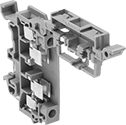
Fuse Terminal Blocks with Screw-Clamp Terminals
 |
Install a fuse in the built-in fuse holder so excess current doesn't damage your equipment. If the current exceeds the limit, the fuse will blow and cut power to connected components.
Blown Fuse Indicator—A light goes on when the fuse blows, so you can spot an overloaded circuit without cutting power or touching equipment.
Covers—Snap onto the exposed side of a terminal block to prevent accidental contact with a live wire.
End Stops—Mount at the end of a group of terminal blocks so they don't slide when vibrated or bumped.
Bar Jumpers—Metal poles create an electrical connection between blocks, so you can connect multiple components with a single wire. Blocks must be the same width for the jumpers to fit. Cut jumpers to size with a hacksaw or high-force wire cutter. Add covers so jumpers don't touch the screws on the outermost blocks.
Insulation—Terminal blocks with insulated jumpers maintain their IP20 rating to prevent shocks and short circuits. Blocks with noninsulated jumpers lose their IP20 rating for touch protection because the jumpers introduce exposed metal to the circuit.
Terminal Blocks | Covers | End Stops | Bar Jumpers | ||||||||||||||||||||||||||||||||||||||||||||||||||||||||||||||||||||||||||||||||||||||||||||||||
|---|---|---|---|---|---|---|---|---|---|---|---|---|---|---|---|---|---|---|---|---|---|---|---|---|---|---|---|---|---|---|---|---|---|---|---|---|---|---|---|---|---|---|---|---|---|---|---|---|---|---|---|---|---|---|---|---|---|---|---|---|---|---|---|---|---|---|---|---|---|---|---|---|---|---|---|---|---|---|---|---|---|---|---|---|---|---|---|---|---|---|---|---|---|---|---|---|---|---|---|
For Fuse | Each | ||||||||||||||||||||||||||||||||||||||||||||||||||||||||||||||||||||||||||||||||||||||||||||||||||
No. of Circuits | No. of Terminals per Circuit | For Wire Ga. | Wd., mm | Ht., mm | Trade Size | Overall Dia. | Overall Lg. | Type | Circuit Status Indicator Type | Blown Fuse Indicator Voltage | For DIN Rail Trade Size | Enclosure Rating | Choose a Color | 1-24 | 25-Up | Each | Each | Insulation | Each | ||||||||||||||||||||||||||||||||||||||||||||||||||||||||||||||||||||||||||||||||
300V AC/300V DC—6.3 amp per Circuit | |||||||||||||||||||||||||||||||||||||||||||||||||||||||||||||||||||||||||||||||||||||||||||||||||||
| 2 1 (Ground) | 2 1 (Ground) | 20 to 12 | 8 | 99 | — | 5 mm | 20 mm | Ceramic, Glass | — | — | 3 | IP20 | Gray | 00000000 | 000000 | 000000 | 00000000 | 00000 | 00000000 | 00000 | Noninsulated | 0000000 | 000000 | ||||||||||||||||||||||||||||||||||||||||||||||||||||||||||||||||||||||||||||
| 2 1 (Ground) | 2 1 (Ground) | 20 to 12 | 8 | 99 | — | 5 mm | 20 mm | Ceramic, Glass | Blown Fuse | 24V DC 60V DC 110V AC | 3 | IP20 | Gray | 00000000 | 00000 | 00000 | 00000000 | 0000 | 00000000 | 0000 | Noninsulated | 0000000 | 00000 | ||||||||||||||||||||||||||||||||||||||||||||||||||||||||||||||||||||||||||||
| 2 1 (Ground) | 2 1 (Ground) | 20 to 12 | 8 | 99 | — | 5 mm | 20 mm | Ceramic, Glass | Blown Fuse | 110V AC 230V AC | 3 | IP20 | Gray | 00000000 | 00000 | 00000 | 00000000 | 0000 | 00000000 | 0000 | Noninsulated | 0000000 | 00000 | ||||||||||||||||||||||||||||||||||||||||||||||||||||||||||||||||||||||||||||
400V AC/400V DC—6.3 amp per Circuit | |||||||||||||||||||||||||||||||||||||||||||||||||||||||||||||||||||||||||||||||||||||||||||||||||||
| 1 | 2 | 22 to 12 | 8 | 56 | — | 5 mm | 20 mm | Ceramic, Glass | Blown Fuse | 24V AC 24V DC | 1, 3 | IP20 | Gray | 00000000 | 00000 | 00000 | 0000000 | 0000 | 0000000 | 0000 | — | ——— | 0 | ||||||||||||||||||||||||||||||||||||||||||||||||||||||||||||||||||||||||||||
| 1 | 2 | 22 to 12 | 8 | 56 | — | 5 mm | 20 mm | Ceramic, Glass | Blown Fuse | 110V AC 230V AC | 1, 3 | IP20 | Gray | 00000000 | 00000 | 00000 | 0000000 | 0000 | 0000000 | 0000 | — | ——— | 0 | ||||||||||||||||||||||||||||||||||||||||||||||||||||||||||||||||||||||||||||
600V AC—6.3 amp per Circuit | |||||||||||||||||||||||||||||||||||||||||||||||||||||||||||||||||||||||||||||||||||||||||||||||||||
| 2 | 2 | 24 to 12 | 8 | 85.5 | — | 5 mm | 20 mm | Ceramic, Glass | Blown Fuse | 110V AC 230V AC | 1, 3 | IP20 | Gray | 00000000 | 00000 | 00000 | 00000000 | 0000 | 00000000 | 0000 | Insulated | 00000000 | 00000 | ||||||||||||||||||||||||||||||||||||||||||||||||||||||||||||||||||||||||||||
| 2 | 2 | 12 | 8 | 85.5 | — | 5 mm | 20 mm | Ceramic, Glass | Blown Fuse | 24V AC 24V DC | 1, 3 | IP20 | Gray | 00000000 | 00000 | 00000 | 00000000 | 0000 | 00000000 | 0000 | Insulated | 00000000 | 00000 | ||||||||||||||||||||||||||||||||||||||||||||||||||||||||||||||||||||||||||||
630V AC—6.3 amp per Circuit | |||||||||||||||||||||||||||||||||||||||||||||||||||||||||||||||||||||||||||||||||||||||||||||||||||
| 1 | 2 | 22 to 12 | 8 | 56 | — | 5 mm | 20 mm | Ceramic, Glass | — | — | 1, 3 | IP20 | Gray , Orange | 0000000 | 0000 | 0000 | 0000000 | 0000 | 0000000 | 0000 | — | ——— | 0 | ||||||||||||||||||||||||||||||||||||||||||||||||||||||||||||||||||||||||||||
630V AC/630V DC—6.3 amp per Circuit | |||||||||||||||||||||||||||||||||||||||||||||||||||||||||||||||||||||||||||||||||||||||||||||||||||
| 2 | 2 | 24 to 12 | 8 | 85.5 | — | 5 mm | 20 mm | Ceramic, Glass | — | — | 1, 3 | IP20 | Gray | 00000000 | 00000 | 00000 | 00000000 | 0000 | 00000000 | 0000 | Insulated | 00000000 | 00000 | ||||||||||||||||||||||||||||||||||||||||||||||||||||||||||||||||||||||||||||
800V AC/800V DC—10 amp per Circuit | |||||||||||||||||||||||||||||||||||||||||||||||||||||||||||||||||||||||||||||||||||||||||||||||||||
| 1 | 2 | 22 to 10 | 13 | 85.1 | 3AG | 1/4" | — | Glass | Blown Fuse | 24V AC 24V DC | 1, 3 | IP20 | Black | 00000000 | 00000 | 00000 | 0000000 | 0000 | 0000000 | 0000 | — | ——— | 0 | ||||||||||||||||||||||||||||||||||||||||||||||||||||||||||||||||||||||||||||
| 1 | 2 | 22 to 10 | 13 | 85.1 | 3AG | 1/4" | — | Glass | Blown Fuse | 110V AC 230V AC | 1, 3 | IP20 | Black | 00000000 | 00000 | 00000 | 0000000 | 0000 | 0000000 | 0000 | — | ——— | 0 | ||||||||||||||||||||||||||||||||||||||||||||||||||||||||||||||||||||||||||||
800V AC—16 amp per Circuit | |||||||||||||||||||||||||||||||||||||||||||||||||||||||||||||||||||||||||||||||||||||||||||||||||||
| 1 | 2 | 22 to 10 | 13 | 85.1 | 3AG | 1/4" | — | Glass | — | — | 1, 3 | IP20 | Black | 0000000 | 00000 | 0000 | 0000000 | 0000 | 0000000 | 0000 | — | ——— | 0 | ||||||||||||||||||||||||||||||||||||||||||||||||||||||||||||||||||||||||||||
800V AC—30 amp per Circuit | |||||||||||||||||||||||||||||||||||||||||||||||||||||||||||||||||||||||||||||||||||||||||||||||||||
| 1 | 2 | 18 to 6 | 22 | 90.7 | — | 13/32" | 1 1/2" | Cartridge | — | — | 1, 3 | IP20 | Gray | 00000000 | 00000 | 00000 | ——— | 0 | 0000000 | 0000 | — | ——— | 0 | ||||||||||||||||||||||||||||||||||||||||||||||||||||||||||||||||||||||||||||
Blank | Numbered for Horizontal Rails | Numbered for Vertical Rails |
Each | |||||||||||||||||||||||||||||||||||||||||||||||||||||||||||||||||||||||||||||||||||||||||||||||||||
|---|---|---|---|---|---|---|---|---|---|---|---|---|---|---|---|---|---|---|---|---|---|---|---|---|---|---|---|---|---|---|---|---|---|---|---|---|---|---|---|---|---|---|---|---|---|---|---|---|---|---|---|---|---|---|---|---|---|---|---|---|---|---|---|---|---|---|---|---|---|---|---|---|---|---|---|---|---|---|---|---|---|---|---|---|---|---|---|---|---|---|---|---|---|---|---|---|---|---|---|
For No. of Circuits | For Terminal Block Wd., mm | Number Range | Markers per Card | Color | 1-24 | 25-Up | |||||||||||||||||||||||||||||||||||||||||||||||||||||||||||||||||||||||||||||||||||||||||||||
Blank | |||||||||||||||||||||||||||||||||||||||||||||||||||||||||||||||||||||||||||||||||||||||||||||||||||
| 1, 2 | 8, 10, 12, 13, 16, 22 | — | 100 | White | 00000000 | 00000 | 00000 | ||||||||||||||||||||||||||||||||||||||||||||||||||||||||||||||||||||||||||||||||||||||||||||
Numbered for Horizontal Rails | |||||||||||||||||||||||||||||||||||||||||||||||||||||||||||||||||||||||||||||||||||||||||||||||||||
| 1, 2 | 8, 10, 12, 13, 16, 22 | 1 to 100 | 100 | White | 00000000 | 0000 | 0000 | ||||||||||||||||||||||||||||||||||||||||||||||||||||||||||||||||||||||||||||||||||||||||||||
| 1, 2 | 8, 10, 12, 13, 16, 22 | 101 to 200 | 100 | White | 00000000 | 0000 | 0000 | ||||||||||||||||||||||||||||||||||||||||||||||||||||||||||||||||||||||||||||||||||||||||||||
Numbered for Vertical Rails | |||||||||||||||||||||||||||||||||||||||||||||||||||||||||||||||||||||||||||||||||||||||||||||||||||
| 1, 2 | 8, 10, 12, 13, 16, 22 | 1 to 100 | 100 | White | 00000000 | 0000 | 0000 | ||||||||||||||||||||||||||||||||||||||||||||||||||||||||||||||||||||||||||||||||||||||||||||
| 1, 2 | 8, 10, 12, 13, 16, 22 | 101 to 200 | 100 | White | 00000000 | 0000 | 0000 | ||||||||||||||||||||||||||||||||||||||||||||||||||||||||||||||||||||||||||||||||||||||||||||
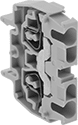
Disconnect Terminal Blocks with Screw-Clamp Terminals
 |
Test and troubleshoot circuits without removing any wire. Flip the tab by hand or with a screwdriver to open and close the circuit.
Covers—Snap onto the exposed side of a terminal block to prevent accidental contact with a live wire.
End Stops—Mount at the end of a group of terminal blocks so they don't slide when vibrated or bumped.
Adjacent Jumpers—Metal poles create an electrical connection between adjacent terminal blocks, so you can connect multiple components with a single wire. Blocks must be the same width for the jumpers to fit.
Insulation—Terminal blocks with insulated jumpers maintain their IP20 rating to prevent shocks and short circuits. Blocks with noninsulated jumpers lose their IP20 rating for touch protection because the jumpers introduce exposed metal to the circuit.
Terminal Blocks | Covers | End Stops | Adjacent Jumpers | ||||||||||||||||||||||||||||||||||||||||||||||||||||||||||||||||||||||||||||||||||||||||||||||||
|---|---|---|---|---|---|---|---|---|---|---|---|---|---|---|---|---|---|---|---|---|---|---|---|---|---|---|---|---|---|---|---|---|---|---|---|---|---|---|---|---|---|---|---|---|---|---|---|---|---|---|---|---|---|---|---|---|---|---|---|---|---|---|---|---|---|---|---|---|---|---|---|---|---|---|---|---|---|---|---|---|---|---|---|---|---|---|---|---|---|---|---|---|---|---|---|---|---|---|---|
Each | |||||||||||||||||||||||||||||||||||||||||||||||||||||||||||||||||||||||||||||||||||||||||||||||||||
No. of Circuits | No. of Terminals per Circuit | For Wire Ga. | Wd., mm | Ht., mm | Color | For DIN Rail Trade Size | Enclosure Rating | 1-24 | 25-Up | Each | Each | Insulation | Each | ||||||||||||||||||||||||||||||||||||||||||||||||||||||||||||||||||||||||||||||||||||||
320V AC/320V DC—10 amp per Circuit | |||||||||||||||||||||||||||||||||||||||||||||||||||||||||||||||||||||||||||||||||||||||||||||||||||
| 1 | 2 | 12 | 5 | 44.5 | Gray/Orange | 1, 3 | IP20 | 00000000 | 00000 | 00000 | 0000000 | 00000 | 0000000 | 00000 | Noninsulated | 00000000 | 00000 | ||||||||||||||||||||||||||||||||||||||||||||||||||||||||||||||||||||||||||||||||||
400V AC—15 amp per Circuit | |||||||||||||||||||||||||||||||||||||||||||||||||||||||||||||||||||||||||||||||||||||||||||||||||||
| 1 | 2 | 22 to 10 | 8 | 47 | Gray | 1, 3 | IP20 | 0000000 | 0000 | 0000 | 00000000 | 0000 | 0000000 | 0000 | Insulated | 00000000 | 0000 | ||||||||||||||||||||||||||||||||||||||||||||||||||||||||||||||||||||||||||||||||||
400V AC—20 amp per Circuit | |||||||||||||||||||||||||||||||||||||||||||||||||||||||||||||||||||||||||||||||||||||||||||||||||||
| 1 | 2 | 22 to 10 | 6 | 44.5 | Gray | 1, 3 | IP20 | 0000000 | 0000 | 0000 | 00000000 | 0000 | 0000000 | 0000 | Insulated | 00000000 | 0000 | ||||||||||||||||||||||||||||||||||||||||||||||||||||||||||||||||||||||||||||||||||
Each | |||||||||||||||||||||||||||||||||||||||||||||||||||||||||||||||||||||||||||||||||||||||||||||||||||
|---|---|---|---|---|---|---|---|---|---|---|---|---|---|---|---|---|---|---|---|---|---|---|---|---|---|---|---|---|---|---|---|---|---|---|---|---|---|---|---|---|---|---|---|---|---|---|---|---|---|---|---|---|---|---|---|---|---|---|---|---|---|---|---|---|---|---|---|---|---|---|---|---|---|---|---|---|---|---|---|---|---|---|---|---|---|---|---|---|---|---|---|---|---|---|---|---|---|---|---|
For No. of Circuits | For Terminal Block Wd., mm | Number Range | Markers per Card | Color | 1-24 | 25-Up | |||||||||||||||||||||||||||||||||||||||||||||||||||||||||||||||||||||||||||||||||||||||||||||
Blank | |||||||||||||||||||||||||||||||||||||||||||||||||||||||||||||||||||||||||||||||||||||||||||||||||||
| 1, 2 | 5 | — | 100 | White | 00000000 | 00000 | 00000 | ||||||||||||||||||||||||||||||||||||||||||||||||||||||||||||||||||||||||||||||||||||||||||||
| 1, 2 | 6 | — | 100 | White | 0000000 | 0000 | 0000 | ||||||||||||||||||||||||||||||||||||||||||||||||||||||||||||||||||||||||||||||||||||||||||||
| 1, 2 | 8, 10, 12, 13, 16, 22 | — | 100 | White | 00000000 | 0000 | 0000 | ||||||||||||||||||||||||||||||||||||||||||||||||||||||||||||||||||||||||||||||||||||||||||||
Numbered for Horizontal Rails | |||||||||||||||||||||||||||||||||||||||||||||||||||||||||||||||||||||||||||||||||||||||||||||||||||
| 1, 2 | 5 | 1 to 100 | 100 | White | 0000000 | 0000 | 0000 | ||||||||||||||||||||||||||||||||||||||||||||||||||||||||||||||||||||||||||||||||||||||||||||
| 1, 2 | 5 | 101 to 200 | 100 | White | 0000000 | 0000 | 0000 | ||||||||||||||||||||||||||||||||||||||||||||||||||||||||||||||||||||||||||||||||||||||||||||
| 1, 2 | 6 | 1 to 100 | 100 | White | 0000000 | 0000 | 0000 | ||||||||||||||||||||||||||||||||||||||||||||||||||||||||||||||||||||||||||||||||||||||||||||
| 1, 2 | 6 | 101 to 200 | 100 | White | 0000000 | 0000 | 0000 | ||||||||||||||||||||||||||||||||||||||||||||||||||||||||||||||||||||||||||||||||||||||||||||
| 1, 2 | 8, 10, 12, 13, 16, 22 | 1 to 100 | 100 | White | 00000000 | 0000 | 0000 | ||||||||||||||||||||||||||||||||||||||||||||||||||||||||||||||||||||||||||||||||||||||||||||
| 1, 2 | 8, 10, 12, 13, 16, 22 | 101 to 200 | 100 | White | 00000000 | 0000 | 0000 | ||||||||||||||||||||||||||||||||||||||||||||||||||||||||||||||||||||||||||||||||||||||||||||
Numbered for Vertical Rails | |||||||||||||||||||||||||||||||||||||||||||||||||||||||||||||||||||||||||||||||||||||||||||||||||||
| 1, 2 | 5 | 1 to 100 | 100 | White | 0000000 | 0000 | 0000 | ||||||||||||||||||||||||||||||||||||||||||||||||||||||||||||||||||||||||||||||||||||||||||||
| 1, 2 | 5 | 101 to 200 | 100 | White | 0000000 | 0000 | 0000 | ||||||||||||||||||||||||||||||||||||||||||||||||||||||||||||||||||||||||||||||||||||||||||||
| 1, 2 | 6 | 1 to 100 | 100 | White | 0000000 | 0000 | 0000 | ||||||||||||||||||||||||||||||||||||||||||||||||||||||||||||||||||||||||||||||||||||||||||||
| 1, 2 | 6 | 101 to 200 | 100 | White | 0000000 | 0000 | 0000 | ||||||||||||||||||||||||||||||||||||||||||||||||||||||||||||||||||||||||||||||||||||||||||||
| 1, 2 | 8, 10, 12, 13, 16, 22 | 1 to 100 | 100 | White | 00000000 | 0000 | 0000 | ||||||||||||||||||||||||||||||||||||||||||||||||||||||||||||||||||||||||||||||||||||||||||||
| 1, 2 | 8, 10, 12, 13, 16, 22 | 101 to 200 | 100 | White | 00000000 | 0000 | 0000 | ||||||||||||||||||||||||||||||||||||||||||||||||||||||||||||||||||||||||||||||||||||||||||||
Thermocouple Terminal Blocks with Screw-Clamp Terminals
 |
Run your thermocouple wire into these blocks so no signal is lost or destroyed. The metal in the terminals is compatible with multiple thermocouple wire types.
Covers—Snap onto the exposed side of a terminal block to prevent accidental contact with a live wire.
End Stops—Mount at the end of a group of terminal blocks so they don't slide when vibrated or bumped.
Terminal Blocks | Covers | End Stops | |||||||||||||||||||||||||||||||||||||||||||||||||||||||||||||||||||||||||||||||||||||||||||||||||
|---|---|---|---|---|---|---|---|---|---|---|---|---|---|---|---|---|---|---|---|---|---|---|---|---|---|---|---|---|---|---|---|---|---|---|---|---|---|---|---|---|---|---|---|---|---|---|---|---|---|---|---|---|---|---|---|---|---|---|---|---|---|---|---|---|---|---|---|---|---|---|---|---|---|---|---|---|---|---|---|---|---|---|---|---|---|---|---|---|---|---|---|---|---|---|---|---|---|---|---|
Each | |||||||||||||||||||||||||||||||||||||||||||||||||||||||||||||||||||||||||||||||||||||||||||||||||||
No. of Circuits | No. of Terminals per Circuit | For Wire Ga. | Wd., mm | Ht., mm | For Thermocouple Wire Type | Color | For DIN Rail Trade Size | Enclosure Rating | 1-24 | 25-Up | Each | Each | |||||||||||||||||||||||||||||||||||||||||||||||||||||||||||||||||||||||||||||||||||||||
500V AC/500V DC | |||||||||||||||||||||||||||||||||||||||||||||||||||||||||||||||||||||||||||||||||||||||||||||||||||
| 1 | 2 | 24 to 2 | 6 | 44.5 | J, K, T | Gray | 1, 3 | IP20 | 00000000 | 000000 | 000000 | 0000000 | 00000 | 0000000 | 00000 | ||||||||||||||||||||||||||||||||||||||||||||||||||||||||||||||||||||||||||||||||||||
Blank | Numbered for Horizontal Rails | Numbered for Vertical Rails |
Each | |||||||||||||||||||||||||||||||||||||||||||||||||||||||||||||||||||||||||||||||||||||||||||||||||||
|---|---|---|---|---|---|---|---|---|---|---|---|---|---|---|---|---|---|---|---|---|---|---|---|---|---|---|---|---|---|---|---|---|---|---|---|---|---|---|---|---|---|---|---|---|---|---|---|---|---|---|---|---|---|---|---|---|---|---|---|---|---|---|---|---|---|---|---|---|---|---|---|---|---|---|---|---|---|---|---|---|---|---|---|---|---|---|---|---|---|---|---|---|---|---|---|---|---|---|---|
For No. of Circuits | For Terminal Block Wd., mm | Number Range | Markers per Card | Color | 1-24 | 25-Up | |||||||||||||||||||||||||||||||||||||||||||||||||||||||||||||||||||||||||||||||||||||||||||||
Blank | |||||||||||||||||||||||||||||||||||||||||||||||||||||||||||||||||||||||||||||||||||||||||||||||||||
| 1, 2 | 6 | — | 100 | White | 0000000 | 00000 | 00000 | ||||||||||||||||||||||||||||||||||||||||||||||||||||||||||||||||||||||||||||||||||||||||||||
Numbered for Horizontal Rails | |||||||||||||||||||||||||||||||||||||||||||||||||||||||||||||||||||||||||||||||||||||||||||||||||||
| 1, 2 | 6 | 1 to 100 | 100 | White | 0000000 | 0000 | 0000 | ||||||||||||||||||||||||||||||||||||||||||||||||||||||||||||||||||||||||||||||||||||||||||||
| 1, 2 | 6 | 101 to 200 | 100 | White | 0000000 | 0000 | 0000 | ||||||||||||||||||||||||||||||||||||||||||||||||||||||||||||||||||||||||||||||||||||||||||||
Numbered for Vertical Rails | |||||||||||||||||||||||||||||||||||||||||||||||||||||||||||||||||||||||||||||||||||||||||||||||||||
| 1, 2 | 6 | 1 to 100 | 100 | White | 0000000 | 0000 | 0000 | ||||||||||||||||||||||||||||||||||||||||||||||||||||||||||||||||||||||||||||||||||||||||||||
| 1, 2 | 6 | 101 to 200 | 100 | White | 0000000 | 0000 | 0000 | ||||||||||||||||||||||||||||||||||||||||||||||||||||||||||||||||||||||||||||||||||||||||||||
High-Temperature Terminal Blocks
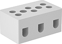 |
These ceramic terminal blocks keep their shape and strength at temperatures up to 1,200° F—over four times higher than standard blocks. Mount them to surfaces in ovens, kilns, and other heat-generating equipment.
Mounting Holes | |||||||||||||||||||||||||||||||||||||||||||||||||||||||||||||||||||||||||||||||||||||||||||||||||||
|---|---|---|---|---|---|---|---|---|---|---|---|---|---|---|---|---|---|---|---|---|---|---|---|---|---|---|---|---|---|---|---|---|---|---|---|---|---|---|---|---|---|---|---|---|---|---|---|---|---|---|---|---|---|---|---|---|---|---|---|---|---|---|---|---|---|---|---|---|---|---|---|---|---|---|---|---|---|---|---|---|---|---|---|---|---|---|---|---|---|---|---|---|---|---|---|---|---|---|---|
No. of Circuits | For Wire Ga. | Wire Connection | Terminal Size | Terminal Ctr.-to-Ctr. | Lg. | Wd. | Ht. | Max. Temp., ° F | Material | Color | Dia. | No. of | Each | ||||||||||||||||||||||||||||||||||||||||||||||||||||||||||||||||||||||||||||||||||||||
300V AC/300V DC—20 amp per Circuit | |||||||||||||||||||||||||||||||||||||||||||||||||||||||||||||||||||||||||||||||||||||||||||||||||||
| 1 | 24 to 12 | Screw Terminal | M3 | — | 7/16" | 15/16" | 3/4" | 1,200 | Ceramic | White | — | — | 0000000 | 00000 | |||||||||||||||||||||||||||||||||||||||||||||||||||||||||||||||||||||||||||||||||||||
| 2 | 24 to 12 | Screw Terminal | M3 | 5/16" | 11/16" | 15/16" | 3/4" | 1,200 | Ceramic | White | — | — | 0000000 | 0000 | |||||||||||||||||||||||||||||||||||||||||||||||||||||||||||||||||||||||||||||||||||||
| 2 | 24 to 12 | Screw Terminal | M3 | 1/2" | 15/16" | 15/16" | 3/4" | 1,200 | Ceramic | White | 0.14" | 2 | 0000000 | 0000 | |||||||||||||||||||||||||||||||||||||||||||||||||||||||||||||||||||||||||||||||||||||
| 3 | 24 to 12 | Screw Terminal | M3 | 5/16" | 1" | 15/16" | 3/4" | 1,200 | Ceramic | White | — | — | 0000000 | 0000 | |||||||||||||||||||||||||||||||||||||||||||||||||||||||||||||||||||||||||||||||||||||
| 3 | 24 to 12 | Screw Terminal | M3 | 1/2" | 1 7/16" | 15/16" | 3/4" | 1,200 | Ceramic | White | 0.14" | 2 | 0000000 | 0000 | |||||||||||||||||||||||||||||||||||||||||||||||||||||||||||||||||||||||||||||||||||||
300V AC/300V DC—30 amp per Circuit | |||||||||||||||||||||||||||||||||||||||||||||||||||||||||||||||||||||||||||||||||||||||||||||||||||
| 1 | 22 to 10 | Screw Terminal | M4 | — | 1/2" | 1" | 3/4" | 1,200 | Ceramic | White | — | — | 0000000 | 0000 | |||||||||||||||||||||||||||||||||||||||||||||||||||||||||||||||||||||||||||||||||||||
| 2 | 22 to 10 | Screw Terminal | M4 | 9/16" | 1" | 1" | 3/4" | 1,200 | Ceramic | White | 0.14" | 2 | 0000000 | 0000 | |||||||||||||||||||||||||||||||||||||||||||||||||||||||||||||||||||||||||||||||||||||
| 3 | 22 to 10 | Screw Terminal | M4 | 9/16" | 1 5/8" | 1" | 3/4" | 1,200 | Ceramic | White | 0.14" | 2 | 0000000 | 0000 | |||||||||||||||||||||||||||||||||||||||||||||||||||||||||||||||||||||||||||||||||||||
| 4 | 22 to 10 | Screw Terminal | M4 | 5/16" | 1 9/16" | 13/16" | 5/8" | 1,200 | Ceramic | White | 0.14" | 1 | 0000000 | 0000 | |||||||||||||||||||||||||||||||||||||||||||||||||||||||||||||||||||||||||||||||||||||
300V AC/300V DC—65 amp per Circuit | |||||||||||||||||||||||||||||||||||||||||||||||||||||||||||||||||||||||||||||||||||||||||||||||||||
| 2 | 18 to 6 | Screw Terminal | M4 | 11/16" | 1 1/4" | 1 1/8" | 15/16" | 1,200 | Ceramic | White | 0.14" | 2 | 0000000 | 0000 | |||||||||||||||||||||||||||||||||||||||||||||||||||||||||||||||||||||||||||||||||||||
| 3 | 18 to 6 | Screw Terminal | M4 | 11/16" | 1 7/8" | 1 1/16" | 15/16" | 1,200 | Ceramic | White | 0.14" | 2 | 0000000 | 0000 | |||||||||||||||||||||||||||||||||||||||||||||||||||||||||||||||||||||||||||||||||||||
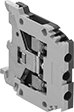
Space-Saving Modular DIN-Rail Mount Terminal Blocks
|
These handle the same voltage and power as our other modular blocks while taking up about half the vertical space. Snap them onto DIN 2 rail (also known as mini rail), which is lower in height than DIN 3 rail.
The screw-clamp or spring-clamp terminals flatten your wire so it stays put when vibrated or pulled. For an even stronger and more conductive connection, crimp a terminal or wire ferrule onto the end of the wire.
Mix and match blocks to get the exact number of circuits you need in a single setup. Add terminal blocks for fuses and grounding wire as needed. The blocks clip side by side onto DIN rail in control panels, creating tidy rows of circuits that you can identify and access on the spot.
Terminal Blocks with Screw-Clamp Terminals
 |
A screw presses the clamp onto the wire for a secure hold.
Covers—Snap onto the exposed side of a terminal block to prevent accidental contact with a live wire.
End Stops—Mount at the end of a group of terminal blocks so they don't slide when vibrated or bumped.
Bar Jumpers—Metal poles create an electrical connection between blocks, so you can connect multiple components with a single wire. Blocks must be the same width for the jumpers to fit. Cut jumpers to size with a hacksaw or high-force wire cutter. Add covers so jumpers don't touch the screws on the outermost blocks.
Noninsulated—Terminal blocks with noninsulated jumpers lose their IP20 rating for touch protection because the jumpers introduce exposed metal to the circuit.
Terminal Blocks | Covers | End Stops | Bar Jumpers | ||||||||||||||||||||||||||||||||||||||||||||||||||||||||||||||||||||||||||||||||||||||||||||||||
|---|---|---|---|---|---|---|---|---|---|---|---|---|---|---|---|---|---|---|---|---|---|---|---|---|---|---|---|---|---|---|---|---|---|---|---|---|---|---|---|---|---|---|---|---|---|---|---|---|---|---|---|---|---|---|---|---|---|---|---|---|---|---|---|---|---|---|---|---|---|---|---|---|---|---|---|---|---|---|---|---|---|---|---|---|---|---|---|---|---|---|---|---|---|---|---|---|---|---|---|
Each | |||||||||||||||||||||||||||||||||||||||||||||||||||||||||||||||||||||||||||||||||||||||||||||||||||
No. of Circuits | No. of Terminals per Circuit | For Wire Ga. | Wd., mm | Ht., mm | For DIN Rail Trade Size | Enclosure Rating | Choose a Color | 1-24 | 25-Up | Each | Each | Insulation | Each | ||||||||||||||||||||||||||||||||||||||||||||||||||||||||||||||||||||||||||||||||||||||
250V AC—20 amp per Circuit | |||||||||||||||||||||||||||||||||||||||||||||||||||||||||||||||||||||||||||||||||||||||||||||||||||
| 1 | 2 | 28 to 12 | 5 | 27.5 | 2 | IP20 | Gray | 0000000 | 00000 | 00000 | 0000000 | 00000 | 0000000 | 00000 | Noninsulated | 0000000 | 000000 | ||||||||||||||||||||||||||||||||||||||||||||||||||||||||||||||||||||||||||||||||||
500V AC—17.5 amp per Circuit | |||||||||||||||||||||||||||||||||||||||||||||||||||||||||||||||||||||||||||||||||||||||||||||||||||
| 1 | 2 | 24 to 16 | 4 | 28 | 2 | IP20 | Gray | 00000000 | 0000 | 0000 | 00000000 | 0000 | 0000000 | 0000 | Noninsulated | 00000000 | 00000 | ||||||||||||||||||||||||||||||||||||||||||||||||||||||||||||||||||||||||||||||||||
500V AC—30 amp per Circuit | |||||||||||||||||||||||||||||||||||||||||||||||||||||||||||||||||||||||||||||||||||||||||||||||||||
| 1 | 2 | 22 to 12 | 6 | 28 | 2 | IP20 | Blue , Gray | 0000000 | 0000 | 0000 | 00000000 | 0000 | 0000000 | 0000 | Noninsulated | 0000000 | 00000 | ||||||||||||||||||||||||||||||||||||||||||||||||||||||||||||||||||||||||||||||||||
Each | |||||||||||||||||||||||||||||||||||||||||||||||||||||||||||||||||||||||||||||||||||||||||||||||||||
|---|---|---|---|---|---|---|---|---|---|---|---|---|---|---|---|---|---|---|---|---|---|---|---|---|---|---|---|---|---|---|---|---|---|---|---|---|---|---|---|---|---|---|---|---|---|---|---|---|---|---|---|---|---|---|---|---|---|---|---|---|---|---|---|---|---|---|---|---|---|---|---|---|---|---|---|---|---|---|---|---|---|---|---|---|---|---|---|---|---|---|---|---|---|---|---|---|---|---|---|
For No. of Circuits | For Terminal Block Wd., mm | Number Range | Markers per Card | Color | 1-24 | 25-Up | |||||||||||||||||||||||||||||||||||||||||||||||||||||||||||||||||||||||||||||||||||||||||||||
Blank | |||||||||||||||||||||||||||||||||||||||||||||||||||||||||||||||||||||||||||||||||||||||||||||||||||
| 1 | 4 | — | 100 | White | 00000000 | 00000 | 00000 | ||||||||||||||||||||||||||||||||||||||||||||||||||||||||||||||||||||||||||||||||||||||||||||
| 1 | 5 | — | 100 | White | 00000000 | 0000 | 0000 | ||||||||||||||||||||||||||||||||||||||||||||||||||||||||||||||||||||||||||||||||||||||||||||
| 1 | 6 | — | 100 | White | 00000000 | 0000 | 0000 | ||||||||||||||||||||||||||||||||||||||||||||||||||||||||||||||||||||||||||||||||||||||||||||
Numbered for Horizontal Rails | |||||||||||||||||||||||||||||||||||||||||||||||||||||||||||||||||||||||||||||||||||||||||||||||||||
| 1 | 4 | 1 to 100 | 100 | White | 00000000 | 0000 | 0000 | ||||||||||||||||||||||||||||||||||||||||||||||||||||||||||||||||||||||||||||||||||||||||||||
| 1 | 5 | 1 to 100 | 100 | White | 00000000 | 0000 | 0000 | ||||||||||||||||||||||||||||||||||||||||||||||||||||||||||||||||||||||||||||||||||||||||||||
| 1 | 5 | 101 to 200 | 100 | White | 00000000 | 0000 | 0000 | ||||||||||||||||||||||||||||||||||||||||||||||||||||||||||||||||||||||||||||||||||||||||||||
| 1 | 6 | 1 to 100 | 100 | White | 00000000 | 0000 | 0000 | ||||||||||||||||||||||||||||||||||||||||||||||||||||||||||||||||||||||||||||||||||||||||||||
| 1 | 6 | 101 to 200 | 100 | White | 00000000 | 0000 | 0000 | ||||||||||||||||||||||||||||||||||||||||||||||||||||||||||||||||||||||||||||||||||||||||||||
Numbered for Vertical Rails | |||||||||||||||||||||||||||||||||||||||||||||||||||||||||||||||||||||||||||||||||||||||||||||||||||
| 1 | 4 | 1 to 100 | 100 | White | 00000000 | 0000 | 0000 | ||||||||||||||||||||||||||||||||||||||||||||||||||||||||||||||||||||||||||||||||||||||||||||
| 1 | 4 | 101 to 200 | 100 | White | 00000000 | 0000 | 0000 | ||||||||||||||||||||||||||||||||||||||||||||||||||||||||||||||||||||||||||||||||||||||||||||
| 1 | 5 | 1 to 100 | 100 | White | 00000000 | 0000 | 0000 | ||||||||||||||||||||||||||||||||||||||||||||||||||||||||||||||||||||||||||||||||||||||||||||
| 1 | 5 | 101 to 200 | 100 | White | 00000000 | 0000 | 0000 | ||||||||||||||||||||||||||||||||||||||||||||||||||||||||||||||||||||||||||||||||||||||||||||
| 1 | 6 | 1 to 100 | 100 | White | 00000000 | 0000 | 0000 | ||||||||||||||||||||||||||||||||||||||||||||||||||||||||||||||||||||||||||||||||||||||||||||
| 1 | 6 | 101 to 200 | 100 | White | 00000000 | 0000 | 0000 | ||||||||||||||||||||||||||||||||||||||||||||||||||||||||||||||||||||||||||||||||||||||||||||
Terminal Blocks with Spring-Clamp Terminals
 |
Instead of fussing with screws, flip the lever to clamp your wire into the terminal.
Covers—Snap onto the exposed side of a terminal block to prevent accidental contact with a live wire.
End Stops—Mount at the end of a group of terminal blocks so they don't slide when vibrated or bumped.
Bar Jumpers—Metal poles create an electrical connection between blocks, so you can connect multiple components with a single wire. Blocks must be the same width for the jumpers to fit. Cut jumpers to size with a hacksaw or high-force wire cutter. Add covers so jumpers don't touch the screws on the outermost blocks.
Terminal Blocks | Covers | End Stops | Bar Jumpers | ||||||||||||||||||||||||||||||||||||||||||||||||||||||||||||||||||||||||||||||||||||||||||||||||
|---|---|---|---|---|---|---|---|---|---|---|---|---|---|---|---|---|---|---|---|---|---|---|---|---|---|---|---|---|---|---|---|---|---|---|---|---|---|---|---|---|---|---|---|---|---|---|---|---|---|---|---|---|---|---|---|---|---|---|---|---|---|---|---|---|---|---|---|---|---|---|---|---|---|---|---|---|---|---|---|---|---|---|---|---|---|---|---|---|---|---|---|---|---|---|---|---|---|---|---|
Each | |||||||||||||||||||||||||||||||||||||||||||||||||||||||||||||||||||||||||||||||||||||||||||||||||||
No. of Circuits | No. of Terminals per Circuit | For Wire Ga. | Wd., mm | Ht., mm | Color | For DIN Rail Trade Size | Enclosure Rating | 1-24 | 25-Up | Each | Each | Insulation | Each | ||||||||||||||||||||||||||||||||||||||||||||||||||||||||||||||||||||||||||||||||||||||
600V AC/600V DC—24 amp per Circuit | |||||||||||||||||||||||||||||||||||||||||||||||||||||||||||||||||||||||||||||||||||||||||||||||||||
| 1 | 2 | 26 to 12 | 5 | 33 | Gray | 2 | IP20 | 00000000 | 00000 | 00000 | 0000000 | 00000 | 0000000 | 00000 | Insulated | 0000000 | 000000 | ||||||||||||||||||||||||||||||||||||||||||||||||||||||||||||||||||||||||||||||||||
| 1 | 4 | 26 to 12 | 10 | 33 | Gray | 2 | IP20 | 00000000 | 0000 | 0000 | 0000000 | 0000 | 0000000 | 0000 | Insulated | 0000000 | 00000 | ||||||||||||||||||||||||||||||||||||||||||||||||||||||||||||||||||||||||||||||||||
Blank | Numbered for Horizontal Rails | Numbered for Vertical Rails |
Each | |||||||||||||||||||||||||||||||||||||||||||||||||||||||||||||||||||||||||||||||||||||||||||||||||||
|---|---|---|---|---|---|---|---|---|---|---|---|---|---|---|---|---|---|---|---|---|---|---|---|---|---|---|---|---|---|---|---|---|---|---|---|---|---|---|---|---|---|---|---|---|---|---|---|---|---|---|---|---|---|---|---|---|---|---|---|---|---|---|---|---|---|---|---|---|---|---|---|---|---|---|---|---|---|---|---|---|---|---|---|---|---|---|---|---|---|---|---|---|---|---|---|---|---|---|---|
For No. of Circuits | For Terminal Block Wd., mm | Number Range | Markers per Card | Color | 1-24 | 25-Up | |||||||||||||||||||||||||||||||||||||||||||||||||||||||||||||||||||||||||||||||||||||||||||||
Blank | |||||||||||||||||||||||||||||||||||||||||||||||||||||||||||||||||||||||||||||||||||||||||||||||||||
| 1 | 5 | — | 100 | White | 00000000 | 00000 | 00000 | ||||||||||||||||||||||||||||||||||||||||||||||||||||||||||||||||||||||||||||||||||||||||||||
| 1, 2 | 8, 10, 12, 13, 16, 22 | — | 100 | White | 00000000 | 0000 | 0000 | ||||||||||||||||||||||||||||||||||||||||||||||||||||||||||||||||||||||||||||||||||||||||||||
Numbered for Horizontal Rails | |||||||||||||||||||||||||||||||||||||||||||||||||||||||||||||||||||||||||||||||||||||||||||||||||||
| 1 | 5 | 1 to 100 | 100 | White | 00000000 | 0000 | 0000 | ||||||||||||||||||||||||||||||||||||||||||||||||||||||||||||||||||||||||||||||||||||||||||||
| 1 | 5 | 101 to 200 | 100 | White | 00000000 | 0000 | 0000 | ||||||||||||||||||||||||||||||||||||||||||||||||||||||||||||||||||||||||||||||||||||||||||||
| 1, 2 | 8, 10, 12, 13, 16, 22 | 1 to 100 | 100 | White | 00000000 | 0000 | 0000 | ||||||||||||||||||||||||||||||||||||||||||||||||||||||||||||||||||||||||||||||||||||||||||||
| 1, 2 | 8, 10, 12, 13, 16, 22 | 101 to 200 | 100 | White | 00000000 | 0000 | 0000 | ||||||||||||||||||||||||||||||||||||||||||||||||||||||||||||||||||||||||||||||||||||||||||||
Numbered for Vertical Rails | |||||||||||||||||||||||||||||||||||||||||||||||||||||||||||||||||||||||||||||||||||||||||||||||||||
| 1 | 5 | 1 to 100 | 100 | White | 00000000 | 0000 | 0000 | ||||||||||||||||||||||||||||||||||||||||||||||||||||||||||||||||||||||||||||||||||||||||||||
| 1 | 5 | 101 to 200 | 100 | White | 00000000 | 0000 | 0000 | ||||||||||||||||||||||||||||||||||||||||||||||||||||||||||||||||||||||||||||||||||||||||||||
| 1, 2 | 8, 10, 12, 13, 16, 22 | 1 to 100 | 100 | White | 00000000 | 0000 | 0000 | ||||||||||||||||||||||||||||||||||||||||||||||||||||||||||||||||||||||||||||||||||||||||||||
| 1, 2 | 8, 10, 12, 13, 16, 22 | 101 to 200 | 100 | White | 00000000 | 0000 | 0000 | ||||||||||||||||||||||||||||||||||||||||||||||||||||||||||||||||||||||||||||||||||||||||||||
Ground Terminal Blocks with Screw-Clamp Terminals
 |
Connect grounding wire to DIN rail so fault currents can safely flow to ground. These terminal blocks should only be used for grounding circuits.
A screw presses the clamp onto the wire for a secure hold.
Covers—Snap onto the exposed side of a terminal block to prevent accidental contact with a live wire.
End Stops—Mount at the end of a group of terminal blocks so they don't slide when vibrated or bumped.
Terminal Blocks | Covers | End Stops | ||||||||||||||
|---|---|---|---|---|---|---|---|---|---|---|---|---|---|---|---|---|
Each | ||||||||||||||||
No. of Circuits | No. of Terminals per Circuit | For Wire Ga. | Wd., mm | Ht., mm | Color | For DIN Rail Trade Size | Enclosure Rating | 1-24 | 25-Up | Each | Each | |||||
| 1 | 2 | 22 to 12 | 6 | 28 | Green/Yellow | 2 | IP20 | 0000000 | 00000 | 00000 | 00000000 | 00000 | 0000000 | 00000 | ||
Blank | Numbered for Horizontal Rails | Numbered for Vertical Rails |
Each | |||||||||||||||||||||||||||||||||||||||||||||||||||||||||||||||||||||||||||||||||||||||||||||||||||
|---|---|---|---|---|---|---|---|---|---|---|---|---|---|---|---|---|---|---|---|---|---|---|---|---|---|---|---|---|---|---|---|---|---|---|---|---|---|---|---|---|---|---|---|---|---|---|---|---|---|---|---|---|---|---|---|---|---|---|---|---|---|---|---|---|---|---|---|---|---|---|---|---|---|---|---|---|---|---|---|---|---|---|---|---|---|---|---|---|---|---|---|---|---|---|---|---|---|---|---|
For No. of Circuits | For Terminal Block Wd., mm | Number Range | Markers per Card | Color | 1-24 | 25-Up | |||||||||||||||||||||||||||||||||||||||||||||||||||||||||||||||||||||||||||||||||||||||||||||
Blank | |||||||||||||||||||||||||||||||||||||||||||||||||||||||||||||||||||||||||||||||||||||||||||||||||||
| 1 | 6 | — | 100 | White | 00000000 | 00000 | 00000 | ||||||||||||||||||||||||||||||||||||||||||||||||||||||||||||||||||||||||||||||||||||||||||||
Numbered for Horizontal Rails | |||||||||||||||||||||||||||||||||||||||||||||||||||||||||||||||||||||||||||||||||||||||||||||||||||
| 1 | 6 | 1 to 100 | 100 | White | 00000000 | 0000 | 0000 | ||||||||||||||||||||||||||||||||||||||||||||||||||||||||||||||||||||||||||||||||||||||||||||
| 1 | 6 | 101 to 200 | 100 | White | 00000000 | 0000 | 0000 | ||||||||||||||||||||||||||||||||||||||||||||||||||||||||||||||||||||||||||||||||||||||||||||
Numbered for Vertical Rails | |||||||||||||||||||||||||||||||||||||||||||||||||||||||||||||||||||||||||||||||||||||||||||||||||||
| 1 | 6 | 1 to 100 | 100 | White | 00000000 | 0000 | 0000 | ||||||||||||||||||||||||||||||||||||||||||||||||||||||||||||||||||||||||||||||||||||||||||||
| 1 | 6 | 101 to 200 | 100 | White | 00000000 | 0000 | 0000 | ||||||||||||||||||||||||||||||||||||||||||||||||||||||||||||||||||||||||||||||||||||||||||||
Fuse Terminal Blocks with Screw-Clamp Terminals
 |
Install a fuse in the built-in fuse holder so excess current doesn't damage your equipment. If the current exceeds the limit, the fuse will blow and cut power to connected components.
A screw presses the clamp onto the wire for a secure hold.
Covers—Snap onto the exposed side of a terminal block to prevent accidental contact with a live wire.
End Stops—Mount at the end of a group of terminal blocks so they don't slide when vibrated or bumped.
Terminal Blocks | Covers | End Stops | |||||||||||||||||||||||||||||||||||||||||||||||||||||||||||||||||||||||||||||||||||||||||||||||||
|---|---|---|---|---|---|---|---|---|---|---|---|---|---|---|---|---|---|---|---|---|---|---|---|---|---|---|---|---|---|---|---|---|---|---|---|---|---|---|---|---|---|---|---|---|---|---|---|---|---|---|---|---|---|---|---|---|---|---|---|---|---|---|---|---|---|---|---|---|---|---|---|---|---|---|---|---|---|---|---|---|---|---|---|---|---|---|---|---|---|---|---|---|---|---|---|---|---|---|---|
For Fuse | Each | ||||||||||||||||||||||||||||||||||||||||||||||||||||||||||||||||||||||||||||||||||||||||||||||||||
No. of Circuits | No. of Terminals per Circuit | For Wire Ga. | Wd., mm | Ht., mm | Overall Dia., mm | Overall Lg., mm | Type | Color | For DIN Rail Trade Size | Enclosure Rating | 1-24 | 25-Up | Each | Each | |||||||||||||||||||||||||||||||||||||||||||||||||||||||||||||||||||||||||||||||||||||
630V AC—6.3 amp per Circuit | |||||||||||||||||||||||||||||||||||||||||||||||||||||||||||||||||||||||||||||||||||||||||||||||||||
| 1 | 2 | 18 to 12 | 8 | 59.5 | 5 | 20 | Ceramic, Glass | Gray | 2 | IP20 | 0000000 | 00000 | 00000 | 0000000 | 00000 | 0000000 | 00000 | ||||||||||||||||||||||||||||||||||||||||||||||||||||||||||||||||||||||||||||||||||
Blank | Numbered for Horizontal Rails | Numbered for Vertical Rails |
Each | |||||||||||||||||||||||||||||||||||||||||||||||||||||||||||||||||||||||||||||||||||||||||||||||||||
|---|---|---|---|---|---|---|---|---|---|---|---|---|---|---|---|---|---|---|---|---|---|---|---|---|---|---|---|---|---|---|---|---|---|---|---|---|---|---|---|---|---|---|---|---|---|---|---|---|---|---|---|---|---|---|---|---|---|---|---|---|---|---|---|---|---|---|---|---|---|---|---|---|---|---|---|---|---|---|---|---|---|---|---|---|---|---|---|---|---|---|---|---|---|---|---|---|---|---|---|
For No. of Circuits | For Terminal Block Wd., mm | Number Range | Markers per Card | Color | 1-24 | 25-Up | |||||||||||||||||||||||||||||||||||||||||||||||||||||||||||||||||||||||||||||||||||||||||||||
Blank | |||||||||||||||||||||||||||||||||||||||||||||||||||||||||||||||||||||||||||||||||||||||||||||||||||
| 1, 2 | 8, 10, 12, 13, 16, 22 | — | 100 | White | 00000000 | 00000 | 00000 | ||||||||||||||||||||||||||||||||||||||||||||||||||||||||||||||||||||||||||||||||||||||||||||
Numbered for Horizontal Rails | |||||||||||||||||||||||||||||||||||||||||||||||||||||||||||||||||||||||||||||||||||||||||||||||||||
| 1, 2 | 8, 10, 12, 13, 16, 22 | 1 to 100 | 100 | White | 00000000 | 0000 | 0000 | ||||||||||||||||||||||||||||||||||||||||||||||||||||||||||||||||||||||||||||||||||||||||||||
| 1, 2 | 8, 10, 12, 13, 16, 22 | 101 to 200 | 100 | White | 00000000 | 0000 | 0000 | ||||||||||||||||||||||||||||||||||||||||||||||||||||||||||||||||||||||||||||||||||||||||||||
Numbered for Vertical Rails | |||||||||||||||||||||||||||||||||||||||||||||||||||||||||||||||||||||||||||||||||||||||||||||||||||
| 1, 2 | 8, 10, 12, 13, 16, 22 | 1 to 100 | 100 | White | 00000000 | 0000 | 0000 | ||||||||||||||||||||||||||||||||||||||||||||||||||||||||||||||||||||||||||||||||||||||||||||
| 1, 2 | 8, 10, 12, 13, 16, 22 | 101 to 200 | 100 | White | 00000000 | 0000 | 0000 | ||||||||||||||||||||||||||||||||||||||||||||||||||||||||||||||||||||||||||||||||||||||||||||
