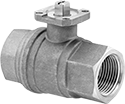
On/Off Valve Bodies


Automatically or manually start and stop flow in your line with these valve bodies, which attach to your actuator. They have a full port, so they don’t restrict flow. All meet standard ISO 5211 mounting dimensions. Use valve stem adapters to mount to valve actuators with a larger stem opening.
316 stainless steel valve bodies have excellent corrosion resistance.
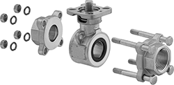
Three-piece valve bodies are easy to maintain because you can take them apart without removing them from your line.
Flow coefficient (Cv) is the amount of water (in gallons per minute) at 60° F that will flow through a fully open valve with a difference of 1 psi between the inlet and the outlet.
Overall | |||||||||||||||
|---|---|---|---|---|---|---|---|---|---|---|---|---|---|---|---|
| Pipe Size | Flow Coefficient (Cv) | Max. Pressure | Max Steam Pressure | Pressure Drop | Temp Range, °F | Actuator Mounting Pattern | Stem Size, mm | Lg. | Wd. | Ht. | Port Type | Max. Torque, in.-lbs. | For Valve Manufacturer Model Number | Each | |
Brass Body—One Piece Construction | |||||||||||||||
NPT Female | |||||||||||||||
| 1/2 | 32.3 | 600 psi @ 100 ° F | Not Rated | Pressure Drop Assisted | -4° to 350° | F03 | 9 | 2 9/16" | 1 1/16" | 2 3/16" | Full | 25 | EA1D64D39-001, EA2R64D39-001 | 0000000 | 000000 |
| 3/4 | 69.3 | 600 psi @ 100 ° F | Not Rated | Pressure Drop Assisted | -4° to 350° | F03 | 9 | 2 15/16" | 1 1/4" | 2 11/16" | Full | 30 | EA1D64E39-001, EA2R64E39-001 | 0000000 | 00000 |
| 1 | 115.5 | 600 psi @ 100 ° F | Not Rated | Pressure Drop Assisted | -4° to 350° | F03 | 9 | 3 9/16" | 1 5/8" | 3" | Full | 60 | EA1D64F39-001, EA2R64F39-001 | 0000000 | 00000 |
| 1 1/4 | 179.1 | 600 psi @ 100 ° F | Not Rated | Pressure Drop Assisted | -4° to 350° | F05 | 14 | 4 1/16" | 1 15/16" | 4 1/16" | Full | 100 | EA3D64G39-001 | 0000000 | 000000 |
| 1 1/2 | 283.1 | 600 psi @ 100 ° F | Not Rated | Pressure Drop Assisted | -4° to 350° | F05 | 14 | 4 9/16" | 2 3/16" | 4 1/2" | Full | 220 | EA3D64H39-001, EA3R64H39-001 | 0000000 | 000000 |
| 2 | 335 | 600 psi @ 100 ° F | Not Rated | Pressure Drop Assisted | -4° to 350° | F05 | 14 | 5 5/16" | 2 3/4" | 5 3/16" | Full | 260 | EA3D64I39-001, EA3R64I39-001 | 0000000 | 000000 |
316 Stainless Steel Body—Three Piece Construction | |||||||||||||||
NPT Female | |||||||||||||||
| 1/2 | 15 | 1500 psi @ 100 ° F | 150 psi @ 212 ° F | Pressure Drop Assisted | -20° to 450° | F03, F04 | 9 | 2 5/8" | 1 13/16" | 1 15/16" | Full | 50 | AS7002MC, AS7012MC | 00000000 | 00000 |
| 3/4 | 35 | 1500 psi @ 100 ° F | 150 psi @ 212 ° F | Pressure Drop Assisted | -20° to 450° | F03, F04 | 9 | 3" | 1" | 2 3/16" | Full | 70 | AS7003MC, AS7013MC | 000000 | 00000 |
| 1 | 60 | 1500 psi @ 100 ° F | 150 psi @ 212 ° F | Pressure Drop Assisted | -20° to 450° | F04, F05 | 11 | 3 3/8" | 2 3/16" | 2 11/16" | Full | 100 | AS7004MC, AS7014MC | 000000 | 000000 |
| 1 1/2 | 138 | 1250 psi @ 100 ° F | 150 psi @ 212 ° F | Pressure Drop Assisted | -20° to 450° | F05, F07 | 14 | 4 11/16" | 3 3/32" | 3 7/8" | Full | 390 | AS7006MC, AS7016MC | 000000 | 000000 |
| 2 | 270 | 1000 psi @ 100 ° F | 150 psi @ 212 ° F | Pressure Drop Assisted | -20° to 450° | F05, F07 | 14 | 5 1/8" | 3 3/4" | 4 1/8" | Full | 480 | AS7007MC, AS7017MC | 000000 | 000000 |
Flow-Adjustment Valve Bodies

Attach these valve bodies to your actuator to automatically or manually control flow in your line. Also known as V-ball valve bodies, they have a V-cut opening that gradually increases flow as you open the valve. They don’t restrict flow because they have a full port. Made from 316 stainless steel, they have excellent corrosion resistance. All meet standard ISO 5211 mounting dimensions. Use valve stem adapters to mount to valve actuators with a larger stem opening.
Flow coefficient (Cv) is the amount of water (in gallons per minute) at 60° F that will flow through a fully open valve with a difference of 1 psi between the inlet and the outlet.
For technical drawings and 3-D models, click on a part number.
Overall | ||||||||||||||
|---|---|---|---|---|---|---|---|---|---|---|---|---|---|---|
| Pipe Size | Flow Coefficient (Cv) | Max. Pressure | Max. Steam Pressure | Temp. Range, °F | Actuator Mounting Pattern | Stem Size, mm | Lg. | Wd. | Ht. | Port Type | Max. Torque, in.-lbs. | Specifications Met | Each | |
316 Stainless Steel Body | ||||||||||||||
NPT Female | ||||||||||||||
| 1/2 | 10.8 | 1000 psi @ 100° F | 150 psi @ 365° F | 0° to 365° | F03 | 9 | 2 5/8" | 1 1/8" | 2 5/16" | Full | 53 | NSF/ANSI 61 | 0000000 | 0000000 |
| 3/4 | 19.8 | 1000 psi @ 100° F | 150 psi @ 365° F | 0° to 365° | F03 | 9 | 3 1/16" | 1 5/8" | 2 1/2" | Full | 53 | NSF/ANSI 61 | 0000000 | 000000 |
| 1 | 26.9 | 1000 psi @ 100° F | 150 psi @ 365° F | 0° to 365° | F03 | 9 | 3 9/16" | 2" | 3 1/8" | Full | 53 | NSF/ANSI 61 | 0000000 | 000000 |
| 1 1/2 | 61.5 | 1000 psi @ 100° F | 150 psi @ 365° F | 0° to 365° | F05 | 11 | 4 3/8" | 3" | 4 7/16" | Full | 150 | NSF/ANSI 61 | 0000000 | 000000 |
| 2 | 101.1 | 1000 psi @ 100° F | 150 psi @ 365° F | 0° to 365° | F05 | 11 | 5 5/16" | 3 13/16" | 5 3/16" | Full | 150 | NSF/ANSI 61 | 0000000 | 000000 |
Universal Air Actuators for Flow-Control Valves
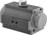
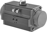
Attach these actuators to manual ball valves, butterfly valves, and plug valves with an ISO 5211 hole pattern to automatically start and stop flow with compressed air.
You must control the air to the actuator using either an electric pilot valve (not included) or a manual on/off valve (not included). Use valve stem adapters to mount actuators to smaller ISO 5211 valve stems.
Single-acting actuators only require air pressure when actuated; they automatically spring closed when the air turns off.
Double-acting actuators require air pressure to open and close.
Pilot valves control the air to the actuator.
Limit switches change the position of the visual dome indicator and send an electrical signal to trigger alarms or other equipment when the actuator opens or closes the valve. The indicator displays green when the valve is open and red when the valve is closed. Switches attach to the top of the actuator with the included mounting bracket. All meet NEMA 4X for protection from washdowns, splashing water, corrosive liquid, and dust.
For technical drawings and 3-D models, click on a part number.

Air Connection | |||||||||||||||
|---|---|---|---|---|---|---|---|---|---|---|---|---|---|---|---|
| Torque @ Pressure | Spring Close Torque | Hole Pattern | Actuator Mounting Pattern | For Stem Size, mm | Housing Material | Pipe Size | Gender | Thread Type | Air Pressure Range, psi | Temp. Range, °F | Lg. | Wd. | Ht. | Each | |
| 83 in.-lbs. @ 80 psi | 71in.-lbs. | ISO 5211 | F04 | 11 | Aluminum | 1/8 | Female | NPT | 40 to 115 | 32° to 175° | 6 1/2" | 2 11/16" | 3 5/8" | 00000000 | 0000000 |
| 160 in.-lbs. @ 80 psi | 114in.-lbs. | ISO 5211 | F05, F07 | 14 | Aluminum | 1/8 | Female | NPT | 40 to 150 | 0° to 175° | 7 5/8" | 3 3/8" | 4 1/4" | 00000000 | 000000 |
| 282 in.-lbs. @ 80 psi | 215in.-lbs. | ISO 5211 | F05, F07, F10 | 19 | Aluminum | 1/4 | Female | NPT | 40 to 115 | 32° to 175° | 9 5/16" | 4 3/16" | 5 1/16" | 00000000 | 000000 |

Air Connection | ||||||||||||||
|---|---|---|---|---|---|---|---|---|---|---|---|---|---|---|
| Torque @ Pressure | Hole Pattern | Actuator Mounting Pattern | For Stem Size, mm | Housing Material | Pipe Size | Gender | Thread Type | Air Pressure Range, psi | Temp. Range, °F | Lg. | Wd. | Ht. | Each | |
| 187 in.-lbs. @ 80 psi | ISO 5211 | F04 | 11 | Aluminum | 1/8 | Female | NPT | 40 to 150 | 0° to 175° | 6 1/2" | 2 11/16" | 3 5/8" | 00000000 | 0000000 |
| 327 in.-lbs. @ 80 psi | ISO 5211 | F05, F07 | 14 | Aluminum | 1/8 | Female | NPT | 40 to 115 | 32° to 175° | 7 5/8" | 3 3/8" | 4 1/4" | 00000000 | 000000 |
| 703 in.-lbs. @ 80 psi | ISO 5211 | F05, F07, F10 | 19 | Aluminum | 1/4 | Female | NPT | 40 to 115 | 32° to 175° | 9 5/16" | 4 3/16" | 5 1/16" | 00000000 | 000000 |
| 1,431 in.-lbs. @ 80 psi | ISO 5211 | F07, F10 | 19 | Aluminum | 1/4 | Female | NPT | 40 to 115 | 32° to 175° | 11 1/2" | 4 9/16" | 6 1/16" | 00000000 | 000000 |
Motor-Driven Valve Actuators

Use electricity to start and stop flow to valves automatically. They adhere to standard ISO 5211 dimensions for mounting to valves. Use valve stem adapters to mount actuators to smaller ISO 5211 valve stems.
To prevent electrical burnout from excessive and unexpected loads, these actuators have a torque limiter. They also have a manual override, so you can continue to operate the actuator during power outages. These actuators have single pole, double throw (SPDT) auxiliary switches, which allow you to connect them to temperature-monitoring equipment, programmable logic controllers (PLCs), or conveyor sirens. A flow indicator on the top of the actuator shows whether the valve is open or closed. When the valve is actuated, an internal heater will automatically turn on to prevent motor damage from condensation buildup.
Fail-in-place actuators will remain in their current position if power is lost.
Fail-closed actuators have a battery that will switch the actuator to the closed position if power is lost, protecting downstream equipment from excessive pressure.
Nylon actuators resist cleaners and other chemicals better than aluminum actuators. IP and NEMA rated, they protect against dust and washdowns. IP67-rated actuators also keep out water when submerged.
Aluminum actuators stand up to impact better than nylon actuators. They are IP and NEMA rated, so they protect against dust, washdowns, and have the highest rating for submersion.
For technical drawings and 3-D models, click on a part number.
| Torque, in.-lbs. | Actuation Time, sec. | Hole Pattern | Actuator Mounting Pattern | For Stem Size, mm | Housing Material | Frequency, Hz | Wire Connection Type | Temp. Range, °F | Lg. | Wd. | Ht. | Environmental Rating | Each | |
100-240V AC—Fail in Place | ||||||||||||||
|---|---|---|---|---|---|---|---|---|---|---|---|---|---|---|
| 133 | 10 | ISO 5211 | F03, F04 | 11 | Nylon Plastic | 50/60 | Screw Terminals | 0° to 130° | 6 3/8" | 4 13/16" | 5 9/16" | IP65, NEMA 4 | 0000000 | 0000000 |
| 150 | 9 | ISO 5211 | F03, F05 | 11 | Aluminum | 50/60 | Screw Terminals | 0° to 130° | 6 1/8" | 5 3/8" | 7" | IP68, NEMA 4X | 0000000 | 000000 |
| 530 | 9 | ISO 5211 | F05, F07 | 14 | Nylon Plastic | 50/60 | Screw Terminals | 0° to 130° | 8 7/16" | 7 1/4" | 8 7/16" | IP67, NEMA 4X | 0000000 | 000000 |
| 530 | 9 | ISO 5211 | F07, F10 | 14 | Aluminum | 50/60 | Screw Terminals | 0° to 130° | 7 3/4" | 6 15/16" | 8 5/8" | IP68, NEMA 4X | 0000000 | 000000 |
| 1,680 | 27 | ISO 5211 | F07, F10 | 17 | Nylon Plastic | 50/60 | Screw Terminals | 0° to 130° | 9 5/16" | 8 5/16" | 9 1/8" | IP67, NEMA 4X | 0000000 | 000000 |
| 1,680 | 27 | ISO 5211 | F07, F10 | 17 | Aluminum | 50/60 | Screw Terminals | 0° to 130° | 10 5/8" | 10 7/16" | 12 5/16" | IP68, NEMA 4X | 0000000 | 00000000 |
100-240V AC—Fail Closed | ||||||||||||||
| 150 | 9 | ISO 5211 | F03, F05 | 11 | Aluminum | 50/60 | Screw Terminals | 0° to 130° | 6 1/8" | 5 3/8" | 7" | IP68, NEMA 4X | 0000000 | 00000000 |
| 530 | 9 | ISO 5211 | F07, F10 | 14 | Aluminum | 50/60 | Screw Terminals | 0° to 130° | 7 3/4" | 6 15/16" | 8 5/8" | IP68, NEMA 4X | 0000000 | 00000000 |
| 1,680 | 27 | ISO 5211 | F07, F10 | 17 | Aluminum | 50/60 | Screw Terminals | 0° to 130° | 10 5/8" | 10 7/16" | 12 5/16" | IP68, NEMA 4X | 0000000 | 00000000 |
24V AC, 24V DC—Fail in Place | ||||||||||||||
| 133 | 10 | ISO 5211 | F03, F04 | 11 | Nylon Plastic | 50/60 | Screw Terminals | 0° to 130° | 6 3/8" | 4 13/16" | 5 9/16" | IP65, NEMA 4 | 0000000 | 000000 |
| 150 | 9 | ISO 5211 | F03, F05 | 11 | Aluminum | 50/60 | Screw Terminals | 0° to 130° | 6 1/8" | 5 3/8" | 7" | IP68, NEMA 4X | 0000000 | 000000 |
| 530 | 9 | ISO 5211 | F05, F07 | 14 | Nylon Plastic | 50/60 | Screw Terminals | 0° to 130° | 8 7/16" | 7 1/4" | 8 7/16" | IP67, NEMA 4X | 0000000 | 000000 |
| 530 | 9 | ISO 5211 | F07, F10 | 14 | Aluminum | 50/60 | Screw Terminals | 0° to 130° | 7 3/4" | 6 15/16" | 8 5/8" | IP68, NEMA 4X | 0000000 | 000000 |
| 1,680 | 27 | ISO 5211 | F07, F10 | 17 | Nylon Plastic | 50/60 | Screw Terminals | 0° to 130° | 9 5/16" | 8 5/16" | 9 1/8" | IP67, NEMA 4X | 0000000 | 000000 |
| 1,680 | 27 | ISO 5211 | F07, F10 | 17 | Aluminum | 50/60 | Screw Terminals | 0° to 130° | 10 5/8" | 10 7/16" | 12 5/16" | IP68, NEMA 4X | 0000000 | 00000000 |
24V AC, 24V DC—Fail Closed | ||||||||||||||
| 150 | 9 | ISO 5211 | F03, F05 | 11 | Aluminum | 50/60 | Screw Terminals | 0° to 130° | 6 1/8" | 5 3/8" | 7" | IP68, NEMA 4X | 0000000 | 000000 |
| 530 | 9 | ISO 5211 | F07, F10 | 14 | Aluminum | 50/60 | Screw Terminals | 0° to 130° | 7 3/4" | 6 15/16" | 8 5/8" | IP68, NEMA 4X | 0000000 | 00000000 |
| 1,680 | 27 | ISO 5211 | F07, F10 | 17 | Aluminum | 50/60 | Screw Terminals | 0° to 130° | 10 5/8" | 10 7/16" | 12 5/16" | IP68, NEMA 4X | 0000000 | 00000000 |
Motor-Driven Flow-Adjustment Valve Actuators

Automatically start, stop, and adjust flow through valves. These actuators receive analog signals from a programmable logic controller (PLC) to regulate flow by controlling how far the valve opens and closes. They adhere to standard ISO 5211 dimensions for mounting to valves. Use valve stem adapters to mount actuators to smaller ISO 5211 valve stems.
To prevent electrical burnout from excessive and unexpected loads, these actuators have a torque limiter. They also have a manual override, so you can continue to operate the actuator during power outages. If power is lost, the actuator will remain in its current position. This is known as fail in place. They also have single pole, double throw (SPDT) auxiliary switches, which allow you to connect these actuators to temperature-monitoring equipment, PLCs, or conveyor sirens. A flow indicator on the top of the actuator shows whether the valve is open or closed. To prevent motor damage from condensation buildup, an internal heater will automatically turn on when the valve is actuated.
Rated IP68 and NEMA 4X, these actuators protect against dust, submersion, and washdown.
For technical drawings and 3-D models, click on a part number.
Input Signal | |||||||||||||||
|---|---|---|---|---|---|---|---|---|---|---|---|---|---|---|---|
| Torque, in.-lbs. | Actuation Time, sec. | Hole Pattern | Actuator Mounting Pattern | For Stem Size, mm | Housing Material | Frequency, Hz | Wire Connection Type | Temp. Range, °F | Current | Voltage | Lg. | Wd. | Ht. | Each | |
100-240V AC—Fail in Place | |||||||||||||||
| 150 | 9 | ISO 5211 | F03, F05 | 11 | Aluminum | 50/60 | Screw Terminals | 0° to 130° | 4mA-20mA | 0V DC-10V DC | 6 1/8" | 5 3/8" | 7" | 0000000 | 0000000 |
| 530 | 9 | ISO 5211 | F07, F10 | 14 | Aluminum | 50/60 | Screw Terminals | 0° to 130° | 4mA-20mA | 0V DC-10V DC | 7 3/4" | 6 15/16" | 8 5/8" | 0000000 | 00000000 |
| 1,680 | 27 | ISO 5211 | F07, F10 | 17 | Aluminum | 50/60 | Screw Terminals | 0° to 130° | 4mA-20mA | 0V DC-10V DC | 10 5/8" | 10 7/16" | 12 5/16" | 0000000 | 00000000 |
24V AC, 24V DC—Fail in Place | |||||||||||||||
| 150 | 9 | ISO 5211 | F03, F05 | 11 | Aluminum | 50/60 | Screw Terminals | 0° to 130° | 4mA-20mA | 0V DC-10V DC | 6 1/8" | 5 3/8" | 7" | 0000000 | 000000 |
| 530 | 9 | ISO 5211 | F07, F10 | 14 | Aluminum | 50/60 | Screw Terminals | 0° to 130° | 4mA-20mA | 0V DC-10V DC | 7 3/4" | 6 15/16" | 8 5/8" | 0000000 | 00000000 |
| 1,680 | 27 | ISO 5211 | F07, F10 | 17 | Aluminum | 50/60 | Screw Terminals | 0° to 130° | 4mA-20mA | 0V DC-10V DC | 10 5/8" | 10 7/16" | 12 5/16" | 0000000 | 00000000 |


