


Filter by
For Use With
Set Pressure
Body Material
Valve Function
Maximum Inlet Pressure
Maximum Temperature
Airflow Capacity
Inlet CGA Number
Minimum Temperature
Diaphragm Material
Relief Port Thread Type
Relief Port
U.S.–Mexico–Canada Agreement (USMCA) Qualifying
DFARS Specialty Metals
Export Control Classification Number (ECCN)
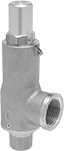
ASME-Code Fast-Acting Pressure-Relief Valves for Cryogenic Fluids
NPT Male Inlet and NPT Female Relief Port
 |
Inlet | Relief | ||||||||||||||||||||||||||||||||||||||||||||||||||||||||||||||||||||||||||||||||||||||||||||||||||
|---|---|---|---|---|---|---|---|---|---|---|---|---|---|---|---|---|---|---|---|---|---|---|---|---|---|---|---|---|---|---|---|---|---|---|---|---|---|---|---|---|---|---|---|---|---|---|---|---|---|---|---|---|---|---|---|---|---|---|---|---|---|---|---|---|---|---|---|---|---|---|---|---|---|---|---|---|---|---|---|---|---|---|---|---|---|---|---|---|---|---|---|---|---|---|---|---|---|---|---|
Pipe Size | Location | Max. Pressure, psi | Port Pipe Size | Port Location | Shape | Overall Ht. | For Use With | Temp. Range, ° F | Valve Type | Certification | Choose a Set Pressure, psi | Each | |||||||||||||||||||||||||||||||||||||||||||||||||||||||||||||||||||||||||||||||||||||||
Brass Body—Brass Seal | |||||||||||||||||||||||||||||||||||||||||||||||||||||||||||||||||||||||||||||||||||||||||||||||||||
| 1/2 | Bottom | 600 | 3/4 | Side | 90° Elbow | 6 9/16" | Argon, Carbon Dioxide, Helium, Hydrogen, Methane, Nitrogen, Oxygen | -320 to 150 | Pop Safety | ASME BPVC.VIII | 20, 30, 40, 50, 60, 70, 80, 90, 100, 110, 120, 130, 140, 150, 160, 170, 180, 190, 200, 210, 220, 230, 240, 250, 260, 270, 280, 290, 300 | 8089K12 | 0000000 | ||||||||||||||||||||||||||||||||||||||||||||||||||||||||||||||||||||||||||||||||||||||
| 3/4 | Bottom | 600 | 1 | Side | 90° Elbow | 6 9/16" | Argon, Carbon Dioxide, Helium, Hydrogen, Methane, Nitrogen, Oxygen | -320 to 150 | Pop Safety | ASME BPVC.VIII | 20, 30, 40, 50, 60, 70, 80, 90, 100, 110, 120, 130, 140, 150, 160, 170, 180, 190, 200, 210, 220, 230, 240, 250, 260, 270, 280, 290, 300 | 8089K14 | 000000 | ||||||||||||||||||||||||||||||||||||||||||||||||||||||||||||||||||||||||||||||||||||||
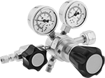
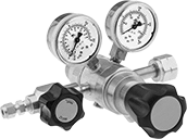
High-Purity Tank-Mount Pressure-Regulating Valves for Fuel Gases
 |
Single Stage |
 |
Two Stage |
Designed to reduce contaminants in high-purity applications using hydrogen and methane gas, these valves have a stainless steel and brass body with a smooth finish to reduce dust collection and internal components designed to protect the seal and diaphragm from contamination. They’re often used in research sample systems, emission monitoring systems, and chromatography. Valves automatically reduce a high inlet pressure from compressed gas tanks to a lower, stable outlet pressure. All have Compressed Gas Association (CGA) numbered inlet fittings for secure connections to compressed gas tanks. Choose a valve with the same CGA number as your tank and other system components. Outlet fittings are Swagelok® for a leak-free seal around hard metal tubing in high-pressure lines. Also known as instrumentation fittings, Swagelok® fittings are compatible with Parker A-Lok, Gyrolok, Bilok, and Tylok fittings. Valves come with a gauge to monitor outlet pressure and a gauge to monitor inlet pressure from the tank.
Choose a valve with a maximum outlet pressure that’s approximately twice your application’s normal operating pressure. Your operating pressure should never exceed 75% of the valve’s maximum outlet pressure.
Single Stage—Single-stage valves reduce pressure in one step, which causes the outlet pressure to fluctuate slightly as you empty the tank. They’re best for applications where a constant outlet pressure isn’t critical.
Two Stage—Two-stage valves progressively reduce pressure over two steps for more consistent outlet pressure at all times. They’re often used in applications that require a constant outlet pressure regardless of the tank level.
Inlet | Outlet | ||||||||||||||||||||||||||||||||||||||||||||||||||||||||||||||||||||||||||||||||||||||||||||||||||
|---|---|---|---|---|---|---|---|---|---|---|---|---|---|---|---|---|---|---|---|---|---|---|---|---|---|---|---|---|---|---|---|---|---|---|---|---|---|---|---|---|---|---|---|---|---|---|---|---|---|---|---|---|---|---|---|---|---|---|---|---|---|---|---|---|---|---|---|---|---|---|---|---|---|---|---|---|---|---|---|---|---|---|---|---|---|---|---|---|---|---|---|---|---|---|---|---|---|---|---|
CGA No. | Location | Thread Direction | Pressure Gauge Reading Range, psi | No. of Stages | For Tube OD | Location | Pressure Range, psi | Pressure Adjustment Method | For Use With | Temp. Range, ° F | Each | ||||||||||||||||||||||||||||||||||||||||||||||||||||||||||||||||||||||||||||||||||||||||
NGO Female Inlet × Swagelok® Female Outlet | |||||||||||||||||||||||||||||||||||||||||||||||||||||||||||||||||||||||||||||||||||||||||||||||||||
Brass Body/Stainless Steel Body—316 Stainless Steel Diaphragm and PTFE Seal with Relief Valve | |||||||||||||||||||||||||||||||||||||||||||||||||||||||||||||||||||||||||||||||||||||||||||||||||||
| 350 | Side | Left Hand | 0 to 4,000 | Single | 1/4" | Side | 0 to 15 | Knob | Hydrogen, Methane | -20 to 120 | 7951A17 | 0000000 | |||||||||||||||||||||||||||||||||||||||||||||||||||||||||||||||||||||||||||||||||||||||
| 350 | Side | Left Hand | 0 to 4,000 | Single | 1/4" | Side | 0 to 125 | Knob | Hydrogen, Methane | -20 to 120 | 7951A19 | 000000 | |||||||||||||||||||||||||||||||||||||||||||||||||||||||||||||||||||||||||||||||||||||||
| 350 | Side | Left Hand | 0 to 4,000 | Two | 1/4" | Side | 0 to 15 | Knob | Hydrogen, Methane | -20 to 120 | 7951A27 | 000000 | |||||||||||||||||||||||||||||||||||||||||||||||||||||||||||||||||||||||||||||||||||||||
| 350 | Side | Left Hand | 0 to 4,000 | Two | 1/4" | Side | 0 to 125 | Knob | Hydrogen, Methane | -20 to 120 | 7951A29 | 000000 | |||||||||||||||||||||||||||||||||||||||||||||||||||||||||||||||||||||||||||||||||||||||
| 350 | Side | Left Hand | 0 to 4,000 | Two | 1/4" | Side | 0 to 500 | Knob | Hydrogen, Methane | -20 to 120 | 7951A71 | 000000 | |||||||||||||||||||||||||||||||||||||||||||||||||||||||||||||||||||||||||||||||||||||||
Tank-Mount Pressure-Regulating Valves for Fuel Gases
Two Stage
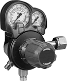 |
Male Outlet × Female Inlet Two-Stage Valve With Knob |
Two-stage valves progressively reduce pressure over two steps for more consistent outlet pressure at all times. They’re often used in applications that require a constant outlet pressure regardless of the tank level.
Brass Body—Valves with a brass body have a longer service life than valves with a brass and steel body.
Stainless Steel Diaphragm—Valves with a stainless steel diaphragm can withstand harsh environments.
Inlet | Outlet | Material | |||||||||||||||||||||||||||||||||||||||||||||||||||||||||||||||||||||||||||||||||||||||||||||||||
|---|---|---|---|---|---|---|---|---|---|---|---|---|---|---|---|---|---|---|---|---|---|---|---|---|---|---|---|---|---|---|---|---|---|---|---|---|---|---|---|---|---|---|---|---|---|---|---|---|---|---|---|---|---|---|---|---|---|---|---|---|---|---|---|---|---|---|---|---|---|---|---|---|---|---|---|---|---|---|---|---|---|---|---|---|---|---|---|---|---|---|---|---|---|---|---|---|---|---|---|
CGA No. | Location | Thread Direction | Pressure Gauge Reading Range, psi | Thread Size | Location | Thread Direction | Pressure Range, psi | Pressure Adjustment Method | Body | Seal | Diaphragm | Temp. Range, ° F | Each | ||||||||||||||||||||||||||||||||||||||||||||||||||||||||||||||||||||||||||||||||||||||
For Hydrogen and Methane | |||||||||||||||||||||||||||||||||||||||||||||||||||||||||||||||||||||||||||||||||||||||||||||||||||
UNF Male Outlet × NGO Female Inlet | |||||||||||||||||||||||||||||||||||||||||||||||||||||||||||||||||||||||||||||||||||||||||||||||||||
| 350 | Side | Left Hand | 0 to 4,000 | 9/16"-18 | Side | Left Hand | 0 to 80 | Knob | Brass | Neoprene | Stainless Steel | -20 to 120 | 7897A35 | 0000000 | |||||||||||||||||||||||||||||||||||||||||||||||||||||||||||||||||||||||||||||||||||||
