Filter by
Contact Point Type
Diameter
Length
Dial Indicator Size
Display Type
Indicator Type
Distance Measured
Measuring Increments
DFARS Specialty Metals
Export Control Classification Number (ECCN)
Body Material
Dial Indicator Type
Mounting Stem Diameter
Contact Points for Plunger Variance Indicators
Radius Contact Points
Dia. | Lg. | Mounting Thread Size | For Dial Indicator Size | Each | |||||||||||||||||||||||||||||||||||||||||||||||||||||||||||||||||||||||||||||||||||||||||||||||
|---|---|---|---|---|---|---|---|---|---|---|---|---|---|---|---|---|---|---|---|---|---|---|---|---|---|---|---|---|---|---|---|---|---|---|---|---|---|---|---|---|---|---|---|---|---|---|---|---|---|---|---|---|---|---|---|---|---|---|---|---|---|---|---|---|---|---|---|---|---|---|---|---|---|---|---|---|---|---|---|---|---|---|---|---|---|---|---|---|---|---|---|---|---|---|---|---|---|---|---|
Steel | |||||||||||||||||||||||||||||||||||||||||||||||||||||||||||||||||||||||||||||||||||||||||||||||||||
| 3/16" | 1/4" | 4-48 | AGD Group 0, AGD Group 1, AGD Group 2, AGD Group 3, AGD Group 4 | 000000000 | 00000 | ||||||||||||||||||||||||||||||||||||||||||||||||||||||||||||||||||||||||||||||||||||||||||||||
| 3/16" | 1/2" | 4-48 | AGD Group 0, AGD Group 1, AGD Group 2, AGD Group 3, AGD Group 4 | 000000000 | 0000 | ||||||||||||||||||||||||||||||||||||||||||||||||||||||||||||||||||||||||||||||||||||||||||||||
| 3/16" | 3/4" | 4-48 | AGD Group 0, AGD Group 1, AGD Group 2, AGD Group 3, AGD Group 4 | 000000000 | 0000 | ||||||||||||||||||||||||||||||||||||||||||||||||||||||||||||||||||||||||||||||||||||||||||||||
| 3/16" | 1" | 4-48 | AGD Group 0, AGD Group 1, AGD Group 2, AGD Group 3, AGD Group 4 | 000000000 | 0000 | ||||||||||||||||||||||||||||||||||||||||||||||||||||||||||||||||||||||||||||||||||||||||||||||
| 3/16" | 2" | 4-48 | AGD Group 0, AGD Group 1, AGD Group 2, AGD Group 3, AGD Group 4 | 000000000 | 0000 | ||||||||||||||||||||||||||||||||||||||||||||||||||||||||||||||||||||||||||||||||||||||||||||||
| 3/16" | 3" | 4-48 | AGD Group 0, AGD Group 1, AGD Group 2, AGD Group 3, AGD Group 4 | 000000000 | 0000 | ||||||||||||||||||||||||||||||||||||||||||||||||||||||||||||||||||||||||||||||||||||||||||||||
| 3/16" | 4" | 4-48 | AGD Group 0, AGD Group 1, AGD Group 2, AGD Group 3, AGD Group 4 | 000000000 | 0000 | ||||||||||||||||||||||||||||||||||||||||||||||||||||||||||||||||||||||||||||||||||||||||||||||
Stainless Steel | |||||||||||||||||||||||||||||||||||||||||||||||||||||||||||||||||||||||||||||||||||||||||||||||||||
| 7/32" | 1/4" | 4-48 | AGD Group 0, AGD Group 1, AGD Group 2, AGD Group 3, AGD Group 4 | 000000000 | 0000 | ||||||||||||||||||||||||||||||||||||||||||||||||||||||||||||||||||||||||||||||||||||||||||||||
| 7/32" | 13/32" | 4-48 | AGD Group 0, AGD Group 1, AGD Group 2, AGD Group 3, AGD Group 4 | 000000000 | 0000 | ||||||||||||||||||||||||||||||||||||||||||||||||||||||||||||||||||||||||||||||||||||||||||||||
| 7/32" | 5/8" | 4-48 | AGD Group 0, AGD Group 1, AGD Group 2, AGD Group 3, AGD Group 4 | 000000000 | 0000 | ||||||||||||||||||||||||||||||||||||||||||||||||||||||||||||||||||||||||||||||||||||||||||||||
| 7/32" | 13/16" | 4-48 | AGD Group 0, AGD Group 1, AGD Group 2, AGD Group 3, AGD Group 4 | 000000000 | 0000 | ||||||||||||||||||||||||||||||||||||||||||||||||||||||||||||||||||||||||||||||||||||||||||||||
Shock-Absorbing Radius Contact Points
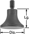
Button Contact Points
Dia. | Lg. | Mounting Thread Size | For Dial Indicator Size | Each | |||||||||||||||||||||||||||||||||||||||||||||||||||||||||||||||||||||||||||||||||||||||||||||||
|---|---|---|---|---|---|---|---|---|---|---|---|---|---|---|---|---|---|---|---|---|---|---|---|---|---|---|---|---|---|---|---|---|---|---|---|---|---|---|---|---|---|---|---|---|---|---|---|---|---|---|---|---|---|---|---|---|---|---|---|---|---|---|---|---|---|---|---|---|---|---|---|---|---|---|---|---|---|---|---|---|---|---|---|---|---|---|---|---|---|---|---|---|---|---|---|---|---|---|---|
Stainless Steel | |||||||||||||||||||||||||||||||||||||||||||||||||||||||||||||||||||||||||||||||||||||||||||||||||||
| 3/8" | 1/8" | 4-48 | AGD Group 0, AGD Group 1, AGD Group 2, AGD Group 3, AGD Group 4 | 000000000 | 00000 | ||||||||||||||||||||||||||||||||||||||||||||||||||||||||||||||||||||||||||||||||||||||||||||||
| 3/8" | 0.3" | M2.5 × 0.45 mm | AGD Group 0, AGD Group 1, AGD Group 2, AGD Group 3, AGD Group 4 | 000000000 | 0000 | ||||||||||||||||||||||||||||||||||||||||||||||||||||||||||||||||||||||||||||||||||||||||||||||
| 1/2" | 0.16" | 4-48 | AGD Group 0, AGD Group 1, AGD Group 2, AGD Group 3, AGD Group 4 | 000000000 | 0000 | ||||||||||||||||||||||||||||||||||||||||||||||||||||||||||||||||||||||||||||||||||||||||||||||
| 1/2" | 0.355" | M2.5 × 0.45 mm | AGD Group 0, AGD Group 1, AGD Group 2, AGD Group 3, AGD Group 4 | 000000000 | 00000 | ||||||||||||||||||||||||||||||||||||||||||||||||||||||||||||||||||||||||||||||||||||||||||||||
| 3/4" | 1/8" | 4-48 | AGD Group 0, AGD Group 1, AGD Group 2, AGD Group 3, AGD Group 4 | 000000000 | 00000 | ||||||||||||||||||||||||||||||||||||||||||||||||||||||||||||||||||||||||||||||||||||||||||||||
| 3/4" | 0.41" | M2.5 × 0.45 mm | AGD Group 0, AGD Group 1, AGD Group 2, AGD Group 3, AGD Group 4 | 000000000 | 00000 | ||||||||||||||||||||||||||||||||||||||||||||||||||||||||||||||||||||||||||||||||||||||||||||||
Ball Contact Points
Dia., mm | Lg. | Precision Ball Grade | Sphericity Tolerance | Mounting Thread Size | Body Material | For Dial Indicator Size | Each | ||||||||||||||||||||||||||||||||||||||||||||||||||||||||||||||||||||||||||||||||||||||||||||
|---|---|---|---|---|---|---|---|---|---|---|---|---|---|---|---|---|---|---|---|---|---|---|---|---|---|---|---|---|---|---|---|---|---|---|---|---|---|---|---|---|---|---|---|---|---|---|---|---|---|---|---|---|---|---|---|---|---|---|---|---|---|---|---|---|---|---|---|---|---|---|---|---|---|---|---|---|---|---|---|---|---|---|---|---|---|---|---|---|---|---|---|---|---|---|---|---|---|---|---|
Carbide | |||||||||||||||||||||||||||||||||||||||||||||||||||||||||||||||||||||||||||||||||||||||||||||||||||
| 3 | 1/4" | 25 | -0.000025" to 0.000025" | 4-48 | Stainless Steel | AGD Group 0, AGD Group 1, AGD Group 2, AGD Group 3, AGD Group 4 | 0000000 | 000000 | |||||||||||||||||||||||||||||||||||||||||||||||||||||||||||||||||||||||||||||||||||||||||||
| 3 | 1/4" | 25 | -0.000025" to 0.000025" | M2.5 × 0.45 mm | Stainless Steel | AGD Group 0, AGD Group 1, AGD Group 2, AGD Group 3, AGD Group 4 | 0000000 | 00000 | |||||||||||||||||||||||||||||||||||||||||||||||||||||||||||||||||||||||||||||||||||||||||||
| 3 | 1/2" | 25 | -0.000025" to 0.000025" | 4-48 | Stainless Steel | AGD Group 0, AGD Group 1, AGD Group 2, AGD Group 3, AGD Group 4 | 0000000 | 00000 | |||||||||||||||||||||||||||||||||||||||||||||||||||||||||||||||||||||||||||||||||||||||||||
| 4 | 1/4" | 25 | -0.000025" to 0.000025" | 4-48 | Stainless Steel | AGD Group 0, AGD Group 1, AGD Group 2, AGD Group 3, AGD Group 4 | 0000000 | 00000 | |||||||||||||||||||||||||||||||||||||||||||||||||||||||||||||||||||||||||||||||||||||||||||
| 4 | 1/2" | 25 | -0.000025" to 0.000025" | 4-48 | Stainless Steel | AGD Group 0, AGD Group 1, AGD Group 2, AGD Group 3, AGD Group 4 | 0000000 | 00000 | |||||||||||||||||||||||||||||||||||||||||||||||||||||||||||||||||||||||||||||||||||||||||||
| 4 | 3/4" | 25 | -0.000025" to 0.000025" | 4-48 | Stainless Steel | AGD Group 0, AGD Group 1, AGD Group 2, AGD Group 3, AGD Group 4 | 0000000 | 00000 | |||||||||||||||||||||||||||||||||||||||||||||||||||||||||||||||||||||||||||||||||||||||||||
Ruby | |||||||||||||||||||||||||||||||||||||||||||||||||||||||||||||||||||||||||||||||||||||||||||||||||||
| 3 | 1/4" | 25 | -0.000025" to 0.000025" | 4-48 | Stainless Steel | AGD Group 0, AGD Group 1, AGD Group 2, AGD Group 3, AGD Group 4 | 0000000 | 00000 | |||||||||||||||||||||||||||||||||||||||||||||||||||||||||||||||||||||||||||||||||||||||||||
| 3 | 1/4" | 25 | -0.000025" to 0.000025" | M2.5 × 0.45 mm | Stainless Steel | AGD Group 0, AGD Group 1, AGD Group 2, AGD Group 3, AGD Group 4 | 0000000 | 00000 | |||||||||||||||||||||||||||||||||||||||||||||||||||||||||||||||||||||||||||||||||||||||||||
| 3 | 1/2" | 25 | -0.000025" to 0.000025" | 4-48 | Stainless Steel | AGD Group 0, AGD Group 1, AGD Group 2, AGD Group 3, AGD Group 4 | 0000000 | 00000 | |||||||||||||||||||||||||||||||||||||||||||||||||||||||||||||||||||||||||||||||||||||||||||
| 4 | 1/4" | 25 | -0.000025" to 0.000025" | 4-48 | Stainless Steel | AGD Group 0, AGD Group 1, AGD Group 2, AGD Group 3, AGD Group 4 | 0000000 | 00000 | |||||||||||||||||||||||||||||||||||||||||||||||||||||||||||||||||||||||||||||||||||||||||||
| 4 | 1/2" | 25 | -0.000025" to 0.000025" | 4-48 | Stainless Steel | AGD Group 0, AGD Group 1, AGD Group 2, AGD Group 3, AGD Group 4 | 0000000 | 00000 | |||||||||||||||||||||||||||||||||||||||||||||||||||||||||||||||||||||||||||||||||||||||||||
| 4 | 3/4" | 25 | -0.000025" to 0.000025" | 4-48 | Stainless Steel | AGD Group 0, AGD Group 1, AGD Group 2, AGD Group 3, AGD Group 4 | 0000000 | 00000 | |||||||||||||||||||||||||||||||||||||||||||||||||||||||||||||||||||||||||||||||||||||||||||
Wide-Ball Contact Points
Dia. | Lg. | Precision Ball Grade | Sphericity Tolerance | Mounting Thread Size | Body Material | For Dial Indicator Size | Each | ||||||||||||||||||||||||||||||||||||||||||||||||||||||||||||||||||||||||||||||||||||||||||||
|---|---|---|---|---|---|---|---|---|---|---|---|---|---|---|---|---|---|---|---|---|---|---|---|---|---|---|---|---|---|---|---|---|---|---|---|---|---|---|---|---|---|---|---|---|---|---|---|---|---|---|---|---|---|---|---|---|---|---|---|---|---|---|---|---|---|---|---|---|---|---|---|---|---|---|---|---|---|---|---|---|---|---|---|---|---|---|---|---|---|---|---|---|---|---|---|---|---|---|---|
Chrome-Plated Steel | |||||||||||||||||||||||||||||||||||||||||||||||||||||||||||||||||||||||||||||||||||||||||||||||||||
| 0.031" | 0.6" | 25 | -0.000025" to 0.000025" | 4-48 | Stainless Steel | AGD Group 0, AGD Group 1, AGD Group 2, AGD Group 3, AGD Group 4 | 00000000 | 000000 | |||||||||||||||||||||||||||||||||||||||||||||||||||||||||||||||||||||||||||||||||||||||||||
| 0.046" | 0.71" | 25 | -0.000025" to 0.000025" | 4-48 | Stainless Steel | AGD Group 0, AGD Group 1, AGD Group 2, AGD Group 3, AGD Group 4 | 00000000 | 00000 | |||||||||||||||||||||||||||||||||||||||||||||||||||||||||||||||||||||||||||||||||||||||||||
| 0.062" | 0.71" | 25 | -0.000025" to 0.000025" | 4-48 | Stainless Steel | AGD Group 0, AGD Group 1, AGD Group 2, AGD Group 3, AGD Group 4 | 00000000 | 00000 | |||||||||||||||||||||||||||||||||||||||||||||||||||||||||||||||||||||||||||||||||||||||||||
| 0.078" | 0.83" | 25 | -0.000025" to 0.000025" | 4-48 | Stainless Steel | AGD Group 0, AGD Group 1, AGD Group 2, AGD Group 3, AGD Group 4 | 00000000 | 00000 | |||||||||||||||||||||||||||||||||||||||||||||||||||||||||||||||||||||||||||||||||||||||||||
| 0.093" | 0.83" | 25 | -0.000025" to 0.000025" | 4-48 | Stainless Steel | AGD Group 0, AGD Group 1, AGD Group 2, AGD Group 3, AGD Group 4 | 00000000 | 00000 | |||||||||||||||||||||||||||||||||||||||||||||||||||||||||||||||||||||||||||||||||||||||||||
| 1/8" | 0.8" | 25 | -0.000025" to 0.000025" | 4-48 | Stainless Steel | AGD Group 0, AGD Group 1, AGD Group 2, AGD Group 3, AGD Group 4 | 00000000 | 00000 | |||||||||||||||||||||||||||||||||||||||||||||||||||||||||||||||||||||||||||||||||||||||||||
| 0.156" | 0.8" | 25 | -0.000025" to 0.000025" | 4-48 | Stainless Steel | AGD Group 0, AGD Group 1, AGD Group 2, AGD Group 3, AGD Group 4 | 00000000 | 00000 | |||||||||||||||||||||||||||||||||||||||||||||||||||||||||||||||||||||||||||||||||||||||||||
| 0.187" | 3/8" | 25 | -0.000025" to 0.000025" | 4-48 | Stainless Steel | AGD Group 0, AGD Group 1, AGD Group 2, AGD Group 3, AGD Group 4 | 00000000 | 00000 | |||||||||||||||||||||||||||||||||||||||||||||||||||||||||||||||||||||||||||||||||||||||||||
| 0.218" | 3/8" | 25 | -0.000025" to 0.000025" | 4-48 | Stainless Steel | AGD Group 0, AGD Group 1, AGD Group 2, AGD Group 3, AGD Group 4 | 00000000 | 00000 | |||||||||||||||||||||||||||||||||||||||||||||||||||||||||||||||||||||||||||||||||||||||||||
| 1/4" | 1/4" | 25 | -0.000025" to 0.000025" | 4-48 | Stainless Steel | AGD Group 0, AGD Group 1, AGD Group 2, AGD Group 3, AGD Group 4 | 00000000 | 00000 | |||||||||||||||||||||||||||||||||||||||||||||||||||||||||||||||||||||||||||||||||||||||||||
| 0.281" | 1/4" | 25 | -0.000025" to 0.000025" | 4-48 | Stainless Steel | AGD Group 0, AGD Group 1, AGD Group 2, AGD Group 3, AGD Group 4 | 00000000 | 00000 | |||||||||||||||||||||||||||||||||||||||||||||||||||||||||||||||||||||||||||||||||||||||||||
| 0.312" | 1/4" | 25 | -0.000025" to 0.000025" | 4-48 | Stainless Steel | AGD Group 0, AGD Group 1, AGD Group 2, AGD Group 3, AGD Group 4 | 00000000 | 00000 | |||||||||||||||||||||||||||||||||||||||||||||||||||||||||||||||||||||||||||||||||||||||||||
| 0.343" | 1/4" | 25 | -0.000025" to 0.000025" | 4-48 | Stainless Steel | AGD Group 0, AGD Group 1, AGD Group 2, AGD Group 3, AGD Group 4 | 00000000 | 00000 | |||||||||||||||||||||||||||||||||||||||||||||||||||||||||||||||||||||||||||||||||||||||||||
| 3/8" | 1/4" | 25 | -0.000025" to 0.000025" | 4-48 | Stainless Steel | AGD Group 0, AGD Group 1, AGD Group 2, AGD Group 3, AGD Group 4 | 00000000 | 00000 | |||||||||||||||||||||||||||||||||||||||||||||||||||||||||||||||||||||||||||||||||||||||||||
| 0.437" | 1/4" | 25 | -0.000025" to 0.000025" | 4-48 | Stainless Steel | AGD Group 0, AGD Group 1, AGD Group 2, AGD Group 3, AGD Group 4 | 00000000 | 00000 | |||||||||||||||||||||||||||||||||||||||||||||||||||||||||||||||||||||||||||||||||||||||||||
| 1/2" | 1/4" | 25 | -0.000025" to 0.000025" | 4-48 | Stainless Steel | AGD Group 0, AGD Group 1, AGD Group 2, AGD Group 3, AGD Group 4 | 00000000 | 00000 | |||||||||||||||||||||||||||||||||||||||||||||||||||||||||||||||||||||||||||||||||||||||||||
| 0.562" | 1/4" | 25 | -0.000025" to 0.000025" | 4-48 | Stainless Steel | AGD Group 0, AGD Group 1, AGD Group 2, AGD Group 3, AGD Group 4 | 00000000 | 00000 | |||||||||||||||||||||||||||||||||||||||||||||||||||||||||||||||||||||||||||||||||||||||||||
Flat Contact Points
Dia. | Lg. | Mounting Thread Size | For Dial Indicator Size | Each | |||||||||||||||||||||||||||||||||||||||||||||||||||||||||||||||||||||||||||||||||||||||||||||||
|---|---|---|---|---|---|---|---|---|---|---|---|---|---|---|---|---|---|---|---|---|---|---|---|---|---|---|---|---|---|---|---|---|---|---|---|---|---|---|---|---|---|---|---|---|---|---|---|---|---|---|---|---|---|---|---|---|---|---|---|---|---|---|---|---|---|---|---|---|---|---|---|---|---|---|---|---|---|---|---|---|---|---|---|---|---|---|---|---|---|---|---|---|---|---|---|---|---|---|---|
Steel | |||||||||||||||||||||||||||||||||||||||||||||||||||||||||||||||||||||||||||||||||||||||||||||||||||
| 3/16" | 1/4" | 4-48 | AGD Group 0, AGD Group 1, AGD Group 2, AGD Group 3, AGD Group 4 | 000000000 | 00000 | ||||||||||||||||||||||||||||||||||||||||||||||||||||||||||||||||||||||||||||||||||||||||||||||
| 3/16" | 1/2" | 4-48 | AGD Group 0, AGD Group 1, AGD Group 2, AGD Group 3, AGD Group 4 | 000000000 | 00000 | ||||||||||||||||||||||||||||||||||||||||||||||||||||||||||||||||||||||||||||||||||||||||||||||
| 3/16" | 3/4" | 4-48 | AGD Group 0, AGD Group 1, AGD Group 2, AGD Group 3, AGD Group 4 | 000000000 | 00000 | ||||||||||||||||||||||||||||||||||||||||||||||||||||||||||||||||||||||||||||||||||||||||||||||
| 3/16" | 1" | 4-48 | AGD Group 0, AGD Group 1, AGD Group 2, AGD Group 3, AGD Group 4 | 000000000 | 00000 | ||||||||||||||||||||||||||||||||||||||||||||||||||||||||||||||||||||||||||||||||||||||||||||||
Stainless Steel | |||||||||||||||||||||||||||||||||||||||||||||||||||||||||||||||||||||||||||||||||||||||||||||||||||
| 7/32" | 3/8" | 4-48 | AGD Group 0, AGD Group 1, AGD Group 2, AGD Group 3, AGD Group 4 | 000000000 | 0000 | ||||||||||||||||||||||||||||||||||||||||||||||||||||||||||||||||||||||||||||||||||||||||||||||
| 7/32" | 3/8" | M2.5 × 0.45 mm | AGD Group 0, AGD Group 1, AGD Group 2, AGD Group 3, AGD Group 4 | 000000000 | 0000 | ||||||||||||||||||||||||||||||||||||||||||||||||||||||||||||||||||||||||||||||||||||||||||||||
| 7/32" | 5/8" | 4-48 | AGD Group 0, AGD Group 1, AGD Group 2, AGD Group 3, AGD Group 4 | 000000000 | 0000 | ||||||||||||||||||||||||||||||||||||||||||||||||||||||||||||||||||||||||||||||||||||||||||||||
| 7/32" | 1 1/4" | 4-48 | AGD Group 0, AGD Group 1, AGD Group 2, AGD Group 3, AGD Group 4 | 000000000 | 0000 | ||||||||||||||||||||||||||||||||||||||||||||||||||||||||||||||||||||||||||||||||||||||||||||||
Wide-Flat Contact Point Variances
Style | Dia. | Lg. | Mounting Thread Size | For Dial Indicator Size | Each | ||||||||||||||||||||||||||||||||||||||||||||||||||||||||||||||||||||||||||||||||||||||||||||||
|---|---|---|---|---|---|---|---|---|---|---|---|---|---|---|---|---|---|---|---|---|---|---|---|---|---|---|---|---|---|---|---|---|---|---|---|---|---|---|---|---|---|---|---|---|---|---|---|---|---|---|---|---|---|---|---|---|---|---|---|---|---|---|---|---|---|---|---|---|---|---|---|---|---|---|---|---|---|---|---|---|---|---|---|---|---|---|---|---|---|---|---|---|---|---|---|---|---|---|---|
Steel | |||||||||||||||||||||||||||||||||||||||||||||||||||||||||||||||||||||||||||||||||||||||||||||||||||
| A | 1/4" | 3/32" | 4-48 | AGD Group 0, AGD Group 1, AGD Group 2, AGD Group 3, AGD Group 4 | 000000000 | 00000 | |||||||||||||||||||||||||||||||||||||||||||||||||||||||||||||||||||||||||||||||||||||||||||||
| A | 3/8" | 3/32" | 4-48 | AGD Group 0, AGD Group 1, AGD Group 2, AGD Group 3, AGD Group 4 | 000000000 | 00000 | |||||||||||||||||||||||||||||||||||||||||||||||||||||||||||||||||||||||||||||||||||||||||||||
| A | 1/2" | 3/32" | 4-48 | AGD Group 0, AGD Group 1, AGD Group 2, AGD Group 3, AGD Group 4 | 000000000 | 00000 | |||||||||||||||||||||||||||||||||||||||||||||||||||||||||||||||||||||||||||||||||||||||||||||
| A | 5/8" | 3/32" | 4-48 | AGD Group 0, AGD Group 1, AGD Group 2, AGD Group 3, AGD Group 4 | 000000000 | 00000 | |||||||||||||||||||||||||||||||||||||||||||||||||||||||||||||||||||||||||||||||||||||||||||||
| B | 2" | 1/8" | 4-48 | AGD Group 0, AGD Group 1, AGD Group 2, AGD Group 3, AGD Group 4 | 000000000 | 00000 | |||||||||||||||||||||||||||||||||||||||||||||||||||||||||||||||||||||||||||||||||||||||||||||
Stainless Steel | |||||||||||||||||||||||||||||||||||||||||||||||||||||||||||||||||||||||||||||||||||||||||||||||||||
| B | 1/4" | 0.112" | M2.5 × 0.45 mm | AGD Group 0, AGD Group 1, AGD Group 2, AGD Group 3, AGD Group 4 | 000000000 | 0000 | |||||||||||||||||||||||||||||||||||||||||||||||||||||||||||||||||||||||||||||||||||||||||||||
| B | 3/8" | 0.093" | M2.5 × 0.45 mm | AGD Group 0, AGD Group 1, AGD Group 2, AGD Group 3, AGD Group 4 | 000000000 | 0000 | |||||||||||||||||||||||||||||||||||||||||||||||||||||||||||||||||||||||||||||||||||||||||||||
| B | 1/2" | 0.1" | M2.5 × 0.45 mm | AGD Group 0, AGD Group 1, AGD Group 2, AGD Group 3, AGD Group 4 | 000000000 | 0000 | |||||||||||||||||||||||||||||||||||||||||||||||||||||||||||||||||||||||||||||||||||||||||||||
| B | 5/8" | 0.1" | M2.5 × 0.45 mm | AGD Group 0, AGD Group 1, AGD Group 2, AGD Group 3, AGD Group 4 | 000000000 | 00000 | |||||||||||||||||||||||||||||||||||||||||||||||||||||||||||||||||||||||||||||||||||||||||||||
| B | 3/4" | 0.1" | 4-48 | AGD Group 0, AGD Group 1, AGD Group 2, AGD Group 3, AGD Group 4 | 000000000 | 00000 | |||||||||||||||||||||||||||||||||||||||||||||||||||||||||||||||||||||||||||||||||||||||||||||
| B | 3/4" | 0.1" | M2.5 × 0.45 mm | AGD Group 0, AGD Group 1, AGD Group 2, AGD Group 3, AGD Group 4 | 000000000 | 00000 | |||||||||||||||||||||||||||||||||||||||||||||||||||||||||||||||||||||||||||||||||||||||||||||
| B | 1" | 1/8" | 4-48 | AGD Group 0, AGD Group 1, AGD Group 2, AGD Group 3, AGD Group 4 | 000000000 | 00000 | |||||||||||||||||||||||||||||||||||||||||||||||||||||||||||||||||||||||||||||||||||||||||||||
| B | 1" | 1/8" | M2.5 × 0.45 mm | AGD Group 0, AGD Group 1, AGD Group 2, AGD Group 3, AGD Group 4 | 000000000 | 00000 | |||||||||||||||||||||||||||||||||||||||||||||||||||||||||||||||||||||||||||||||||||||||||||||
Bell Contact Points
Dia. | Lg. | Mounting Thread Size | For Dial Indicator Size | Each | |||||||||||||||||||||||||||||||||||||||||||||||||||||||||||||||||||||||||||||||||||||||||||||||
|---|---|---|---|---|---|---|---|---|---|---|---|---|---|---|---|---|---|---|---|---|---|---|---|---|---|---|---|---|---|---|---|---|---|---|---|---|---|---|---|---|---|---|---|---|---|---|---|---|---|---|---|---|---|---|---|---|---|---|---|---|---|---|---|---|---|---|---|---|---|---|---|---|---|---|---|---|---|---|---|---|---|---|---|---|---|---|---|---|---|---|---|---|---|---|---|---|---|---|---|
Steel | |||||||||||||||||||||||||||||||||||||||||||||||||||||||||||||||||||||||||||||||||||||||||||||||||||
| 3/8" | 3/8" | 4-48 | AGD Group 0, AGD Group 1, AGD Group 2, AGD Group 3, AGD Group 4 | 000000000 | 000000 | ||||||||||||||||||||||||||||||||||||||||||||||||||||||||||||||||||||||||||||||||||||||||||||||
| 1/2" | 3/8" | 4-48 | AGD Group 0, AGD Group 1, AGD Group 2, AGD Group 3, AGD Group 4 | 000000000 | 00000 | ||||||||||||||||||||||||||||||||||||||||||||||||||||||||||||||||||||||||||||||||||||||||||||||
Black-Oxide Steel | |||||||||||||||||||||||||||||||||||||||||||||||||||||||||||||||||||||||||||||||||||||||||||||||||||
| 3/8" | 0.38" | M2.5 × 0.45 mm | AGD Group 0, AGD Group 1, AGD Group 2, AGD Group 3, AGD Group 4 | 000000000 | 00000 | ||||||||||||||||||||||||||||||||||||||||||||||||||||||||||||||||||||||||||||||||||||||||||||||
| 1/2" | 0.38" | M2.5 × 0.45 mm | AGD Group 0, AGD Group 1, AGD Group 2, AGD Group 3, AGD Group 4 | 000000000 | 00000 | ||||||||||||||||||||||||||||||||||||||||||||||||||||||||||||||||||||||||||||||||||||||||||||||
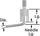
Needle Contact Points
Dia. | Lg. | Needle Lg. | Mounting Thread Size | Body Material | For Dial Indicator Size | Each | |||||||||||||||||||||||||||||||||||||||||||||||||||||||||||||||||||||||||||||||||||||||||||||
|---|---|---|---|---|---|---|---|---|---|---|---|---|---|---|---|---|---|---|---|---|---|---|---|---|---|---|---|---|---|---|---|---|---|---|---|---|---|---|---|---|---|---|---|---|---|---|---|---|---|---|---|---|---|---|---|---|---|---|---|---|---|---|---|---|---|---|---|---|---|---|---|---|---|---|---|---|---|---|---|---|---|---|---|---|---|---|---|---|---|---|---|---|---|---|---|---|---|---|---|
Carbide | |||||||||||||||||||||||||||||||||||||||||||||||||||||||||||||||||||||||||||||||||||||||||||||||||||
| 0.015" | 0.4" | 0.12" | 4-48 | Stainless Steel | AGD Group 0, AGD Group 1, AGD Group 2, AGD Group 3, AGD Group 4 | 000000000 | 000000 | ||||||||||||||||||||||||||||||||||||||||||||||||||||||||||||||||||||||||||||||||||||||||||||
| 0.015" | 0.4" | 0.12" | M2.5 × 0.45 mm | Stainless Steel | AGD Group 0, AGD Group 1, AGD Group 2, AGD Group 3, AGD Group 4 | 000000000 | 00000 | ||||||||||||||||||||||||||||||||||||||||||||||||||||||||||||||||||||||||||||||||||||||||||||
| 0.031" | 0.4" | 0.12" | 4-48 | Stainless Steel | AGD Group 0, AGD Group 1, AGD Group 2, AGD Group 3, AGD Group 4 | 000000000 | 00000 | ||||||||||||||||||||||||||||||||||||||||||||||||||||||||||||||||||||||||||||||||||||||||||||
| 0.062" | 0.8" | 1/2" | 4-48 | Stainless Steel | AGD Group 0, AGD Group 1, AGD Group 2, AGD Group 3, AGD Group 4 | 000000000 | 00000 | ||||||||||||||||||||||||||||||||||||||||||||||||||||||||||||||||||||||||||||||||||||||||||||
| 0.062" | 1.3" | 1" | 4-48 | Stainless Steel | AGD Group 0, AGD Group 1, AGD Group 2, AGD Group 3, AGD Group 4 | 000000000 | 00000 | ||||||||||||||||||||||||||||||||||||||||||||||||||||||||||||||||||||||||||||||||||||||||||||
| 0.062" | 1.3" | 1" | M2.5 × 0.45 mm | Stainless Steel | AGD Group 0, AGD Group 1, AGD Group 2, AGD Group 3, AGD Group 4 | 000000000 | 00000 | ||||||||||||||||||||||||||||||||||||||||||||||||||||||||||||||||||||||||||||||||||||||||||||
| 0.078" | 1.3" | 1" | 4-48 | Stainless Steel | AGD Group 0, AGD Group 1, AGD Group 2, AGD Group 3, AGD Group 4 | 000000000 | 00000 | ||||||||||||||||||||||||||||||||||||||||||||||||||||||||||||||||||||||||||||||||||||||||||||
| 0.078" | 1.3" | 1" | M2.5 × 0.45 mm | Stainless Steel | AGD Group 0, AGD Group 1, AGD Group 2, AGD Group 3, AGD Group 4 | 000000000 | 00000 | ||||||||||||||||||||||||||||||||||||||||||||||||||||||||||||||||||||||||||||||||||||||||||||
Bent Needle Contact Points
Tapered Contact Points
Dia. | Lg. | Mounting Thread Size | For Dial Indicator Size | Each | |||||||||||||||||||||||||||||||||||||||||||||||||||||||||||||||||||||||||||||||||||||||||||||||
|---|---|---|---|---|---|---|---|---|---|---|---|---|---|---|---|---|---|---|---|---|---|---|---|---|---|---|---|---|---|---|---|---|---|---|---|---|---|---|---|---|---|---|---|---|---|---|---|---|---|---|---|---|---|---|---|---|---|---|---|---|---|---|---|---|---|---|---|---|---|---|---|---|---|---|---|---|---|---|---|---|---|---|---|---|---|---|---|---|---|---|---|---|---|---|---|---|---|---|---|
Steel | |||||||||||||||||||||||||||||||||||||||||||||||||||||||||||||||||||||||||||||||||||||||||||||||||||
| 3/16" | 13/32" | 4-48 | AGD Group 0, AGD Group 1, AGD Group 2, AGD Group 3, AGD Group 4 | 000000000 | 00000 | ||||||||||||||||||||||||||||||||||||||||||||||||||||||||||||||||||||||||||||||||||||||||||||||
| 3/16" | 1" | 4-48 | AGD Group 0, AGD Group 1, AGD Group 2, AGD Group 3, AGD Group 4 | 000000000 | 0000 | ||||||||||||||||||||||||||||||||||||||||||||||||||||||||||||||||||||||||||||||||||||||||||||||
| 3/16" | 1 1/2" | 4-48 | AGD Group 0, AGD Group 1, AGD Group 2, AGD Group 3, AGD Group 4 | 000000000 | 00000 | ||||||||||||||||||||||||||||||||||||||||||||||||||||||||||||||||||||||||||||||||||||||||||||||
| 3/16" | 2" | 4-48 | AGD Group 0, AGD Group 1, AGD Group 2, AGD Group 3, AGD Group 4 | 000000000 | 00000 | ||||||||||||||||||||||||||||||||||||||||||||||||||||||||||||||||||||||||||||||||||||||||||||||
Black-Oxide Steel | |||||||||||||||||||||||||||||||||||||||||||||||||||||||||||||||||||||||||||||||||||||||||||||||||||
| 0.19" | 5/8" | M2.5 × 0.45 mm | AGD Group 0, AGD Group 1, AGD Group 2, AGD Group 3, AGD Group 4 | 000000000 | 0000 | ||||||||||||||||||||||||||||||||||||||||||||||||||||||||||||||||||||||||||||||||||||||||||||||
Knife Contact Points
Lg. | Mounting Thread Size | For Dial Indicator Size | Each | ||||||||||||||||||||||||||||||||||||||||||||||||||||||||||||||||||||||||||||||||||||||||||||||||
|---|---|---|---|---|---|---|---|---|---|---|---|---|---|---|---|---|---|---|---|---|---|---|---|---|---|---|---|---|---|---|---|---|---|---|---|---|---|---|---|---|---|---|---|---|---|---|---|---|---|---|---|---|---|---|---|---|---|---|---|---|---|---|---|---|---|---|---|---|---|---|---|---|---|---|---|---|---|---|---|---|---|---|---|---|---|---|---|---|---|---|---|---|---|---|---|---|---|---|---|
Stainless Steel | |||||||||||||||||||||||||||||||||||||||||||||||||||||||||||||||||||||||||||||||||||||||||||||||||||
| 0.6" | 4-48 | AGD Group 0, AGD Group 1, AGD Group 2, AGD Group 3, AGD Group 4 | 000000000 | 000000 | |||||||||||||||||||||||||||||||||||||||||||||||||||||||||||||||||||||||||||||||||||||||||||||||
Roller Contact Points
Dia. | Lg. | Mounting Thread Size | Body Material | For Dial Indicator Size | Each | ||||||||||||||||||||||||||||||||||||||||||||||||||||||||||||||||||||||||||||||||||||||||||||||
|---|---|---|---|---|---|---|---|---|---|---|---|---|---|---|---|---|---|---|---|---|---|---|---|---|---|---|---|---|---|---|---|---|---|---|---|---|---|---|---|---|---|---|---|---|---|---|---|---|---|---|---|---|---|---|---|---|---|---|---|---|---|---|---|---|---|---|---|---|---|---|---|---|---|---|---|---|---|---|---|---|---|---|---|---|---|---|---|---|---|---|---|---|---|---|---|---|---|---|---|
Stainless Steel | |||||||||||||||||||||||||||||||||||||||||||||||||||||||||||||||||||||||||||||||||||||||||||||||||||
| 3/8" | 0.51" | 4-48 | Aluminum | AGD Group 0, AGD Group 1, AGD Group 2, AGD Group 3, AGD Group 4 | 000000000 | 000000 | |||||||||||||||||||||||||||||||||||||||||||||||||||||||||||||||||||||||||||||||||||||||||||||
| 3/8" | 0.54" | M2.5 × 0.45 mm | Aluminum | AGD Group 0, AGD Group 1, AGD Group 2, AGD Group 3, AGD Group 4 | 000000000 | 00000 | |||||||||||||||||||||||||||||||||||||||||||||||||||||||||||||||||||||||||||||||||||||||||||||
| 1/2" | 0.76" | 4-48 | Stainless Steel | AGD Group 0, AGD Group 1, AGD Group 2, AGD Group 3, AGD Group 4 | 000000000 | 00000 | |||||||||||||||||||||||||||||||||||||||||||||||||||||||||||||||||||||||||||||||||||||||||||||
Plunger Variance Indicator Extension Rods
4-48 Male × 4-48 Female Mounting Thread | M2.5 Male × M2.5 Female Mounting Thread | ||||||||||||||||||||||||||||||||||||||||||||||||||||||||||||||||||||||||||||||||||||||||||||||||||
|---|---|---|---|---|---|---|---|---|---|---|---|---|---|---|---|---|---|---|---|---|---|---|---|---|---|---|---|---|---|---|---|---|---|---|---|---|---|---|---|---|---|---|---|---|---|---|---|---|---|---|---|---|---|---|---|---|---|---|---|---|---|---|---|---|---|---|---|---|---|---|---|---|---|---|---|---|---|---|---|---|---|---|---|---|---|---|---|---|---|---|---|---|---|---|---|---|---|---|---|
Lg. | Dia. | For Dial Indicator Size | Each | Each | |||||||||||||||||||||||||||||||||||||||||||||||||||||||||||||||||||||||||||||||||||||||||||||||
Stainless Steel | |||||||||||||||||||||||||||||||||||||||||||||||||||||||||||||||||||||||||||||||||||||||||||||||||||
| 1/2" | 7/32" | AGD Group 0, AGD Group 1, AGD Group 2, AGD Group 3, AGD Group 4 | 000000000 | 00000 | 00000000 | 00000 | |||||||||||||||||||||||||||||||||||||||||||||||||||||||||||||||||||||||||||||||||||||||||||||
| 1" | 7/32" | AGD Group 0, AGD Group 1, AGD Group 2, AGD Group 3, AGD Group 4 | 000000000 | 0000 | 00000000 | 0000 | |||||||||||||||||||||||||||||||||||||||||||||||||||||||||||||||||||||||||||||||||||||||||||||
| 1 1/2" | 7/32" | AGD Group 0, AGD Group 1, AGD Group 2, AGD Group 3, AGD Group 4 | 000000000 | 0000 | 00000000 | 0000 | |||||||||||||||||||||||||||||||||||||||||||||||||||||||||||||||||||||||||||||||||||||||||||||
| 2" | 7/32" | AGD Group 0, AGD Group 1, AGD Group 2, AGD Group 3, AGD Group 4 | 000000000 | 0000 | 00000000 | 0000 | |||||||||||||||||||||||||||||||||||||||||||||||||||||||||||||||||||||||||||||||||||||||||||||
| 2 1/2" | 7/32" | AGD Group 0, AGD Group 1, AGD Group 2, AGD Group 3, AGD Group 4 | 000000000 | 0000 | 00000000 | 0000 | |||||||||||||||||||||||||||||||||||||||||||||||||||||||||||||||||||||||||||||||||||||||||||||
| 3" | 7/32" | AGD Group 0, AGD Group 1, AGD Group 2, AGD Group 3, AGD Group 4 | 000000000 | 0000 | 00000000 | 0000 | |||||||||||||||||||||||||||||||||||||||||||||||||||||||||||||||||||||||||||||||||||||||||||||
| 4" | 7/32" | AGD Group 0, AGD Group 1, AGD Group 2, AGD Group 3, AGD Group 4 | 000000000 | 0000 | 00000000 | 00000 | |||||||||||||||||||||||||||||||||||||||||||||||||||||||||||||||||||||||||||||||||||||||||||||
| 6" | 7/32" | AGD Group 0, AGD Group 1, AGD Group 2, AGD Group 3, AGD Group 4 | 000000000 | 0000 | 00000000 | 00000 | |||||||||||||||||||||||||||||||||||||||||||||||||||||||||||||||||||||||||||||||||||||||||||||
Carbon Steel | |||||||||||||||||||||||||||||||||||||||||||||||||||||||||||||||||||||||||||||||||||||||||||||||||||
| 8" | 3/16" | AGD Group 0, AGD Group 1, AGD Group 2, AGD Group 3, AGD Group 4 | 000000000 | 00000 | ——— | 0 | |||||||||||||||||||||||||||||||||||||||||||||||||||||||||||||||||||||||||||||||||||||||||||||
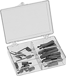
Economy Contact Point Sets for Plunger Variance Indicators
No. of Pieces | Contact Point Type | Includes | For Dial Indicator Size | Mounting Thread Size | Container Type | Each | |||||||||||||||||||||||||||||||||||||||||||||||||||||||||||||||||||||||||||||||||||||||||||||
|---|---|---|---|---|---|---|---|---|---|---|---|---|---|---|---|---|---|---|---|---|---|---|---|---|---|---|---|---|---|---|---|---|---|---|---|---|---|---|---|---|---|---|---|---|---|---|---|---|---|---|---|---|---|---|---|---|---|---|---|---|---|---|---|---|---|---|---|---|---|---|---|---|---|---|---|---|---|---|---|---|---|---|---|---|---|---|---|---|---|---|---|---|---|---|---|---|---|---|---|
Stainless Steel | |||||||||||||||||||||||||||||||||||||||||||||||||||||||||||||||||||||||||||||||||||||||||||||||||||
| 11 | Radius Flat Bent Needle Conical | Two 0.218" to 0.625" Lg. Radius Contact Points Six 0.250" to 1.250" Lg. Flat Contact Points One 0.312” Lg. Bent Needle Contact Point Two 0.625" to 0.750" Lg. Conical Contact Points | AGD Group 0, AGD Group 1, AGD Group 2, AGD Group 3, AGD Group 4 | 4-48 | Case | 00000000 | 000000 | ||||||||||||||||||||||||||||||||||||||||||||||||||||||||||||||||||||||||||||||||||||||||||||
| 22 | Radius Flat Needle Bent Needle Conical | Five 0.225” to 0.825” Lg. Radius Contact Points Nine 0.175” to 1.250” Lg. Flat Contact Points Three 0.935” to 1.35” Lg. Needle Contact Points One 0.312” Lg. Bent Needle Contact Point Four 0.500” to 0.875” Lg. Conical Contact Points | AGD Group 0, AGD Group 1, AGD Group 2, AGD Group 3, AGD Group 4 | 4-48 | Case | 00000000 | 00000 | ||||||||||||||||||||||||||||||||||||||||||||||||||||||||||||||||||||||||||||||||||||||||||||
Mitutoyo Continuous Dial Plunger Variance Indicators with Calibration Certificate
Dial | Contact Point | ||||||||||||||||||||||||||||||||||||||||||||||||||||||||||||||||||||||||||||||||||||||||||||||||||
|---|---|---|---|---|---|---|---|---|---|---|---|---|---|---|---|---|---|---|---|---|---|---|---|---|---|---|---|---|---|---|---|---|---|---|---|---|---|---|---|---|---|---|---|---|---|---|---|---|---|---|---|---|---|---|---|---|---|---|---|---|---|---|---|---|---|---|---|---|---|---|---|---|---|---|---|---|---|---|---|---|---|---|---|---|---|---|---|---|---|---|---|---|---|---|---|---|---|---|---|
Distance Measured | Measuring Increments | Accuracy | Dial Indicator Size | Mounting Stem Dia. | Mounting Lug Hole Dia. | Dia. | Reading Inch | Dia. | Lg. | Mounting Thread Size | Mfr. Model No. | Each | |||||||||||||||||||||||||||||||||||||||||||||||||||||||||||||||||||||||||||||||||||||||
Lug Mount, Stem Mount | |||||||||||||||||||||||||||||||||||||||||||||||||||||||||||||||||||||||||||||||||||||||||||||||||||
Plain Bearing | |||||||||||||||||||||||||||||||||||||||||||||||||||||||||||||||||||||||||||||||||||||||||||||||||||
| 0" to 1.000" | 0.001" | ±0.002" | AGD Group 4 | 3/8" | 1/4" | 3 1/16" | 0-100 | 0.118" | 1.36" | 4-48 | 3416ACAL | 0000000 | 0000000 | ||||||||||||||||||||||||||||||||||||||||||||||||||||||||||||||||||||||||||||||||||||||
Jeweled Bearing | |||||||||||||||||||||||||||||||||||||||||||||||||||||||||||||||||||||||||||||||||||||||||||||||||||
| 0" to 3.000" | 0.001" | ±0.005" | AGD Group 4 | 3/8" | 1/4" | 3 1/16" | 0-100 | 0.118" | 3.35" | 4-48 | 3426A-19CAL | 0000000 | 000000 | ||||||||||||||||||||||||||||||||||||||||||||||||||||||||||||||||||||||||||||||||||||||
| 0" to 3.000" | 0.001" | ±0.005" | AGD Group 4 | 3/8" | 1/4" | 3 5/8" | 0-100 | 0.118" | 3.35" | 4-48 | 4887A-19CAL | 0000000 | 000000 | ||||||||||||||||||||||||||||||||||||||||||||||||||||||||||||||||||||||||||||||||||||||
| 0" to 4.000" | 0.001" | ±0.005" | AGD Group 4 | 3/8" | 1/4" | 3 1/16" | 0-100 | 0.118" | 4.35" | 4-48 | 3428A-19CAL | 0000000 | 000000 | ||||||||||||||||||||||||||||||||||||||||||||||||||||||||||||||||||||||||||||||||||||||
Plunger Variance Indicator Extension Rod Sets
4-48 Male × 4-48 Female Mounting Thread | M2.5 Male × M2.5 Female Mounting Thread | ||||||
|---|---|---|---|---|---|---|---|
For Dial Indicator Size | Material | Includes | Each | Each | |||
| AGD Group 0, AGD Group 1, AGD Group 2, AGD Group 3, AGD Group 4 | Stainless Steel | One 1" Lg., 7/32" Dia. Extension Rod One 2" Lg., 7/32" Dia. Extension Rod One 3" Lg., 7/32" Dia. Extension Rod | 000000000 | 000000 | 00000000 | 000000 | |
90° Angle Contact Point Adapters for Plunger Variance Indicators
For Dial Indicator Size | For Mounting Stem Dia. | Material | Each | ||
|---|---|---|---|---|---|
| AGD Group 0, AGD Group 1, AGD Group 2, AGD Group 3, AGD Group 4 | 3/8" | Steel | 000000000 | 000000 |
Mitutoyo Continuous Dial Plunger Variance Indicators
Dial | Contact Point | ||||||||||||||||||||||||||||||||||||||||||||||||||||||||||||||||||||||||||||||||||||||||||||||||||
|---|---|---|---|---|---|---|---|---|---|---|---|---|---|---|---|---|---|---|---|---|---|---|---|---|---|---|---|---|---|---|---|---|---|---|---|---|---|---|---|---|---|---|---|---|---|---|---|---|---|---|---|---|---|---|---|---|---|---|---|---|---|---|---|---|---|---|---|---|---|---|---|---|---|---|---|---|---|---|---|---|---|---|---|---|---|---|---|---|---|---|---|---|---|---|---|---|---|---|---|
Distance Measured | Measuring Increments | Accuracy | Dial Indicator Size | Mounting Stem Dia. | Mounting Lug Hole Dia. | Dia. | Reading Inch | Dia. | Lg. | Mounting Thread Size | Mfr. Model No. | Each | |||||||||||||||||||||||||||||||||||||||||||||||||||||||||||||||||||||||||||||||||||||||
Lug Mount, Stem Mount | |||||||||||||||||||||||||||||||||||||||||||||||||||||||||||||||||||||||||||||||||||||||||||||||||||
Jeweled Bearing | |||||||||||||||||||||||||||||||||||||||||||||||||||||||||||||||||||||||||||||||||||||||||||||||||||
| 0" to 3.000" | 0.001" | ±0.005" | AGD Group 4 | 3/8" | 1/4" | 3 5/8" | 0-100 | 0.118" | 3.354" | 4-48 | 4887A-19 | 00000000 | 0000000 | ||||||||||||||||||||||||||||||||||||||||||||||||||||||||||||||||||||||||||||||||||||||
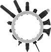
Starrett Contact Point Sets for Plunger Variance Indicators
 |
No. of Pieces | Contact Point Type | Includes | For Dial Indicator Size | Ring Material | Mfr. Model No. | Each | |||||||||||||||||||||||||||||||||||||||||||||||||||||||||||||||||||||||||||||||||||||||||||||
|---|---|---|---|---|---|---|---|---|---|---|---|---|---|---|---|---|---|---|---|---|---|---|---|---|---|---|---|---|---|---|---|---|---|---|---|---|---|---|---|---|---|---|---|---|---|---|---|---|---|---|---|---|---|---|---|---|---|---|---|---|---|---|---|---|---|---|---|---|---|---|---|---|---|---|---|---|---|---|---|---|---|---|---|---|---|---|---|---|---|---|---|---|---|---|---|---|---|---|---|
Steel | |||||||||||||||||||||||||||||||||||||||||||||||||||||||||||||||||||||||||||||||||||||||||||||||||||
| 14 | Radius Shock-Absorbing Radius Button Ball Bell Tapered Conical | One 1/4” Lg. Radius Contact Point One 1/2” Lg. Radius Contact Point One 3/4” Lg. Radius Contact Point One 1” Lg. Radius Contact Point One Shock-Absorbing Radius Contact Point Two Button Contact Points Two Ball Contact Points Two Bell Contact Points One Tapered Contact Point Two Conical Contact Points | AGD Group 0, AGD Group 1, AGD Group 2, AGD Group 3, AGD Group 4 | Aluminum | 25R | 0000000 | 0000000 | ||||||||||||||||||||||||||||||||||||||||||||||||||||||||||||||||||||||||||||||||||||||||||||
Plunger Variance Indicator Lifting Levers
For Dial Indicator Size | Material | Mounting Hardware Included | Each | ||||||||||||||||||||||||||||||||||||||||||||||||||||||||||||||||||||||||||||||||||||||||||||||||
|---|---|---|---|---|---|---|---|---|---|---|---|---|---|---|---|---|---|---|---|---|---|---|---|---|---|---|---|---|---|---|---|---|---|---|---|---|---|---|---|---|---|---|---|---|---|---|---|---|---|---|---|---|---|---|---|---|---|---|---|---|---|---|---|---|---|---|---|---|---|---|---|---|---|---|---|---|---|---|---|---|---|---|---|---|---|---|---|---|---|---|---|---|---|---|---|---|---|---|---|
Plunger Mount | |||||||||||||||||||||||||||||||||||||||||||||||||||||||||||||||||||||||||||||||||||||||||||||||||||
| AGD Group 0, AGD Group 1, AGD Group 2, AGD Group 3, AGD Group 4 | Plastic | No | 0000000 | 00000 | |||||||||||||||||||||||||||||||||||||||||||||||||||||||||||||||||||||||||||||||||||||||||||||||
