About Pressure-Relief Valves
More
Gas Chimney Vents and Fittings
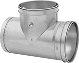
For use with gas-fired equipment, such as boilers and furnaces, these vent pipes and fittings withstand temperatures up to 400° F. Also known as type B gas vents.
To join pipes and connectors, insert a male end into a female end and secure with the included locking band.
For technical drawings and 3-D models, click on a part number.

Galvanized Steel | ||||||||
|---|---|---|---|---|---|---|---|---|
| Chimney Pipe Size | Female ID | Male OD | Gauge | Construction | Inner Wall Material | Specifications Met | Each | |
Female × Female × Male | ||||||||
| 4 | 4" | 4 1/2" | 28 | Double Wall | Aluminum | UL Listed | 0000000 | 000000 |
| 5 | 5" | 5 1/2" | 28 | Double Wall | Aluminum | UL Listed | 0000000 | 00000 |
| 6 | 6" | 6 1/2" | 28 | Double Wall | Aluminum | UL Listed | 0000000 | 00000 |
| 8 | 8" | 9" | 28 | Double Wall | Aluminum | UL Listed | 0000000 | 000000 |
High-Temperature Chimney Vents and Fittings
Built to withstand temperatures up to 1000° F, these vent pipes and fittings are for use with boilers, furnaces, stoves, and other equipment that is fired by gas, oil, wood, or coal.
To join pipes and connectors, twist a male end into a female end and secure with the included locking band.

304 Stainless Steel | |||||||||
|---|---|---|---|---|---|---|---|---|---|
| Chimney Pipe Size | Female ID | Male OD | Gauge | Construction | Insulation Thick. | Includes | Specifications Met | Each | |
Female × Female × Male | |||||||||
| 6 | 6" | 8" | 28 | Double Wall | 1" | Locking Band, Removable Cap | UL Listed | 0000000 | 0000000 |
| 8 | 8" | 10" | 28 | Double Wall | 1" | Locking Band, Removable Cap | UL Listed | 0000000 | 000000 |
| 10 | 10" | 12" | 28 | Double Wall | 1" | Locking Band, Removable Cap | UL Listed | 0000000 | 000000 |
Pressure-Relief Valves with Push-to-Connect Fittings for Air

- For Use With: Air
- Temperature Range: 26° to 255° F
For a low-pressure seal around plastic and soft metal tubing, these valves have push-to-connect fittings. They allow inline flow from the inlet to the outlet during normal conditions and divert flow to the relief port in overpressure conditions. The relief port begins opening at the set pressure and fully opens at about 10% over the set pressure. It begins closing as pressure drops and fully closes when the system pressure is restored below the set pressure. The vented relief port exhausts discharge directly. Set pressure is not adjustable. Valves are color coded based on the set pressure for easy identification.
Inlet | Outlet | ||||||||
|---|---|---|---|---|---|---|---|---|---|
| For Tube OD | Location | Maximum Pressure | For Tube OD | Location | Relief Port Location | Overall Ht. | Choose a Set Pressure, psi | Each | |
Push-to-Connect Female Inlet, Outlet and Relief Vent | |||||||||
Nylon Body—Buna-N Seal | |||||||||
| 1/4" | Side | Not Rated | 1/4" | Side | Top | 1 1/4" | 0000000 | 000000 | |
| 5/16" | Side | Not Rated | 5/16" | Side | Top | 1 5/16" | 0000000 | 00000 | |
| 3/8" | Side | Not Rated | 3/8" | Side | Top | 1 1/2" | 0000000 | 00000 | |
| 1/2" | Side | Not Rated | 1/2" | Side | Top | 1 3/4" | 0000000 | 00000 | |
Adjustable Inline Pressure-Relief Valves for Chemicals

- For Use With: Potassium Sulfate, Sodium Hypochlorite
- Temperature Range: 0° to 140° F
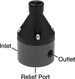
With a three-port design, these valves allow inline flow from the inlet to the outlet during normal conditions and divert flow through the relief port in overpressure conditions. Often used with feed pumps for fertilizers and bleach, they have a PVC body and a PTFE seal for excellent chemical resistance. The relief port begins opening at the set pressure and fully opens at about 10% over the set pressure. It begins closing as pressure drops and fully closes when the system pressure is restored below the set pressure, resuming inline flow from the inlet to the outlet. Adjust the set pressure within the range.
Inlet | Outlet | Relief Port | Set Pressure | ||||||||
|---|---|---|---|---|---|---|---|---|---|---|---|
| Pipe Size | Location | Maximum Pressure, psi | Pipe Size | Location | Pipe Size | Location | Range, psi | Adjustment Method | Overall Ht. | Each | |
NPT Female Inlet, Outlet, and Relief Port | |||||||||||
Dark Gray PVC Body—PTFE Seal | |||||||||||
| 1/4 | Side | 350 | 1/4 | Side | 1/4 | Bottom | 10 to 150 | External Adjustment Screw | 3 17/32" | 00000000 | 0000000 |
| 1/2 | Side | 350 | 1/2 | Side | 1/2 | Bottom | 10 to 250 | External Adjustment Screw | 5 9/16" | 00000000 | 000000 |
| 1 | Side | 350 | 1 | Side | 1 | Bottom | 10 to 250 | External Adjustment Screw | 5 7/8" | 00000000 | 000000 |


