


Filter by


Movement

Weight Capacity
Base Material
Inner Ring Width
Ring Material
Ring Thickness
Ring Height
Load Securement Type
Base Width
Base Length
Export Control Classification Number (ECCN)
DFARS Specialty Metals
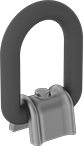
Weld-on-Mount Hoist Rings—For Lifting
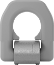 | 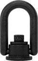 |
180° Pivot | 180° Pivot and 360° Swivel |
 |
180° Pivot |
 |
360° Swivel |
Inside Wd. | Overall Ht. | Vert. Cap., lb. | Specs. Met | Certification | Each | |||
|---|---|---|---|---|---|---|---|---|
180° Pivot | ||||||||
Forged Orange Painted Steel | ||||||||
| 1 1/2" | 3 1/8" | 3,300 | — | CE Marked | 7987N21 | 000000 | ||
| 1 3/4" | 3 9/16" | 5,510 | — | CE Marked | 7987N22 | 00000 | ||
| 2" | 4" | 8,810 | — | CE Marked | 7987N23 | 00000 | ||
| 2 5/8" | 6 3/16" | 22,040 | — | CE Marked | 7987N25 | 000000 | ||
| 2 11/16" | 5 9/16" | 14,770 | — | CE Marked | 7987N24 | 00000 | ||
180° Pivot and 360° Swivel | ||||||||
Forged Black-Oxide Steel | ||||||||
| 2" | 5 1/2" | 5,000 | ASME B30.26 | — | 7987N11 | 000000 | ||
| 3" | 7 5/8" | 10,000 | ASME B30.26 | — | 7987N12 | 000000 | ||
| 4" | 9 1/2" | 24,000 | ASME B30.26 | — | 7987N13 | 000000 | ||
Weld-On Tie-Down Rings
 |  |  |  |
Style A | Style B | Style C | Style D |
Ring | Base | |||||||||||||
|---|---|---|---|---|---|---|---|---|---|---|---|---|---|---|
Style | Wt. Cap., lb. | Inner Wd. | Ht. | Thk. | Style | Lg. | Wd. | Ht. | Thk. | Material | Each | |||
Zinc-Plated Steel | ||||||||||||||
| A | 2,000 | 2 9/16" | 2 11/16" | 3/8" | D-Ring | 2" | 15/16" | — | 1/4" | Low-Carbon Steel | 3028T31 | 00000 | ||
Blue Painted Steel | ||||||||||||||
| A | 6,600 | 1 1/2" | 3 3/16" | 1/2" | D-Ring | 1 3/8" | 1 15/16" | — | — | Alloy Steel | 3028T63 | 00000 | ||
| A | 11,000 | 1 3/4" | 3 7/16" | 9/16" | D-Ring | 1 5/8" | 1 15/16" | — | — | Alloy Steel | 3028T64 | 00000 | ||
| A | 17,600 | 2" | 4 1/16" | 11/16" | D-Ring | 1 13/16" | 2 3/16" | — | — | Alloy Steel | 3028T65 | 000000 | ||
| A | 29,800 | 2 11/16" | 5 11/16" | 15/16" | D-Ring | 2 1/2" | 3 1/16" | — | — | Alloy Steel | 3028T66 | 000000 | ||
| A | 44,100 | 2 3/4" | 6" | 1 1/16" | D-Ring | 2 1/2" | 3 5/8" | — | — | Alloy Steel | 3028T67 | 000000 | ||
| C | 17,600 | 1 7/8" | 3 3/8" | 9/16" | D-Ring | 5 1/4" | 2 5/8" | 1 1/16" | — | Alloy Steel | 3028T61 | 000000 | ||
| C | 29,800 | 2 3/8" | 4 1/16" | 13/16" | D-Ring | 6 11/16" | 3 1/8" | 1 7/16" | — | Alloy Steel | 3028T62 | 000000 | ||
Red Painted Steel | ||||||||||||||
| B | 2,100 | 1 7/16" | 2 9/16" | 0.43" | D-Ring | 1 1/4" | 1 1/4" | — | — | Alloy Steel | 3028T53 | 00000 | ||
| B | 3,500 | 1 5/8" | 3 1/16" | 0.55" | D-Ring | 1 1/2" | 1 1/2" | — | — | Alloy Steel | 3028T54 | 00000 | ||
| B | 7,100 | 1 7/8" | 3 3/4" | 0.71" | D-Ring | 1 3/4" | 1 3/4" | — | — | Alloy Steel | 3028T55 | 00000 | ||
| B | 12,000 | 2 5/8" | 5 3/8" | 0.94" | D-Ring | 2 3/8" | 2 3/8" | — | — | Alloy Steel | 3028T56 | 00000 | ||
| B | 18,100 | 2 13/16" | 5 3/4" | 1.1" | D-Ring | 2 11/16" | 2 9/16" | — | — | Alloy Steel | 3028T57 | 000000 | ||
| B | 34,200 | 4 3/4" | 8 1/8" | 1 1/2" | D-Ring | 3 3/4" | 4 1/4" | — | — | Alloy Steel | 3028T58 | 000000 | ||
Steel | ||||||||||||||
| A | 4,080 | 2 3/8" | 3 1/2" | 1/2" | D-Ring | 2" | 1 5/16" | — | 11/16" | Low-Carbon Steel | 3028T32 | 00000 | ||
| A | 4,080 | 2 1/2" | 5 1/2" | 1/2" | D-Ring | 2" | 1 5/16" | — | 3/8" | Low-Carbon Steel | 3028T72 | 0000 | ||
| A | 6,130 | 3" | 4 1/4" | 5/8" | D-Ring | 2 1/2" | 1 5/8" | — | 3/8" | Low-Carbon Steel | 3028T25 | 00000 | ||
| A | 9,120 | 3" | 4 1/2" | 3/4" | D-Ring | 2 1/4" | 1 5/8" | — | 3/8" | Low-Carbon Steel | 3028T26 | 00000 | ||
| A | 15,500 | 3" | 6" | 1" | D-Ring | 2 1/4" | 2 1/8" | — | 3/8" | Low-Carbon Steel | 3028T27 | 00000 | ||
| D | 15,500 | 3" | 5 1/2" | 1" | Angled-Bend D-Ring | 2 1/4" | 2 1/8" | — | 1/2" | Low-Carbon Steel | 3028T71 | 00000 | ||
316 Stainless Steel | ||||||||||||||
| A | 3,000 | 2 5/16" | 3 5/8" | 1/2" | D-Ring | 2" | 1 3/8" | — | 1/4" | 316 Stainless Steel | 3028T43 | 000000 | ||
| A | 4,500 | 2 15/16" | 4 1/2" | 5/8" | D-Ring | 2 9/16" | 1 3/4" | — | 3/8" | 316 Stainless Steel | 3028T44 | 000000 | ||
| A | 6,500 | 2 15/16" | 4 5/8" | 3/4" | D-Ring | 2 9/16" | 1 7/8" | — | 3/8" | 316 Stainless Steel | 3028T45 | 000000 | ||
| A | 8,500 | 3" | 5 1/8" | 1" | D-Ring | 2 9/16" | 2 1/8" | — | 1/2" | 316 Stainless Steel | 3028T46 | 000000 | ||
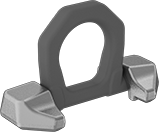
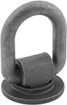
Fixed Weld-On Tie-Down Rings
 |  |
Style A | Style B |
Also known as pad eyes, these rigid rings provide a strong, fixed anchor point on machinery, equipment, and vehicles. Weld them to a surface for a more secure connection than other tie-down rings.
Warning: Never use for lifting applications.
316 Stainless Steel—316 stainless steel rings have excellent resistance to salt water and chemicals.
Style B—Style B rings are curved for mounting to pipe and other round surfaces.
Ring | Base | Each | |||||||||||||
|---|---|---|---|---|---|---|---|---|---|---|---|---|---|---|---|
Style | Wt. Cap. | Inner Wd. | Ht. | Thk. | Style | Dia. | Lg. | Wd. | Material | 1-24 | 25-99 | 100-Up | |||
Steel | |||||||||||||||
| A | Not Rated | 1/4" | 3/4" | 3/16" | Round Ring | 5/8" | — | — | Low-Carbon Steel | 3024T14 | 00000 | 00000 | 00000 | ||
| A | Not Rated | 3/8" | 1" | 1/4" | Round Ring | 7/8" | — | — | Low-Carbon Steel | 3024T16 | 0000 | 0000 | 0000 | ||
| A | Not Rated | 5/8" | 1 5/16" | 1/4" | Round Ring | 1" | — | — | Low-Carbon Steel | 3024T18 | 0000 | 0000 | 0000 | ||
| A | Not Rated | 3/4" | 1 5/8" | 3/8" | Round Ring | 1 1/16" | — | — | Low-Carbon Steel | 3024T22 | 0000 | 0000 | 0000 | ||
| A | Not Rated | 1" | 2 5/16" | 9/16" | Round Ring | 1 7/16" | — | — | Low-Carbon Steel | 3024T23 | 00000 | 00000 | 00000 | ||
| A | Not Rated | 1 3/16" | 2 3/8" | 7/16" | Round Ring | 1 11/16" | — | — | Low-Carbon Steel | 3024T24 | 0000 | 0000 | 0000 | ||
| A | Not Rated | 1 1/4" | 2 3/4" | 11/16" | Round Ring | 1 3/4" | — | — | Low-Carbon Steel | 3024T26 | 00000 | 00000 | 00000 | ||
| B | Not Rated | 5/8" | 7/8" | 1/4" | Round Ring | — | 1 1/8" | 1 1/8" | Alloy Steel | 8892T22 | 00000 | 00000 | 00000 | ||
316 Stainless Steel | |||||||||||||||
| A | Not Rated | 1/2" | 1 1/16" | 3/16" | Round Ring | 3/8" | — | — | 316 Stainless Steel | 8892T9 | 0000 | 0000 | 0000 | ||
| A | Not Rated | 5/8" | 1 5/16" | 1/4" | Round Ring | 9/16" | — | — | 316 Stainless Steel | 8892T11 | 0000 | 0000 | 0000 | ||
| A | Not Rated | 3/4" | 1 9/16" | 5/16" | Round Ring | 5/8" | — | — | 316 Stainless Steel | 8892T12 | 00000 | 0000 | 0000 | ||
| A | Not Rated | 1" | 2" | 3/8" | Round Ring | 7/8" | — | — | 316 Stainless Steel | 8892T14 | 00000 | 00000 | 00000 | ||
| A | Not Rated | 1 1/4" | 2 1/2" | 1/2" | Round Ring | 1" | — | — | 316 Stainless Steel | 8892T16 | 00000 | 00000 | 00000 | ||
| A | Not Rated | 1 1/2" | 3 1/4" | 5/8" | Round Ring | 1 3/8" | — | — | 316 Stainless Steel | 8892T18 | 00000 | 00000 | 00000 | ||
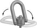
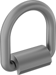
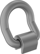
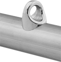
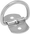
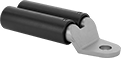
Swiveling Weld-On Tie-Down Rings
 | 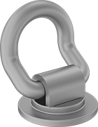 |
Style A | Style B |
Before welding, these rings swivel all the way around to accommodate ties in any direction. Weld them to any surface for a more secure connection than other tie-down rings.
Warning: Never use for lifting applications.
Style B—Style B rings are angled, making it easier to attach bulky ties and straps. They also protect ties and straps from abrasion to prevent them from wearing down over time.
Welding Lug Covers
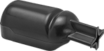 |
For Wire Ga. | Material | For Lug Shape | Each | ||
|---|---|---|---|---|---|
| 6, 4, 2, 1, 1/0, 2/0, 3/0, 4/0 | Vinyl Plastic | Straight | 7828A11 | 00000 |
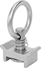
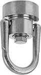
Dimpled Tie-Down Rings
 |  |
Style A | Style B |
Dimples hold the base tight to prevent it from swiveling.
Warning: Never use for lifting applications.
Zinc-Plated Steel—Zinc-plated steel rings have mild corrosion resistance.
316 Stainless Steel—316 stainless steel rings have excellent chemical and corrosion resistance, so they won’t rust in marine environments.
Style B—Style B has loose rings that twist to minimize abrasion on webbing and rope.
Ring | Base | Mounting Holes | Each | |||||||||||||
|---|---|---|---|---|---|---|---|---|---|---|---|---|---|---|---|---|
Style | Wt. Cap., lb. | Inner Wd. | Ht. | Thk. | Style | Lg. | Wd. | Material | Mounting Fasteners Included | No. of | Dia. | 1-49 | 50-Up | |||
Zinc-Plated Steel | ||||||||||||||||
| A | 5,600 | 1 1/8" | 1 3/16" | 1/2" | Round Ring | 2 1/2" | 1 3/4" | Zinc-Plated Steel | No | 1 | 7/16" | 31665T25 | 00000 | 00000 | ||
316 Stainless Steel | ||||||||||||||||
| A | 5,620 | 1 1/8" | 1 3/16" | 1/2" | Round Ring | 2 1/2" | 1 3/4" | 316 Stainless Steel | No | 1 | 7/16" | 31665T31 | 0000 | 0000 | ||
| B | 5,620 | 1 1/8" | 1 3/16" | 1/2" | Round Ring | 2 1/2" | 1 3/4" | 316 Stainless Steel | No | 1 | 7/16" | 31665T33 | 00000 | 00000 | ||
Adhesive-Ready Tie-Down Rings
 |
Large holes in the base allow adhesive to flow through. It's made of 316 stainless steel for excellent resistance to salt water and chemicals.
Warning: Never use for lifting applications.
Ring | Base | |||||||||||
|---|---|---|---|---|---|---|---|---|---|---|---|---|
Wt. Cap. | Inner Wd. | Ht. | Thk. | Style | Lg. | Wd. | Thk. | Material | Each | |||
316 Stainless Steel | ||||||||||||
| Not Rated | 1/2" | 13/16" | 3/16" | Angled-Bend D-Ring | 1 1/4" | 1 1/4" | 1/16" | 316 Stainless Steel | 1963N11 | 00000 | ||
Tie-Down Rings for Quick-Adjust L-Tracks
 | 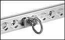 |
Round Rings for 1 Mounting Point |
Wt. Cap., lb. | Inner Ring Wd. | Projection | End Fitting Material | Each | |||
|---|---|---|---|---|---|---|---|
Round Rings for 1 Mounting Point | |||||||
| 1,000 | 1 1/8" | 2" | Zinc-Plated Steel | 39695T51 | 00000 | ||
Hammer-On Welding Lugs
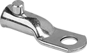 |
Slide these welding lugs onto cable and strike them with your hammer to create a durable connection.
For Wire Ga. | For Screw Size | For Screw Size Decimal Equiv. | For Wire Construction | For Wire Material | Lg. | Wd. | Ht. | Thk. | Terminal Material | Max. Temp. | Max. Voltage | Each | |||
|---|---|---|---|---|---|---|---|---|---|---|---|---|---|---|---|
Straight | |||||||||||||||
1 Hole—For 1 Wire | |||||||||||||||
| 1, 1/0, 2/0 | 1/2" | 0.500" | Stranded | Aluminum, Copper | 2.875" | 1" | 0.75" | 0.15" | Copper | Not Rated | Not Rated | 69575K3 | 00000 | ||
| 3/0, 4/0 | 1/2" | 0.500" | Stranded | Aluminum, Copper | 3.156" | 1.156" | 0.906" | 0.18" | Copper | Not Rated | Not Rated | 69575K4 | 00000 | ||
|
For Wire Ga. | Material | Each | ||
|---|---|---|---|---|
| 6, 4, 2, 1, 1/0, 2/0, 3/0, 4/0 | Vinyl Plastic | 7828A11 | 00000 |
Solder and Compression Welding Lugs
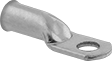 |
Solder these welding lugs in place, or use a crimping tool (not included) for a secure connection.
For Wire Ga. | For Screw Size | For Screw Size Decimal Equiv. | For Wire Construction | For Wire Material | Lg. | Wd. | Ht. | Thk. | Terminal Material | Max. Temp. | Max. Voltage | Each | |||
|---|---|---|---|---|---|---|---|---|---|---|---|---|---|---|---|
Straight | |||||||||||||||
1 Hole—For 1 Wire | |||||||||||||||
| 6, 4, 2 | 1/2" | 0.500" | Stranded | Copper | 2.67" | 0.78" | 0.63" | 0.12" | Copper | Not Rated | 80V AC 80V DC | 7913A1 | 00000 | ||
| 1, 1/0, 2/0 | 1/2" | 0.500" | Stranded | Copper | 2.89" | 1" | 0.768" | 0.15" | Copper | Not Rated | 80V AC 80V DC | 7913A2 | 0000 | ||
| 3/0, 4/0 | 1/2" | 0.500" | Stranded | Copper | 3.15" | 1.17" | 0.89" | 0.16" | Copper | Not Rated | 80V AC 80V DC | 7913A3 | 0000 | ||
| 4/0 | 5/8" | 0.625" | Stranded | Copper | 3.87" | 1.36" | 1.02" | 0.17" | Copper | Not Rated | 80V AC 80V DC | 7913A4 | 00000 | ||
|
For Wire Ga. | Material | Each | ||
|---|---|---|---|---|
| 6, 4, 2, 1, 1/0, 2/0, 3/0, 4/0 | Vinyl Plastic | 7828A11 | 00000 |
Fall-Arrest Anchors
Weld On
 |
Weld-on anchors swivel 360°, so your lanyard turns smoothly with you as you move.
Material | Connection Hardware | D-Ring Movement | Breaking Strength, lbf | Wt. Cap., lb. | Specs. Met | Each | |||
|---|---|---|---|---|---|---|---|---|---|
| Steel | D-Ring | Swivel | 10,000 | 420 | ANSI/ASSP Z359.18, OSHA Compliant 29 CFR 1910.140, OSHA Compliant 29 CFR 1926.502 | 11005T44 | 0000000 | ||
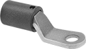
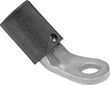
Tie-Down Rings
 |
Shown as Tie-Down (Bracket Not Included) |
 |
Style A |
 |
Style B |
These rings pivot to secure loads in various directions.
Warning: Never use for lifting applications.
Zinc-Plated Steel—Zinc-plated steel rings have mild corrosion resistance.
Ring | Base | Mounting Holes | Each | |||||||||||||||
|---|---|---|---|---|---|---|---|---|---|---|---|---|---|---|---|---|---|---|
Style | Wt. Cap., lb. | Inner Wd. | Ht. | Thk. | Style | Lg. | Wd. | Material | Mounting Fasteners Included | No. of | Dia. | Ctr.-to-Ctr. Lg. | For Mounting Screw Size | 1-99 | 100-Up | |||
Zinc-Plated Steel | ||||||||||||||||||
| A | 1,000 | 1 7/16" | 1 1/2" | 1/4" | D-Ring | 1 5/8" | 1 3/8" | Zinc-Plated Steel | No | 1 | 7/16" | — | 7/16" | 3076T039 | 00000 | 00000 | ||
| E | 1,000 | 1 1/2" | 1 13/16" | 1/4" | D-Ring | 1 9/16" | 1 1/4" | Zinc-Plated Steel | No | 2 | 1/4" | 15/16" | 1/4" | 3076T037 | 0000 | 0000 | ||
| E | 1,500 | 2" | 2 1/8" | 1/4" | D-Ring | 2 1/8" | 1 7/8" | Zinc-Plated Steel | No | 2 | 1/4" | 1 3/8" | 1/4" | 3076T038 | 0000 | 0000 | ||
Black Zinc-Plated Steel | ||||||||||||||||||
| B | 800 | 1 29/32" | 2 1/8" | 1/4" | D-Ring | 1 9/16" | 1 1/2" | Zinc-Plated Steel | No | 1 | 13/32" | — | 3/8" | 33815T52 | 0000 | 0000 | ||
Welding Cable Connectors
Plugs
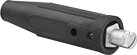 |
Current, amp | Wire Connection | For Wire Ga. | For Cable OD | Housing Connection Method | OD | Lg. | Color | Temp. Range, ° F | Each | ||
|---|---|---|---|---|---|---|---|---|---|---|---|
| 250 | Screw Terminal | 4, 3, 2, 1, 1/0 | 0.2" to 0.5" | Push In | 1.3" | 5.9" | Black | -50 to 350 | 7841A14 | 000000 | |
| 350 | Screw Terminal | 1/0, 2/0 | 0.32" to 0.56" | Push In | 1.4" | 5.9" | Black | -50 to 350 | 7841A16 | 00000 | |
| 500 | Screw Terminal | 3/0, 4/0 | 0.41" to 0.63" | Push In | 1.4" | 5.9" | Black | -50 to 350 | 7841A22 | 00000 |
Sockets
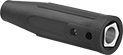 |
Current, amp | Wire Connection | For Wire Ga. | For Cable OD | Housing Connection Method | OD | Lg. | Color | Temp. Range, ° F | Each | ||
|---|---|---|---|---|---|---|---|---|---|---|---|
| 250 | Screw Terminal | 4, 3, 2, 1, 1/0 | 0.2" to 0.5" | Push In | 1.3" | 4.9" | Black | -50 to 350 | 7841A15 | 000000 | |
| 350 | Screw Terminal | 1/0, 2/0 | 0.32" to 0.56" | Push In | 1.4" | 4.9" | Black | -50 to 350 | 7841A21 | 00000 | |
| 500 | Screw Terminal | 3/0, 4/0 | 0.41" to 0.63" | Push In | 1.4" | 4.9" | Black | -50 to 350 | 7841A23 | 00000 |
Solder and Compression Welding Lug Assortments
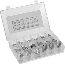 |
Keep a variety of welding lug sizes on hand. Either solder these welding lugs into place, or use a hammer-on crimper (not included) for a secure connection.
No. of Pieces | Includes | For Wire Material | For Wire Construction | Terminal Material | Max. Temp., ° F | Max. Voltage, V DC | Each | |||
|---|---|---|---|---|---|---|---|---|---|---|
1 Hole—For 1 Wire | ||||||||||
| 68 | 6 AWG for 1/4", 5/16" and 3/8" Screws, 4 AWG for 1/4", 5/16", 3/8" and 1/2" Screws, 2 AWG, 1/0-4/0 for 3/8" and 1/2" Screws; Plastic Compartmented Case | Copper | Stranded | Copper | 190 | 48 | 4189N11 | 000000 | ||
Tight-Hold Compression Lugs
These prevent pullout better than other compression lugs, and they give you more options for attaching the wire. To attach with solder, heat the enclosed solder onto your stranded wire. This bonds the wire to the lug for a secure hold and a continuous, ultra-conductive metallic connection. If sharp bends and tugs aren't a concern, you can skip the soldering and use a compression tool to squeeze the barrel tightly and evenly onto the wire. Compression lugs are a step up from set screw lugs when you need a physically strong connection, though set screw lugs attach to even larger wire.
For Wire Ga. | For Screw Size | Lg. | Wd. | Ht. | Thk. | For Wire Construction | For Wire Material | Terminal Material | Max. Temp. | Max. Voltage | Each | |||
|---|---|---|---|---|---|---|---|---|---|---|---|---|---|---|
Solder and Compression Connection | ||||||||||||||
| 8 to 6 | 5/16" | 1.39" | 0.539" | 0.380" | 0.08" | Stranded | Copper | Copper | Not Rated | Not Rated | 7913A41 | 00000 | ||
| 6 to 4 | 5/16" | 1.6" | 0.622" | 0.450" | 0.1" | Stranded | Copper | Copper | Not Rated | Not Rated | 7913A42 | 0000 | ||
Welding Cable Connector Sets
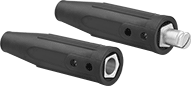 |
Each set includes one plug and one socket. Plugs lock into sockets with a cam action that pulls the two pieces together tightly. The housing resists oil.
Mated Housing | |||||||||||
|---|---|---|---|---|---|---|---|---|---|---|---|
Current, amp | Wire Connection | For Wire Ga. | For Cable OD | Housing Connection Method | Dia. | Lg. | Color | Temp. Range, ° F | Each | ||
| 250 | Screw Terminal | 4, 3, 2, 1, 1/0 | 0.2" to 0.5" | Push In | 1.3" | 9.7" | Black | -50 to 350 | 7841A11 | 000000 | |
| 350 | Screw Terminal | 1/0, 2/0 | 0.32" to 0.56" | Push In | 1.4" | 9.8" | Black | -50 to 350 | 7841A12 | 00000 | |
| 500 | Screw Terminal | 3/0, 4/0 | 0.41" to 0.63" | Push In | 1.4" | 9.8" | Black | -50 to 350 | 7841A13 | 00000 | |
Insulated Set Screw Welding Lugs
 |  |  |
Straight 1 Hole—For 1 Wire | Straight 1 Hole—For 2 Wires | 45° Elbow |
To prevent short-circuiting with nearby wire, a plastic cover insulates the barrel on these welding lugs. Tighten the set screw for a secure connection without crimping.
45° Elbow—45° elbow lugs connect to wire at an angle, so they fit in tight spaces.
For Wire Ga. | For Screw Size | For Screw Size Decimal Equiv. | For Wire Construction | For Wire Material | Lg. | Wd. | Ht. | Thk. | Insulation Color | Insulation Material | Terminal Material | Max. Temp., ° F | Max. Voltage | Each | |||
|---|---|---|---|---|---|---|---|---|---|---|---|---|---|---|---|---|---|
Straight | |||||||||||||||||
1 Hole—For 1 Wire | |||||||||||||||||
| 6, 4, 2, 1, 1/0 | 1/2" | 0.500" | Stranded | Copper | 3.625" | 1.054" | 1.270" | 0.2" | Black | Nylon | Copper | 470 | 40V AC 40V DC | 7866A12 | 000000 | ||
| 2/0, 3/0, 4/0 | 1/2" | 0.500" | Stranded | Copper | 3.625" | 1.080" | 1.520" | 0.188" | Black | Nylon | Copper | 470 | 40V AC 40V DC | 7866A14 | 00000 | ||
1 Hole—For 2 Wires | |||||||||||||||||
| 2/0, 3/0, 4/0 | 5/8" | 0.625" | Stranded | Copper | 6.875" | 2.687" | 1.562" | 0.257" | Black | Nylon | Copper | 350 | 40V AC 40V DC | 7866A15 | 00000 | ||
45° Elbow | |||||||||||||||||
1 Hole—For 1 Wire | |||||||||||||||||
| 6, 4, 2, 1, 1/0 | 1/2" | 0.500" | Stranded | Copper | 3.125" | 1.073" | 1.750" | 0.215" | Black | Nylon | Copper | 470 | 40V AC 40V DC | 7866A11 | 00000 | ||
| 2/0, 3/0, 4/0 | 1/2" | 0.500" | Stranded | Copper | 3.375" | 0.913" | 1.991" | 0.188" | Black | Nylon | Copper | 470 | 40V AC 40V DC | 7866A13 | 00000 | ||
|
For Wire Ga. | Material | Each | ||
|---|---|---|---|---|
| 6, 4, 2, 1, 1/0, 2/0, 3/0, 4/0 | Vinyl Plastic | 7828A11 | 00000 |
