


Filter by
For Pipe OD
For Flange Hole Diameter
Export Control Classification Number (ECCN)
DFARS Specialty Metals
Punch Operation
Aligner Connection Method
Probe Material
Level Orientation
Contour Markers
 |
Lay out pipe and structural steel for any type or size of pipe fitting—elbows, tees, and wyes of all angles. These markers are lightweight aluminum.
For Pipe OD | Angle Measured Range | Graduations (Angle Increments) | Mount Type | Marker Type | Includes | Each | |||
|---|---|---|---|---|---|---|---|---|---|
Anodized Aluminum | |||||||||
| 1 1/2" to 18" | 0° to 90° | 2.5° (10°) | Magnetic | Soapstone Crayon | Calibrated Protractor Dials, Holder for Soapstone Crayon, Level, Magnetic Base, Triple-Jointed Marking Arm | 7981A1 | 0000000 | ||
| 8" to 48" | 0° to 90° | 2.5° (10°) | Magnetic | Soapstone Crayon | Built-in Bubble Level, Calibrated Protractor Dials, Holder for Soapstone Crayon, Magnetic Base, Triple-Jointed Marking Arm | 7981A3 | 000000 | ||
Pipe Size Chart/Rulers
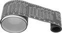 |
Measure outer diameter and mark lines around pipe. A pipe size conversion chart is printed on these chart/rulers. They’re fiber-reinforced rubber for grease, oil, gasoline, and salt water resistance.
For Pipe OD | Lg. | Wd. | Thk. | Measuring Lg. | Graduations (Numeric Graduations) | Color | Graduation Color | Max. Temp., ° F | Each | |||
|---|---|---|---|---|---|---|---|---|---|---|---|---|
Rubber | ||||||||||||
| 1" to 6", 2 mm to 60 cm | 30" | 2 5/8" | 3/64" | 28" | 1/16" (1"), 2 mm (1 cm) | Gray | White | 360 | 8991A71 | 000000 | ||
| 2" to 16", 2 mm to 78 cm | 60" | 3 7/8" | 3/64" | 36" | 1/16" (1"), 2 mm (1 cm) | Gray | White | 360 | 8991A73 | 00000 | ||
| 6" to 30", 2 mm to 77 cm | 120" | 5 1/4" | 3/64" | 36" | 1/16" (1"), 2 mm (1 cm) | Gray | White | 360 | 8991A75 | 00000 | ||
Pipe Contour Gauges

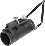
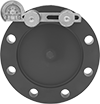
Magnetic Pipe Flange Aligners with Level
 | |
Ensure an even seal around your flange—these tools align and level flanges in a single step. The strong magnets make sure your bolt holes are perfectly inline horizontally and that your flange isn’t tilted. If your flange is made of stainless steel or another nonmagnetic material, secure these aligners using the included threaded cones.
For Flange Hole Dia. | For Max. Flange Hole Ctr.-to-Ctr. Distance | Level Lg. | Aligner Connection Method | Includes | Cone Material | Magnet Material | Container Type | Each | |||
|---|---|---|---|---|---|---|---|---|---|---|---|
Aluminum Body | |||||||||||
| 1/2" to 2" | 9 1/2" | 10 1/2" | Magnetic | Threaded Cones | Steel | Neodymium | Carrying Case | 7049N11 | 0000000 | ||
Pipe Flange Aligners with Protractor
 |
For Flange Hole Dia. | Angle Measured Range | Graduations (Angle Increments) | For Distance Between Bolt Holes | Each | |||
|---|---|---|---|---|---|---|---|
Aluminum | |||||||
| 3/16" to 1 3/4" | 0° to 90° | 2.5° (2°) | 2" to 5 1/2" | 2342A11 | 0000000 | ||
Center-Locating Punches for Curved Surfaces
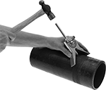 |
Locate and mark the centerline on rods, tubes, and pipes, lay out keyways, and establish angles for connections.
Manual—Manual locators are for use with a hammer. Gently strike the rod to mark the center.
Spring Loaded—Spring-loaded locators mark the center with the pull of a trigger.
Adjustable Dial Protractor—Locators with an adjustable dial protractor aid in establishing marks for angled connections.
Punch Operation | Angle Measured Range | Graduations | Angle Numeric Increments | For Min. Pipe OD | Material | Punch Material | Includes | Features | Each | |||
|---|---|---|---|---|---|---|---|---|---|---|---|---|
| Manual | 0° to 90° | 2.5° | 10° | 1/2" | Aluminum | Steel | Adjustable Dial Protractor | Bubble Level | 2195A1 | 0000000 | ||
| Spring Loaded | 0° to 90° | 2.5° | 10° | 1" | Aluminum | Steel | Adjustable Dial Protractor | Bubble Level | 2195A2 | 000000 | ||
Contour Gauges

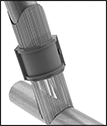
Pipe Flange Aligner Pins with Horizontal Level
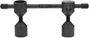
Pipe Flange Aligner Pins
 |
Insert a pair of these nut-and-bolt pins into adjacent flange holes and tighten to align flanges before connecting two pipes. One pin in each pair has a level for vertical alignment. Use a separate level to align the flange horizontally. Also known as two-hole pins.
4 1/2" Lg. Extension—Pins with a 4 ½” length extension let you increase the length of your pins to align thicker flanges.
Two Couplings—Use the included couplings to connect the extension to your pins.

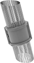
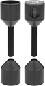
Magnetic Pipe Flange Aligner Pins
Swiftly and accurately align pipe flange bolt holes without the hassle of threads. These pins have strong magnets that snap together. Insert them into adjacent bolt holes to help make sure flanges are parallel before connecting pipes. Also known as two-hole pins.
For 2 3/4" Flange Thickness—Pins for 2 3/4" thick flanges can be used with pipe flange aligner extensions (sold separately) to lengthen their reach for flanges up to 3 1/2″ thick.
Pipe Flange Aligners | Pipe Flange Aligner Extensions | |||||||||
|---|---|---|---|---|---|---|---|---|---|---|
For Flange | ||||||||||
Hole Dia. | Thk. | Aligner Connection Method | Magnet Material | Pair | Lg. | Each | ||||
Steel | ||||||||||
| 5/16" to 7/8" | 7/8" | Magnetic | Neodymium | 7065N11 | 000000 | — | ——— | 0 | ||
| 1/2" to 1 7/16" | 1 3/8" | Magnetic | Neodymium | 7065N12 | 000000 | — | ——— | 0 | ||
| 3/4" to 1 15/16" | 2 3/4" | Magnetic | Neodymium | 7065N13 | 000000 | 1 3/4" | 7065N14 | 000000 | ||
