About Thumb Screw and Binding Post Materials
More
Stainless Steel Wing-Head Thumb Screws

Made from 18-8 stainless steel, these thumb screws are chemical resistant and may be mildly magnetic. Wings provide more leverage than spade-head thumb screws for greater torque while tightening. Length is measured from under the head.
Head | |||||
|---|---|---|---|---|---|
| Lg. | Wd. | Ht. | Specifications Met | Each | |
18-8 Stainless Steel | |||||
1/4"-20 | |||||
| 3/4" | 1 1/2" | 5/8" | __ | 000000000 | 000000 |
| 1" | 1 1/2" | 5/8" | __ | 000000000 | 00000 |
| 1 1/2" | 1 1/2" | 5/8" | __ | 000000000 | 00000 |
| 2" | 1 1/2" | 5/8" | __ | 000000000 | 00000 |
| 3" | 1 1/2" | 5/8" | __ | 000000000 | 00000 |
5/16"-18 | |||||
| 3/4" | 1 11/16" | 23/32" | __ | 000000000 | 00000 |
| 1" | 1 11/16" | 23/32" | __ | 000000000 | 00000 |
| 1 1/2" | 1 11/16" | 23/32" | __ | 000000000 | 00000 |
| 2" | 1 11/16" | 23/32" | __ | 000000000 | 00000 |
| 3" | 1 11/16" | 23/32" | __ | 000000000 | 00000 |
3/8"-16 | |||||
| 3/4" | 1 7/8" | 13/16" | __ | 000000000 | 00000 |
| 1" | 1 7/8" | 13/16" | __ | 000000000 | 00000 |
| 1 1/2" | 1 7/8" | 13/16" | __ | 000000000 | 00000 |
| 2" | 1 7/8" | 13/16" | __ | 000000000 | 00000 |
| 3" | 1 7/8" | 13/16" | __ | 000000000 | 00000 |
1/2"-13 | |||||
| 1" | 2 1/4" | 1" | __ | 000000000 | 00000 |
| 1 1/2" | 2 1/4" | 1" | __ | 000000000 | 00000 |
| 2" | 2 1/4" | 1" | __ | 000000000 | 00000 |
| 3" | 2 1/4" | 1" | __ | 000000000 | 00000 |
5/8"-11 | |||||
| 1" | 2 5/8" | 1 3/16" | __ | 000000000 | 00000 |
| 2" | 2 5/8" | 1 3/16" | __ | 000000000 | 00000 |
| 3" | 2 5/8" | 1 3/16" | __ | 000000000 | 00000 |
M3 × 0.5 mm | |||||
| 12mm | 17.6mm | 8.6mm | DIN 316 | 000000000 | 0000 |
| 20mm | 17.6mm | 8.6mm | DIN 316 | 000000000 | 000 |
| 30mm | 17.6mm | 8.6mm | DIN 316 | 000000000 | 0000 |
M4 × 0.7 mm | |||||
| 10mm | 23mm | 11.5mm | DIN 316 | 000000000 | 0000 |
| 12mm | 23mm | 11.5mm | DIN 316 | 000000000 | 0000 |
| 16mm | 23mm | 11.5mm | DIN 316 | 000000000 | 0000 |
| 20mm | 23mm | 11.5mm | DIN 316 | 000000000 | 0000 |
| 25mm | 23mm | 11.5mm | DIN 316 | 000000000 | 0000 |
| 30mm | 23mm | 11.5mm | DIN 316 | 000000000 | 0000 |
| 35mm | 23mm | 11.5mm | DIN 316 | 000000000 | 0000 |
M5 × 0.8 mm | |||||
| 10mm | 23mm | 11.5mm | DIN 316 | 000000000 | 0000 |
| 12mm | 23mm | 11.5mm | DIN 316 | 000000000 | 0000 |
| 16mm | 23mm | 11.5mm | DIN 316 | 000000000 | 0000 |
| 20mm | 23mm | 11.5mm | DIN 316 | 000000000 | 0000 |
| 25mm | 23mm | 11.5mm | DIN 316 | 000000000 | 0000 |
| 30mm | 23mm | 11.5mm | DIN 316 | 000000000 | 0000 |
| 35mm | 23mm | 11.5mm | DIN 316 | 000000000 | 0000 |
| 50mm | 23mm | 11.5mm | DIN 316 | 000000000 | 0000 |
M6 × 1 mm | |||||
| 10mm | 28mm | 14mm | DIN 316 | 000000000 | 0000 |
| 12mm | 28mm | 14mm | DIN 316 | 000000000 | 0000 |
| 16mm | 28mm | 14mm | DIN 316 | 000000000 | 0000 |
| 20mm | 28mm | 14mm | DIN 316 | 000000000 | 0000 |
| 25mm | 28mm | 14mm | DIN 316 | 000000000 | 0000 |
| 30mm | 28mm | 14mm | DIN 316 | 000000000 | 0000 |
| 35mm | 28mm | 14mm | DIN 316 | 000000000 | 0000 |
| 40mm | 28mm | 14mm | DIN 316 | 000000000 | 0000 |
| 50mm | 28mm | 14mm | DIN 316 | 000000000 | 0000 |
M8 × 1.25 mm | |||||
| 16mm | 31mm | 16mm | DIN 316 | 000000000 | 0000 |
| 20mm | 31mm | 16mm | DIN 316 | 000000000 | 0000 |
| 25mm | 31mm | 16mm | DIN 316 | 000000000 | 0000 |
| 30mm | 31mm | 16mm | DIN 316 | 000000000 | 0000 |
| 35mm | 31mm | 16mm | DIN 316 | 000000000 | 0000 |
| 40mm | 31mm | 16mm | DIN 316 | 000000000 | 0000 |
| 50mm | 31mm | 16mm | DIN 316 | 000000000 | 0000 |
M10 × 1.5 mm | |||||
| 20mm | 37mm | 18mm | DIN 316 | 000000000 | 00000 |
| 25mm | 37mm | 18mm | DIN 316 | 000000000 | 0000 |
| 30mm | 37mm | 18mm | DIN 316 | 000000000 | 00000 |
| 35mm | 37mm | 18mm | DIN 316 | 000000000 | 00000 |
| 40mm | 37mm | 18mm | DIN 316 | 000000000 | 00000 |
| 50mm | 37mm | 18mm | DIN 316 | 000000000 | 00000 |
| 60mm | 37mm | 18mm | DIN 316 | 000000000 | 00000 |
M12 × 1.75 mm | |||||
| 35mm | 50mm | 24mm | DIN 316 | 000000000 | 00000 |
| 50mm | 50mm | 24mm | DIN 316 | 000000000 | 00000 |
Steel and Iron Wing-Head Thumb Screws


Wings provide more leverage than spade-head thumb screws for greater torque while tightening. A zinc plating provides corrosion resistance in wet environments. Length is measured from under the head.
Head | ||||||
|---|---|---|---|---|---|---|
| Lg. | Wd. | Ht. | Pkg. Qty. | Pkg. | ||
Zinc-Plated Iron | ||||||
10-24 | ||||||
| 1 | 1/2" | 1 1/16" | 1/2" | 1 | 000000000 | 00000 |
| 1 | 3/4" | 1 1/16" | 1/2" | 1 | 000000000 | 0000 |
| 1 | 1" | 1 1/16" | 1/2" | 1 | 000000000 | 0000 |
| 1 | 1 1/2" | 1 1/16" | 1/2" | 1 | 000000000 | 0000 |
1/4"-20 | ||||||
| 1 | 1/2" | 1 3/8" | 5/8" | 1 | 000000000 | 0000 |
| 1 | 3/4" | 1 3/8" | 5/8" | 1 | 000000000 | 0000 |
| 1 | 1" | 1 3/8" | 5/8" | 1 | 000000000 | 0000 |
| 1 | 1 1/2" | 1 3/8" | 5/8" | 1 | 000000000 | 0000 |
| 1 | 2" | 1 3/8" | 5/8" | 1 | 000000000 | 0000 |
| 1 | 2 1/2" | 1 3/8" | 5/8" | 1 | 000000000 | 0000 |
| 1 | 3" | 1 3/8" | 5/8" | 1 | 000000000 | 0000 |
5/16"-18 | ||||||
| 2 | 3/4" | 1 3/4" | 3/4" | 1 | 000000000 | 0000 |
| 2 | 1" | 1 3/4" | 3/4" | 1 | 000000000 | 0000 |
| 2 | 1 1/2" | 1 3/4" | 3/4" | 1 | 000000000 | 0000 |
| 2 | 2" | 1 3/4" | 3/4" | 1 | 000000000 | 0000 |
| 2 | 2 1/2" | 1 3/4" | 3/4" | 1 | 000000000 | 0000 |
| 2 | 3" | 1 3/4" | 3/4" | 1 | 000000000 | 0000 |
3/8"-16 | ||||||
| 2 | 3/4" | 1 13/16" | 7/8" | 1 | 000000000 | 0000 |
| 2 | 1" | 1 13/16" | 7/8" | 1 | 000000000 | 0000 |
| 2 | 1 1/2" | 1 13/16" | 7/8" | 1 | 000000000 | 0000 |
| 2 | 2" | 1 13/16" | 7/8" | 1 | 000000000 | 0000 |
| 2 | 3" | 1 13/16" | 7/8" | 1 | 000000000 | 0000 |
1/2"-13 | ||||||
| 2 | 1" | 2 1/4" | 1" | 1 | 000000000 | 0000 |
| 2 | 2" | 2 1/4" | 1" | 1 | 000000000 | 0000 |
| 2 | 2 1/2" | 2 1/4" | 1" | 1 | 000000000 | 0000 |
| 2 | 3" | 2 1/4" | 1" | 1 | 000000000 | 0000 |
Zinc-Plated Steel | ||||||
8-32 | ||||||
| 3 | 1/4" | 49/64" | 25/64" | 10 | 000000000 | 00000 |
| 3 | 3/8" | 49/64" | 25/64" | 10 | 000000000 | 00000 |
| 3 | 1/2" | 49/64" | 25/64" | 10 | 000000000 | 00000 |
10-32 | ||||||
| 3 | 1/2" | 57/64" | 29/64" | 10 | 000000000 | 00000 |
| 3 | 3/4" | 57/64" | 29/64" | 10 | 000000000 | 00000 |
| 3 | 1" | 57/64" | 29/64" | 10 | 000000000 | 00000 |
1/4"-20 | ||||||
| 3 | 3/8" | 1 5/64" | 29/64" | 10 | 000000000 | 00000 |
| 3 | 1/2" | 1 5/64" | 29/64" | 10 | 000000000 | 00000 |
| 3 | 5/8" | 1 5/64" | 29/64" | 10 | 000000000 | 00000 |
| 3 | 3/4" | 1 5/64" | 29/64" | 10 | 000000000 | 00000 |
| 3 | 1" | 1 5/64" | 29/64" | 5 | 000000000 | 0000 |
| 3 | 1 1/2" | 1 5/64" | 29/64" | 5 | 000000000 | 0000 |
5/16"-18 | ||||||
| 3 | 1/2" | 1 19/64" | 39/64" | 5 | 000000000 | 0000 |
| 3 | 3/4" | 1 19/64" | 39/64" | 5 | 000000000 | 0000 |
| 3 | 1" | 1 19/64" | 39/64" | 5 | 000000000 | 0000 |
Metric Iron Wing-Head Thumb Screws

These thumb screws have wings that provide more leverage than spade-head thumb screws for greater torque while tightening. A zinc plating provides corrosion resistance in wet environments. Length is measured from under the head.
Head, mm | |||||
|---|---|---|---|---|---|
| Lg., mm | Wd. | Ht. | Specifications Met | Each | |
Zinc-Plated Cast Iron | |||||
M4 × 0.7 mm | |||||
| 8 | 20 | 10.5 | DIN 316 | 000000000 | 00000 |
| 10 | 20 | 10.5 | DIN 316 | 000000000 | 0000 |
| 16 | 20 | 10.5 | DIN 316 | 000000000 | 0000 |
| 20 | 20 | 10.5 | DIN 316 | 000000000 | 0000 |
| 40 | 20 | 10.5 | DIN 316 | 000000000 | 0000 |
M5 × 0.8 mm | |||||
| 10 | 26 | 13 | DIN 316 | 000000000 | 0000 |
| 12 | 26 | 13 | DIN 316 | 000000000 | 0000 |
| 16 | 26 | 13 | DIN 316 | 000000000 | 0000 |
| 20 | 26 | 13 | DIN 316 | 000000000 | 0000 |
| 25 | 26 | 13 | DIN 316 | 000000000 | 0000 |
| 40 | 26 | 13 | DIN 316 | 000000000 | 0000 |
M6 × 1 mm | |||||
| 10 | 33 | 17 | DIN 316 | 000000000 | 0000 |
| 12 | 33 | 17 | DIN 316 | 000000000 | 0000 |
| 16 | 33 | 17 | DIN 316 | 000000000 | 0000 |
| 20 | 33 | 17 | DIN 316 | 000000000 | 0000 |
| 25 | 33 | 17 | DIN 316 | 000000000 | 0000 |
| 30 | 33 | 17 | DIN 316 | 000000000 | 0000 |
| 50 | 33 | 17 | DIN 316 | 000000000 | 0000 |
| 60 | 33 | 17 | DIN 316 | 000000000 | 0000 |
M8 × 1.25 mm | |||||
| 12 | 39 | 20 | DIN 316 | 000000000 | 0000 |
| 16 | 39 | 20 | DIN 316 | 000000000 | 0000 |
| 20 | 39 | 20 | DIN 316 | 000000000 | 0000 |
| 25 | 39 | 20 | DIN 316 | 000000000 | 0000 |
| 30 | 39 | 20 | DIN 316 | 000000000 | 0000 |
| 40 | 39 | 20 | DIN 316 | 000000000 | 0000 |
| 50 | 39 | 20 | DIN 316 | 000000000 | 0000 |
| 80 | 39 | 20 | DIN 316 | 000000000 | 0000 |
Two-Arm Plastic-Head Thumb Screws
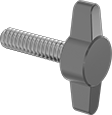
Arms provide a flat surface to push your fingers against. Length is measured from under the head.
Head | |||||||||
|---|---|---|---|---|---|---|---|---|---|
| Lg. | Threading | Min. Thread Lg. | Wd. | Ht. | Temperature Range, °F | Color | Pkg. Qty. | Pkg. | |
18-8 Stainless Steel | |||||||||
10-24 | |||||||||
| 1/2" | Fully Threaded | __ | 1" | 1/4" | 32° to 180° | Black | 25 | 000000000 | 000000 |
| 5/8" | Fully Threaded | __ | 1" | 1/4" | 32° to 180° | Black | 25 | 000000000 | 00000 |
| 3/4" | Fully Threaded | __ | 1" | 1/4" | 32° to 180° | Black | 25 | 000000000 | 00000 |
| 1" | Fully Threaded | __ | 1" | 1/4" | 32° to 180° | Black | 10 | 000000000 | 0000 |
10-32 | |||||||||
| 3/8" | Fully Threaded | __ | 1" | 1/4" | 32° to 180° | Black | 25 | 000000000 | 00000 |
| 1/2" | Fully Threaded | __ | 1" | 1/4" | 32° to 180° | Black | 25 | 000000000 | 00000 |
| 5/8" | Fully Threaded | __ | 1" | 1/4" | 32° to 180° | Black | 25 | 000000000 | 00000 |
| 3/4" | Fully Threaded | __ | 1" | 1/4" | 32° to 180° | Black | 25 | 000000000 | 00000 |
| 7/8" | Fully Threaded | __ | 1" | 1/4" | 32° to 180° | Black | 10 | 000000000 | 0000 |
| 1" | Fully Threaded | __ | 1" | 1/4" | 32° to 180° | Black | 10 | 000000000 | 0000 |
| 1 1/2" | Partially Threaded | 0.875" | 1" | 1/4" | 32° to 180° | Black | 10 | 000000000 | 00000 |
1/4"-20 | |||||||||
| 3/8" | Fully Threaded | __ | 1 1/4" | 5/16" | 32° to 180° | Black | 10 | 000000000 | 0000 |
| 1/2" | Fully Threaded | __ | 1 1/4" | 5/16" | 32° to 180° | Black | 10 | 000000000 | 0000 |
| 5/8" | Fully Threaded | __ | 1 1/4" | 5/16" | 32° to 180° | Black | 10 | 000000000 | 0000 |
| 3/4" | Fully Threaded | __ | 1 1/4" | 5/16" | 32° to 180° | Black | 10 | 000000000 | 00000 |
| 7/8" | Fully Threaded | __ | 1 1/4" | 5/16" | 32° to 180° | Black | 10 | 000000000 | 00000 |
| 1" | Fully Threaded | __ | 1 1/4" | 5/16" | 32° to 180° | Black | 10 | 000000000 | 00000 |
| 1 1/4" | Fully Threaded | __ | 1 1/4" | 5/16" | 32° to 180° | Black | 10 | 000000000 | 00000 |
| 1 1/2" | Partially Threaded | 1" | 1 1/4" | 5/16" | 32° to 180° | Black | 10 | 000000000 | 00000 |
| 2" | Partially Threaded | 1" | 1 1/4" | 5/16" | 32° to 180° | Black | 5 | 000000000 | 0000 |
5/16"-18 | |||||||||
| 1/2" | Fully Threaded | __ | 1 1/2" | 13/32" | 32° to 180° | Black | 10 | 000000000 | 00000 |
| 5/8" | Fully Threaded | __ | 1 1/2" | 13/32" | 32° to 180° | Black | 10 | 000000000 | 00000 |
| 3/4" | Fully Threaded | __ | 1 1/2" | 13/32" | 32° to 180° | Black | 5 | 000000000 | 0000 |
| 7/8" | Fully Threaded | __ | 1 1/2" | 13/32" | 32° to 180° | Black | 5 | 000000000 | 0000 |
| 1" | Fully Threaded | __ | 1 1/2" | 13/32" | 32° to 180° | Black | 5 | 000000000 | 0000 |
| 1 1/4" | Fully Threaded | __ | 1 1/2" | 13/32" | 32° to 180° | Black | 5 | 000000000 | 0000 |
| 1 1/2" | Fully Threaded | __ | 1 1/2" | 13/32" | 32° to 180° | Black | 5 | 000000000 | 00000 |
Wing Head Quarter-Turn Captive Panel Screws with Rivet-Mount Nut
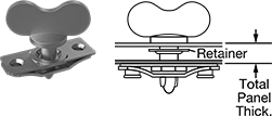

Rivet these nuts into thin panels for a flush fit. They can be mounted without space between panels. A quarter-turn locks and releases access panels, doors, and covers. The screw is held to the outer panel by a retainer. Rivets not included. Install with 3/32" rivets in steel and 1/8" rivets in plastic. Length is measured from under the screw head.
Zinc-plated steel nuts and screws are corrosion resistant in wet environments. An installation tool (sold separately) is required to install the retainer.
Acetal plastic nuts and screws are chemical resistant and lightweight.
For technical drawings and 3-D models, click on a part number.
For Panel Hole Dia. | Head | ||||||||||||
|---|---|---|---|---|---|---|---|---|---|---|---|---|---|
| For Total Panel Thick. | Inner | Outer | Wd. | Ht. | Lg. | Nut Wd. | Shank Dia. | Mounting Hole Ctr.-to-Ctr. | Retainer Material | Temperature Range, °F | Color | Each | |
Zinc-Plated Steel | |||||||||||||
| 0.15" to 0.17" | 0.44" | 0.24" | 0.88" | 0.44" | 0.46" | 0.38" | 0.198" | 0.75" | 18-8 Stainless Steel | __ | __ | 000000000 | 00000 |
| 0.17" to 0.19" | 0.44" | 0.24" | 0.88" | 0.44" | 0.48" | 0.38" | 0.198" | 0.75" | 18-8 Stainless Steel | __ | __ | 000000000 | 0000 |
| 0.19" to 0.21" | 0.44" | 0.24" | 0.88" | 0.44" | 0.5" | 0.38" | 0.198" | 0.75" | 18-8 Stainless Steel | __ | __ | 000000000 | 0000 |
| 0.21" to 0.23" | 0.44" | 0.24" | 0.88" | 0.44" | 0.52" | 0.38" | 0.198" | 0.75" | 18-8 Stainless Steel | __ | __ | 000000000 | 0000 |
| 0.23" to 0.25" | 0.44" | 0.24" | 0.88" | 0.44" | 0.54" | 0.38" | 0.198" | 0.75" | 18-8 Stainless Steel | __ | __ | 000000000 | 0000 |
| 0.25" to 0.27" | 0.44" | 0.24" | 0.88" | 0.44" | 0.56" | 0.38" | 0.198" | 0.75" | 18-8 Stainless Steel | __ | __ | 000000000 | 0000 |
Acetal Plastic | |||||||||||||
| 0.25" to 0.3" | 0.438" | 0.39" | 1.1" | 0.43" | 0.95" | 0.5" | 0.25" | 0.875" | Acetal Plastic | -40° to 190° | Black | 000000000 | 0000 |
| 0.3" to 0.35" | 0.438" | 0.39" | 1.1" | 0.43" | 1" | 0.5" | 0.25" | 0.875" | Acetal Plastic | -40° to 190° | Black | 000000000 | 0000 |
| 0.4" to 0.45" | 0.438" | 0.39" | 1.1" | 0.43" | 1.1" | 0.5" | 0.25" | 0.875" | Acetal Plastic | -40° to 190° | Black | 000000000 | 0000 |
Wing Head Quarter-Turn Captive Panel Screws with Back Press-Fit Nut

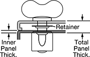
Press these nuts into the backside of a panel in applications where you have access to both sides of the panel. Install with an arbor press or similar pressure tool. A quarter-turn locks and releases access panels, doors, and covers. The screw is held to the outer panel by a retainer. An installation tool (sold separately) is required to install the retainer. Nuts and screws have a zinc plating that provides corrosion resistance in wet environments. Length is measured from under the screw head.
For technical drawings and 3-D models, click on a part number.
For Panel Thick. | Head | ||||||||||
|---|---|---|---|---|---|---|---|---|---|---|---|
| Total | Min. Inner | For Inner Panel Hole Dia. | For Min. Space Between Panels | Wd. | Ht. | Lg. | Nut Dia. | Shank Dia. | Retainer Material | Each | |
Zinc-Plated Steel | |||||||||||
| 0.05" to 0.07" | 0.037" | 0.437" | 0.01" | 0.88" | 0.44" | 0.46" | 0.54" | 0.198" | 18-8 Stainless Steel | 000000000 | 00000 |
| 0.07" to 0.09" | 0.037" | 0.437" | 0.01" | 0.88" | 0.44" | 0.48" | 0.54" | 0.198" | 18-8 Stainless Steel | 000000000 | 0000 |
| 0.09" to 0.11" | 0.037" | 0.437" | 0.01" | 0.88" | 0.44" | 0.5" | 0.54" | 0.198" | 18-8 Stainless Steel | 000000000 | 0000 |
| 0.11" to 0.13" | 0.037" | 0.437" | 0.01" | 0.88" | 0.44" | 0.52" | 0.54" | 0.198" | 18-8 Stainless Steel | 000000000 | 0000 |
| 0.13" to 0.15" | 0.037" | 0.437" | 0.01" | 0.88" | 0.44" | 0.54" | 0.54" | 0.198" | 18-8 Stainless Steel | 000000000 | 0000 |
| 0.15" to 0.17" | 0.037" | 0.437" | 0.01" | 0.88" | 0.44" | 0.56" | 0.54" | 0.198" | 18-8 Stainless Steel | 000000000 | 0000 |
Wing Head Quarter-Turn Captive Panel Screws with Front Press-Fit Nut

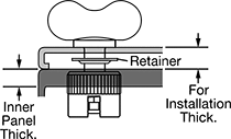
Press these nuts into a closed-end hole or thick panel in applications where the back of the panel is inaccessible. Install with an arbor press or similar pressure tool. A quarter-turn locks and releases access panels, doors, and covers. The screw is held to the outer panel by a retainer. An installation tool (sold separately) is required to install the retainer. Nuts and screws have a zinc plating to resist corrosion in wet environments. Length is measured from under the screw head.
For technical drawings and 3-D models, click on a part number.
For Inner Panel | Head | ||||||||||
|---|---|---|---|---|---|---|---|---|---|---|---|
| For Installation Thick. | Min. Thick. | Hole Dia. | For Min. Space Between Panels | Wd. | Ht. | Lg. | Nut Dia. | Shank Dia. | Retainer Material | Each | |
Zinc-Plated Steel | |||||||||||
| 0.01"-0.03" | 0.08" | 0.469" | 0.01" | 0.88" | 0.44" | 0.46" | 0.465" | 0.198" | 18-8 Stainless Steel | 000000000 | 00000 |
| 0.03"-0.05" | 0.08" | 0.469" | 0.01" | 0.88" | 0.44" | 0.48" | 0.465" | 0.198" | 18-8 Stainless Steel | 000000000 | 0000 |
| 0.05"-0.07" | 0.08" | 0.469" | 0.01" | 0.88" | 0.44" | 0.5" | 0.465" | 0.198" | 18-8 Stainless Steel | 000000000 | 0000 |
| 0.07"-0.09" | 0.08" | 0.469" | 0.01" | 0.88" | 0.44" | 0.52" | 0.465" | 0.198" | 18-8 Stainless Steel | 000000000 | 0000 |
| 0.09"-0.11" | 0.08" | 0.469" | 0.01" | 0.88" | 0.44" | 0.54" | 0.465" | 0.198" | 18-8 Stainless Steel | 000000000 | 0000 |
| 0.11"-0.13" | 0.08" | 0.469" | 0.01" | 0.88" | 0.44" | 0.56" | 0.465" | 0.198" | 18-8 Stainless Steel | 000000000 | 0000 |
Wing Head Quarter-Turn Captive Panel Screws with Clip-On Nut
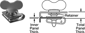
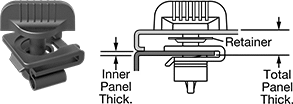
A clip-on nut allows you to mount the screw near the edge of a thin panel. Lock and release access panels, doors, and covers with a quarter-turn. The screw is held to the outer panel by a retainer. Length is measured from under the screw head.
Zinc-plated steel nuts and screws are corrosion resistant in wet environments. An installation tool (sold separately) is required to install the retainer.
Acetal plastic nuts and screws are chemical resistant and lightweight.
For technical drawings and 3-D models, click on a part number.
For Panel Thick. | Head | |||||||||||
|---|---|---|---|---|---|---|---|---|---|---|---|---|
| Inner | Total | For Hole Dia. | Wd. | Ht. | Lg. | Nut Wd. | Shank Dia. | Retainer Material | Temperature Range, °F | Color | Each | |
Zinc-Plated Steel | ||||||||||||
| 0.02" to 0.114" | 0.15" to 0.17" | 0.312" | 0.88" | 0.44" | 0.46" | 0.63" | 0.198" | 18-8 Stainless Steel | __ | __ | 000000000 | 00000 |
| 0.02" to 0.134" | 0.17" to 0.19" | 0.312" | 0.88" | 0.44" | 0.48" | 0.63" | 0.198" | 18-8 Stainless Steel | __ | __ | 000000000 | 0000 |
| 0.02" to 0.154" | 0.19" to 0.21" | 0.312" | 0.88" | 0.44" | 0.5" | 0.63" | 0.198" | 18-8 Stainless Steel | __ | __ | 000000000 | 0000 |
| 0.02" to 0.174" | 0.21" to 0.23" | 0.312" | 0.88" | 0.44" | 0.52" | 0.63" | 0.198" | 18-8 Stainless Steel | __ | __ | 000000000 | 0000 |
| 0.02" to 0.194" | 0.23" to 0.25" | 0.312" | 0.88" | 0.44" | 0.54" | 0.63" | 0.198" | 18-8 Stainless Steel | __ | __ | 000000000 | 0000 |
| 0.02" to 0.214" | 0.25" to 0.27" | 0.312" | 0.88" | 0.44" | 0.56" | 0.63" | 0.198" | 18-8 Stainless Steel | __ | __ | 000000000 | 0000 |
Acetal Plastic | ||||||||||||
| 0.03" to 0.09" | 0.29" to 0.34" | 0.512" | 1.1" | 0.43" | 0.95" | 0.945" | 0.25" | Acetal Plastic | -40° to 190° | Black | 000000000 | 0000 |
| 0.03" to 0.09" | 0.34" to 0.39" | 0.512" | 1.1" | 0.43" | 1" | 0.945" | 0.25" | Acetal Plastic | -40° to 190° | Black | 000000000 | 0000 |
| 0.03" to 0.09" | 0.44" to 0.49" | 0.512" | 1.1" | 0.43" | 1.1" | 0.945" | 0.25" | Acetal Plastic | -40° to 190° | Black | 000000000 | 0000 |


