


Timing Adjustment Style Timing Adjustment Style |
|---|
 |  |
| Push Button | Trippers |
 | |
| Knob |
Input Voltage Input Voltage |
|---|
|
|
Maximum On/Off Cycles Maximum On/Off Cycles |
|---|
|
|
Wire Connection Type Wire Connection Type |
|---|
 | Screw Terminals |
| Wire Leads | |
| Quick- Disconnect Terminals | |
Height Height |
|---|
|
|
|
DFARS (Defense Acquisition Regulations Supplement) DFARS (Defense AcquisitionRegulations Supplement) |
|---|
Plug Type Plug Type |
|---|
|
Minimum Operating Voltage Minimum Operating Voltage |
|---|
|
|
RoHS (Restriction of Hazardous Substances) RoHS (Restriction ofHazardous Substances) |
|---|
|
REACH (Registration, Evaluation, Authorization and Restriction of Chemicals) REACH (Registration,Evaluation, Authorization and Restriction of Chemicals) |
|---|
|
Time and Day Activated Switches
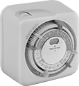
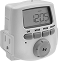
Program these switches to turn a device on and off at a set time and day. They have a three-prong outlet to plug devices directly into the switch. Use with lamps and other small electrical loads. All have an override to bypass the programmed on/off settings.
24-hour switches repeat the same program daily.
Seven-day switches can perform a different program each day of the week.
Switches with trippers are programmed by setting on and off times by positioning trippers around the clock dial.
Switches with astronomical timing can be set to turn lights on and off based on sunrise and sunset.
| Maximum On/Off Cycles | Minimum Set Time | Timing Adjustment Style | Tripper Type | No. of Trippers | Switching Current @ Voltage | No. of Outlets | Features | Ht. | Wd. | Dp. | Plug Type | Each | |
24-Hour Timing Cycle | |||||||||||||
|---|---|---|---|---|---|---|---|---|---|---|---|---|---|
| 3 per Day | 30 min. | Trippers | Removable | 6 | 15 A @ 120 V AC | 1 | __ | 3 1/4" | 3 1/4" | 3 1/4" | Three Prong | 0000000 | 000000 |
7-Day Timing Cycle | |||||||||||||
| 14 per Day | 1 min. | Push Button | __ | __ | 15 A @ 120 V AC | 2 | Astronomical Timing, Random On/Off Option | 3" | 3 1/2" | 3 1/2" | Three Prong | 0000000 | 00000 |
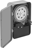
Outdoor Time and Day Activated Switches
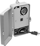
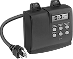
Designed to work with landscape lighting and filter pumps, these switches turn equipment on and off at a set time and day. They control two devices at once, and have three-prong outlets to plug devices directly into the switch. All have an override to bypass the programmed on/off settings.
24-hour switches repeat the same program daily. Position trippers around the clock dial to set on and off times.
Seven-day switches can perform a different program each day of the week. They have astronomical timing that can be set to turn lights on and off based on sunrise and sunset.
Switches with light sensor control allow one device to be controlled by the presence or absence of light.
NEMA 3R rated switches are protected against falling liquids and light splashing.
Mounting | ||||||||||||||||||
|---|---|---|---|---|---|---|---|---|---|---|---|---|---|---|---|---|---|---|
| Maximum On/Off Cycles | Minimum Set Time | Timing Adjustment Style | Tripper Type | No. of Trippers | Switching Current @ Voltage | No. of Outlets | Features | Ht. | Wd. | Dp. | Plug Type | Cord Lg., ft. | Fasteners Included | No. of Holes | Hole Dia. | Min. Ht., ft. | Each | |
24-Hour Timing Cycle—NEMA 3R | ||||||||||||||||||
| 12 per Day | 30 min. | Trippers | Removable | 4 | 15 A @ 120 V AC | 2 | Light Sensor Control | 9 3/8" | 5 1/2" | 3 3/8" | Three Prong | 2 | No | 4 | 1/4" | __ | 0000000 | 0000000 |
7-Day Timing Cycle | ||||||||||||||||||
| 7 per Day | 1 min. | Push Button | __ | __ | 15 A @ 120 V AC | 2 | Astronomical Timing, Random On/Off Option | 5 1/8" | 5 1/4" | 1 7/8" | Three Prong | 2 | No | 2 | 0.31" | 4.5 | 0000000 | 00000 |
| Additional Trippers (Pkg. of 2 Pair) | 0000000 | Pkg. | 00000 |
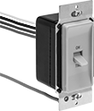
Outlet-Box-Mount Time and Day Activated Switches
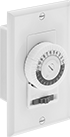
Switches fit single device (1 gang) outlet boxes. Program them to turn a device on and off at a set time and day. They’re often used with lamps and other small electrical loads.
24-hour switches repeat the same program daily. Position trippers around the clock dial to set on and off times.
Seven-day switches can perform a different program each day of the week. Use the astronomical timing to turn lights on and off based on sunrise and sunset; this option can be used independently or in combination with timed programming.
| No. of Circuits Controlled | Switching Current @ Voltage | Maximum On/Off Cycles | Minimum Set Time | Timing Adjustment Style | Tripper Type | Features | Industry Designation | For Outlet Box Type | Wire Connection Type | Wire Lead Lg. | Each | |
24-Hour Timing Cycle | ||||||||||||
|---|---|---|---|---|---|---|---|---|---|---|---|---|
| 1 | 20 A @ 120 V AC | 24 per Day | 30 min. | Trippers | Captive | On/Off/Timer Selector | SPST | 1 Device (1 Gang) | Wire Leads | 6" | 000000 | 000000 |
7-Day Timing Cycle | ||||||||||||
| 1 | 15 A @ 120 V AC | 40 per Week | 1 min. | Push Button | __ | Astronomical Timing, Battery Backup, LCD Display | __ | 1 Device (1 Gang) | Wire Leads | 6" | 0000000 | 00000 |
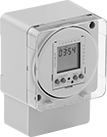
Surface/DIN-Rail Mount Time and Day Activated Switches
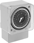
Mount these switches to a flat surface or attach to DIN rail. Program them to turn a device on and off at a set time and day. Position trippers around the clock dial to set on and off times. These switches have a 24-hour timing cycle that repeats the same program daily. As UL and C-UL Recognized Components that are also CSA Certified and CE Marked, they meet American, Canadian, and European safety standards.
Mounting | ||||||||||||||||||
|---|---|---|---|---|---|---|---|---|---|---|---|---|---|---|---|---|---|---|
| No. of Circuits Controlled | Switching Current @ Voltage | Input Voltage | Maximum On/Off Cycles | Minimum Set Time | Timing Adjustment Style | Tripper Type | Industry Designation | Ht. | Wd. | Dp. | Fasteners Included | No. of Holes | Hole Dia. | For DIN Rail Ht., mm | Wire Connection Type | Specifications Met | Each | |
24-Hour Timing Cycle | ||||||||||||||||||
| 1 | 21 A @ 250 V AC | 120V AC | 48 per Day | 15 min. | Trippers | Captive | SPDT | 4.2" | 2.8" | 2.2" | No | 3 | 0.13" | 35 | Screw Terminals | UL Recognized Component, C-UL Recognized Component, CSA Certified, CE Marked | 0000000 | 000000 |
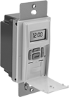
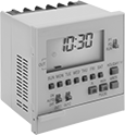
Panel-Mount Time and Day Activated Switches

Install these switches in a panel cutout and program them to turn a device on and off at a set time and day. Position trippers around the clock dial to set on and off times. As UL and C-UL Recognized Components that are also CE Marked, these switches meet American, Canadian, and European safety standards.
24-hour switches repeat the same program daily.
Seven-day switches can perform a different program each day of the week. They come with an override to bypass their programmed settings.
For Panel Cutout | |||||||||||||||||
|---|---|---|---|---|---|---|---|---|---|---|---|---|---|---|---|---|---|
| No. of Circuits Controlled | Switching Current @ Voltage | Input Voltage | Maximum On/Off Cycles | Minimum Set Time | Timing Adjustment Style | Tripper Type | With Override | Industry Designation | Ht. | Wd. | Dp. | Ht. | Wd. | Wire Connection Type | Specifications Met | Each | |
24-Hour Timing Cycle | |||||||||||||||||
| 1 | 21 A @ 250 V AC | 120V AC | 48 per Day | 15 min. | Trippers | Captive | __ | SPDT | 2.8" | 2.8" | 1.5" | 2.63" | 2.63" | Quick-Disconnect Terminals | UL Recognized Component, C-UL Recognized Component, CSA Certified, CE Marked | 0000000 | 000000 |
7-Day Timing Cycle | |||||||||||||||||
| 1 | 21 A @ 250 V AC | 120V AC | 6 per Day | 2 hrs. | Trippers | Captive | With Override | SPDT | 2.8" | 2.8" | 1.5" | 2.63" | 2.63" | Quick-Disconnect Terminals | UL Recognized Component, C-UL Recognized Component, CSA Certified, CE Marked | 0000000 | 000000 |
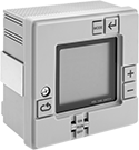
Panel-Mount Set-to-the-Minute Time and Day Activated Switches
Install these switches in a panel cutout. More precise than other time and day switches, they program on/off times for equipment down to the exact minute. The seven-day timing cycle can perform a different program each day of the week. All have an override to bypass the programmed on/off settings. A backup battery maintains the program during a power outage.
Two-circuit switches can apply a different program to each circuit.
For Panel Cutout | ||||||||||||||
|---|---|---|---|---|---|---|---|---|---|---|---|---|---|---|
| No. of Circuits Controlled | Switching Current @ Voltage | Input Voltage | Maximum On/Off Cycles | Minimum Set Time | Timing Adjustment Style | Industry Designation | Ht. | Wd. | Dp. | Ht. | Wd. | Wire Connection Type | Each | |
7-Day Timing Cycle | ||||||||||||||
| 1 | 16 A @ 277 V AC | 24V AC | 20 per Day | 1 min. | Push Button | SPDT | 2.8" | 2.8" | 1.5" | 2.63" | 2.63" | Quick-Disconnect Terminals | 0000000 | 0000000 |
| 1 | 16 A @ 277 V AC | 120V AC | 20 per Day | 1 min. | Push Button | SPDT | 2.8" | 2.8" | 1.5" | 2.63" | 2.63" | Quick-Disconnect Terminals | 00000000 | 000000 |
| 2 | 15 A @ 250 V AC | 120V AC/240V AC | 20 per Day | 1 min. | Push Button | SPST-NO | 2.8" | 2.8" | 2.2" | 2.68" | 2.68" | Screw Terminals | 00000000 | 000000 |
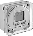
Surface/DIN-Rail Mount Set-to-the-Minute Time and Day Activated Switches
Mount these switches to a flat surface or attach to DIN rail. More precise than other time and day switches, they program on/off times for equipment down to the exact minute. All have an override to bypass the programmed on/off settings. A backup battery maintains the program during a power outage.
24-hour switches repeat the same program daily. They control two circuits and can apply a different program to each circuit.
Seven-day switches can perform a different program each day of the week.
Mounting | For Panel Cutout | |||||||||||||||||
|---|---|---|---|---|---|---|---|---|---|---|---|---|---|---|---|---|---|---|
| No. of Circuits Controlled | Switching Current @ Voltage | Input Voltage | Maximum On/Off Cycles | Minimum Set Time | Timing Adjustment Style | Industry Designation | Ht. | Wd. | Dp. | Fasteners Included | No. of Holes | Hole Dia. | For DIN Rail Ht., mm | Ht. | Wd. | Wire Connection Type | Each | |
24-Hour Timing Cycle | ||||||||||||||||||
| 2 | 15 A @ 250 V AC | 120V AC/240V AC | 12 per Day | 1 min. | Push Button | SPST-NO | 3.8" | 3.8" | 2.2" | No | 2 | __ | 35 | 3.62" | 3.62" | Screw Terminals | 00000000 | 0000000 |
7-Day Timing Cycle | ||||||||||||||||||
| 1 | 16 A @ 277 V AC | 24V AC | 20 per Day | 1 min. | Push Button | SPDT | 4.1" | 2.9" | 2.2" | No | 3 | 0.13" | 35 | __ | __ | Screw Terminals | 00000000 | 000000 |
| 1 | 16 A @ 277 V AC | 120V AC | 20 per Day | 1 min. | Push Button | SPDT | 4.1" | 2.9" | 2.2" | No | 3 | 0.13" | 35 | __ | __ | Screw Terminals | 00000000 | 000000 |
| 1 | 16 A @ 277 V AC | 120V AC | 50 per Day | 1 min. | Push Button | SPDT | 4.1" | 2.9" | 2.2" | No | 3 | 0.13" | 35 | __ | __ | Screw Terminals | 00000000 | 000000 |
| 1 | 16 A @ 277 V AC | 240V AC | 20 per Day | 1 min. | Push Button | SPDT | 4.1" | 2.9" | 2.2" | No | 3 | 0.13" | 35 | __ | __ | Screw Terminals | 00000000 | 000000 |
High-Current Time and Day Activated Switches
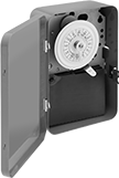
Control equipment with high currents such as landscape lighting, pumps, and heaters. Program these switches to turn a device on and off at a set time and day. Position trippers around the clock dial to set on and off times.
24-hour switches repeat the same program daily.
Seven-day switches can perform a different program each day of the week.
Switches with a day skipper can be programmed to skip operation for one to six days.
Additional trippers (sold separately) are sold in pairs that include one “on” tripper and one “off” tripper.
Switches | Additional Trippers | ||||||||||||||||
|---|---|---|---|---|---|---|---|---|---|---|---|---|---|---|---|---|---|
| No. of Circuits Controlled | Switching Current @ Voltage | Input Voltage | Maximum On/Off Cycles | Minimum Set Time | Tripper Type | No. of Trippers | Industry Designation | Ht. | Wd. | Dp. | Wire Connection Type | Environment | Each | Pkg. Qty. | Pkg. | ||
24-Hour Timing Cycle | |||||||||||||||||
| 1 | 20 A @ 120 V AC, 208 V AC, 240 V AC, 277 V AC | 120V AC/208V AC/240V AC/277V AC | 48 per Day | 15 min. | Captive | 96 | SPDT | 7 3/4" | 5" | 3" | Screw Terminals | Indoor Only | 0000000 | 0000000 | __ | 000000 | 00 |
| 1 | 40 A @ 240 V AC | 120V AC | 12 per Day | 1 hrs. | Removable | 2 | SPST | 7 3/4" | 5" | 3" | Screw Terminals | Indoor Only | 0000000 | 00000 | 1 | 0000000 | 00000 |
| 2 | 40 A @ 240 V AC | 120V AC | 12 per Day | 1 hrs. | Removable | 2 | DPST | 7 3/4" | 5" | 3" | Screw Terminals | Indoor Only | 0000000 | 000000 | 1 | 0000000 | 0000 |
| 2 | 40 A @ 240 V AC | 208V AC/240V AC/277V AC | 12 per Day | 1 hrs. | Removable | 2 | DPST | 7 3/4" | 5" | 3" | Screw Terminals | Indoor Only | 0000000 | 000000 | 1 | 0000000 | 0000 |
24-Hour Timing Cycle with Day Skipper and Three Skip Screws | |||||||||||||||||
| 1 | 40 A @ 240 V AC | 120V AC | 10 per Day | 1 hrs. | Removable | 2 | SPST | 7 3/4" | 5" | 3" | Screw Terminals | Indoor Only | 0000000 | 000000 | 1 | 0000000 | 0000 |
| 2 | 40 A @ 240 V AC | 120V AC | 10 per Day | 1 hrs. | Removable | 2 | DPST | 7 3/4" | 5" | 3" | Screw Terminals | Indoor Only | 0000000 | 000000 | 1 | 0000000 | 0000 |
| 2 | 40 A @ 240 V AC | 208V AC/240V AC/277V AC | 10 per Day | 1 hrs. | Removable | 2 | DPST | 7 3/4" | 5" | 3" | Screw Terminals | Indoor Only | 0000000 | 000000 | 1 | 0000000 | 0000 |
7-Day Timing Cycle | |||||||||||||||||
| 1 | 20 A @ 240 V AC | 120V AC | 12 per Day | 2 hrs. | Captive | 84 | SPDT | 7 3/4" | 5" | 3" | Screw Terminals | Indoor Only | 00000000 | 000000 | __ | 000000 | 00 |
| 4 | 40 A @ 240 V AC | 120V AC | 3 per Day | 3.5 hrs. | Removable | 4 | 4PST-NO | 12 1/2" | 8 1/4" | 4" | Screw Terminals | Indoor Only | 00000000 | 000000 | 7 | 00000000 | 00000 |
| Additional Day-Skip Screws (Pkg. of 3) | 0000000 | Pkg. | 00000 |
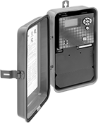
Outdoor High-Current Time and Day Activated Switches
Rated NEMA 3R, these rain-tight switches protect against falling liquids and light splashing. They control equipment with high currents, such as landscape lighting, pumps, and heaters. Program them to turn a device on and off at a set time and day. Position trippers around the clock dial to set on and off times.
24-hour switches repeat the same program daily.
Seven-day switches can perform a different program each day of the week.
Switches with a day skipper can be programmed to skip operation for one to six days.
Additional trippers (sold separately) are sold in pairs that include one “on” tripper and one “off” tripper.
Switches | Additional Trippers | ||||||||||||||||
|---|---|---|---|---|---|---|---|---|---|---|---|---|---|---|---|---|---|
| No. of Circuits Controlled | Switching Current @ Voltage | Input Voltage | Maximum On/Off Cycles | Minimum Set Time | Tripper Type | No. of Trippers | Housing Material | Industry Designation | Ht. | Wd. | Dp. | Wire Connection Type | Each | Pkg. Qty. | Pkg. | ||
24-Hour Timing Cycle | |||||||||||||||||
| 1 | 40 A @ 240 V AC | 120V AC | 12 per Day | 1 hrs. | Removable | 2 | Steel | SPST | 9 3/8" | 5 1/2" | 3 5/8" | Screw Terminals | 0000000 | 0000000 | 1 | 0000000 | 00000 |
| 2 | 40 A @ 240 V AC | 120V AC/208V AC/240V AC/277V AC | 48 per Day | 15 min. | Captive | 96 | Polycarbonate Plastic | DPDT | 8 7/8" | 6 5/8" | 3" | Screw Terminals | 0000000 | 00000 | __ | 000000 | 00 |
| 2 | 40 A @ 240 V AC | 120V AC | 12 per Day | 1 hrs. | Removable | 2 | Steel | DPST | 9 3/8" | 5 1/2" | 3 5/8" | Screw Terminals | 0000000 | 000000 | 1 | 0000000 | 0000 |
| 2 | 40 A @ 240 V AC | 208V AC/240V AC/277V AC | 12 per Day | 1 hrs. | Removable | 2 | Steel | DPST | 9 3/8" | 5 1/2" | 3 5/8" | Screw Terminals | 0000000 | 000000 | 1 | 0000000 | 0000 |
24-Hour Timing Cycle with Day Skipper and Three Skip Screws | |||||||||||||||||
| 2 | 40 A @ 240 V AC | 120V AC | 10 per Day | 1 hrs. | Removable | 2 | Steel | DPST | 9 3/8" | 5 1/2" | 3 5/8" | Screw Terminals | 0000000 | 000000 | 1 | 0000000 | 0000 |
| 2 | 40 A @ 240 V AC | 208V AC/240V AC/277V AC | 10 per Day | 1 hrs. | Removable | 2 | Steel | DPST | 9 3/8" | 5 1/2" | 3 5/8" | Screw Terminals | 0000000 | 000000 | 1 | 0000000 | 0000 |
7-Day Timing Cycle | |||||||||||||||||
| 2 | 40 A @ 240 V AC | 120V AC/208V AC/240V AC/277V AC | 6 per Day | 2 hrs. | Captive | 96 | Polycarbonate Plastic | DPDT | 8 7/8" | 6 5/8" | 3" | Screw Terminals | 00000000 | 000000 | __ | 000000 | 00 |
| 4 | 40 A @ 240 V AC | 120V AC | 3 per Day | 3.5 hrs. | Removable | 14 | Steel | 4PST | 12 1/2" | 8 1/4" | 4" | Screw Terminals | 00000000 | 000000 | 7 | 00000000 | 00000 |
| Additional Day-Skip Screws (Pkg. of 3) | 0000000 | Pkg. | 00000 |
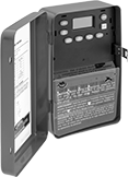
Outdoor Set-to-the-Minute High-Current Time and Day Activated Switches
Rated NEMA 3R, these rain-tight switches protect against falling liquids and light splashing. More precise than other time and day switches, they program on/off times for equipment down to the exact minute. They control equipment with high currents, such as landscape lighting, pumps, and heaters. A backup battery maintains the program during a power outage.
24-hour switches repeat the same program daily.
Seven-day switches can perform a different program each day of the week.
Seven-day/365-day switches can perform a different program each day of the week or year, and compensate for leap year and daylight savings time. Override regular programming for up to 99 holidays for any length of time. They can also be used to activate equipment such as bells and signals for just a few seconds.
Switches with astronomical timing can be set to turn lights on and off based on sunrise and sunset.
Switches with a day skipper can be programmed to skip operation for one to six days.
Mounting | |||||||||||||||
|---|---|---|---|---|---|---|---|---|---|---|---|---|---|---|---|
| No. of Circuits Controlled | Switching Current @ Voltage | Input Voltage | Maximum On/Off Cycles | Minimum Set Time | Timing Adjustment Style | Housing Material | Industry Designation | Ht. | Wd. | Dp. | Fasteners Included | Hole Dia. | Wire Connection Type | Each | |
24-Hour Timing Cycle | |||||||||||||||
With Battery Backup, Lockout | |||||||||||||||
| 1 | 30 A @ 240 V AC | 120V AC/208V AC/240V AC/277V AC | 20 per Day | 1 min. | Push Button | Polycarbonate Plastic | SPST | 8 1/4" | 5" | 3" | No | 0.16" | Screw Terminals | 0000000 | 0000000 |
| 2 | 30 A @ 240 V AC | 120V AC/208V AC/240V AC/277V AC | 20 per Day | 1 min. | Push Button | Polycarbonate Plastic | DPST | 8 1/4" | 5" | 3" | No | 0.16" | Screw Terminals | 0000000 | 000000 |
7-Day Timing Cycle | |||||||||||||||
With Battery Backup, Lockout, Day Skipper | |||||||||||||||
| 2 | 30 A @ 240 V AC | 120V AC/208V AC/240V AC/277V AC | 20 per Day | 1 min. | Push Button | Polycarbonate Plastic | DPST | 8 1/4" | 5" | 3" | No | 0.16" | Screw Terminals | 0000000 | 000000 |
With Battery Backup, Lockout, Day Skipper, Astronomical Timing | |||||||||||||||
| 1 | 30 A @ 240 V AC | 120V AC/208V AC/240V AC/277V AC | 20 per Day | 1 min. | Push Button | Polycarbonate Plastic | SPDT | 8 1/4" | 5" | 3" | No | 0.16" | Screw Terminals | 0000000 | 000000 |
7-Day/365-Day Timing Cycle | |||||||||||||||
With Battery Backup, Lockout, Astronomical Timing | |||||||||||||||
| 1 | 30 A @ 240 V AC | 120V AC/208V AC/240V AC/277V AC | 4,000 per Year | 1 min. | Push Button | Steel | SPDT | 8 5/8" | 5 3/4" | 3 5/8" | No | 0.19" | Screw Terminals | 00000000 | 000000 |
| 2 | 30 A @ 240 V AC | 120V AC/208V AC/240V AC/277V AC | 4,000 per Year | 1 min. | Push Button | Steel | SPDT | 8 5/8" | 5 3/4" | 3 5/8" | No | 0.19" | Screw Terminals | 00000000 | 000000 |
Set-to-the-Minute High-Current Time and Day Activated Switches
For precise control of high-current equipment such as landscape lighting, pumps, and heaters, these switches schedule on/off times to the exact minute. The seven-day timing cycle can perform a different program each day of the week. All have a day skipper that can suspend operation for one to six days. A backup battery maintains the program during a power outage.
Two-circuit switches can apply a different program to each circuit.
Mounting | |||||||||||||||||
|---|---|---|---|---|---|---|---|---|---|---|---|---|---|---|---|---|---|
| No. of Circuits Controlled | Switching Current @ Voltage | Input Voltage | Maximum On/Off Cycles | Minimum Set Time | Timing Adjustment Style | Industry Designation | Ht. | Wd. | Dp. | Fasteners Included | Hole Dia. | Knockout Trade Size | Wire Connection Type | Environment | Specifications Met | Each | |
24 Hour Timing Cycle | |||||||||||||||||
With Capacitor Backup, Lockout, Day Skipper | |||||||||||||||||
| 1 | 30 A @ 240 V AC | 120V AC/208V AC/240V AC/277V AC | 48 per Day | 1 min. | Push Button | SPST | 7 7/8" | 5 1/8" | 3 7/16" | No | 3/16" | 1/2, 3/4 | Screw Terminals | Indoor Only | UL Listed, CSA Certified | 0000000 | 0000000 |
| 2 | 30 A @ 240 V AC | 120V AC/208V AC/240V AC/277V AC | 48 per Day | 1 min. | Push Button | SPST, DPST | 7 7/8" | 5 1/8" | 3 7/16" | No | 3/16" | 1/2, 3/4 | Screw Terminals | Indoor Only | UL Listed, CSA Certified | 0000000 | 000000 |
7-Day Timing Cycle | |||||||||||||||||
With Capacitor Backup, Lockout, Day Skipper | |||||||||||||||||
| 1 | 30 A @ 240 V AC | 120V AC/208V AC/240V AC/277V AC | 48 per Day | 1 min. | Push Button | SPST | 7 7/8" | 5 1/8" | 3 7/16" | No | 3/16" | 1/2, 3/4 | Screw Terminals | Indoor Only | UL Listed, CSA Certified | 0000000 | 000000 |
With Battery Backup, Lockout, Day Skipper | |||||||||||||||||
| 2 | 30 A @ 240 V AC | 120V AC/208V AC/240V AC/277V AC | 28 per Day | 1 min. | Push Button | SPST, DPST | 7 3/4" | 5" | 3" | No | 0.16" | 1/2, 3/4 | Screw Terminals | Indoor Only | UL Listed, CSA Certified | 0000000 | 000000 |
Wall-Mount Timer Switches
Use these switches in place of standard wall switches to automatically turn electrical equipment on or off after a set interval of time. They’re often used with lights.
Switches with override can bypass the automatic shut-off.
Set switches with beep and light signals to alert when the timer is almost done; the signals can also be turned off.
Switches with set time recall retain the last setting; hold the button down to restart the timer with that setting.
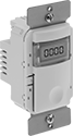
Countdown LCD
and Set Time Recall
| No. of Circuits Controlled | Switch Starting Position | Switching Current @ Voltage | Horsepower @ Switching Voltage | Set Time | For Outlet Box Type | Wire Connection Type | Choose a Color | Each | |
With Override | |||||||||
|---|---|---|---|---|---|---|---|---|---|
| 1 | 1 Off (Normally Open) | 41 mA @ 24 V AC, 12 mA @ 24 V DC | __ | 5 min.-12 hrs. | 1 Device (1 Gang) | Screw Terminals | 000000 | 000000 | |
| 1 | 1 Off (Normally Open) | 6.6 A @ 120 V AC, 4.3 A @ 277 V AC | 1/6 hp @ 125 V AC | 5 min.-12 hrs. | 1 Device (1 Gang) | Screw Terminals | 000000 | 00000 | |
Time-Delay Wall-Mount Timer Switches
Control two devices and delay the shut off of one device by up to one hour. These switches are often used with lights and fans for ventilation. All have an override that bypasses the automatic shut-off.
| Color | No. of Circuits Controlled | Switch Starting Position | Switching Current @ Voltage | Horsepower @ Switching Voltage | Set Time, min. | For Outlet Box Type | Wire Connection Type | Each | |
| Ivory | 2 | 1 Off (Normally Open) | 4.1 A @ 120 V AC | 1/3 hp @ 120 V AC | 1-60 | 1 Device (1 Gang) | Wire Leads | 0000000 | 000000 |
| White | 2 | 1 Off (Normally Open) | 4.1 A @ 120 V AC | 1/3 hp @ 120 V AC | 1-60 | 1 Device (1 Gang) | Wire Leads | 0000000 | 00000 |
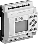
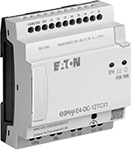
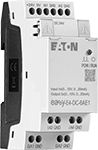
Compact Programmable Logic Controllers
Smaller than other PLCs, these controllers save space in your control cabinet. They combine the functionality of a relay, timer relay, and switch in one unit, so you can program simple automation jobs. All have two types of delayed start (delay-on-make) and two types of delayed switch-off (delay-on-break) timing functions. They have passed strict U.S. and Canadian safety standards, and they’re IP20, which prevents fingers and other objects from making contact with live circuits. Mount them to a 35-mm DIN rail.
Controllers with a display make it easy to monitor or modify your system directly on the unit. Controllers without a display eliminate the risk of accidental adjustments while toggling through information or tampering by unauthorized users.
Program these controllers by connecting them to a computer and installing the required software (sold separately). After the initial programming, these controllers can be updated remotely by a human-machine interface (HMI) or computer.
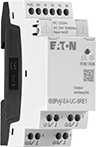
Add expansion modules to increase the number of inputs and outputs. You can connect up to 11 modules to a controller—for a maximum of 188 inputs and outputs. Choose any modules that support the operating voltage of your controller.
![]() For technical drawings and 3-D models, click on a part number.
For technical drawings and 3-D models, click on a part number.
Digital Inputs | Digital Outputs | ||||||||||
|---|---|---|---|---|---|---|---|---|---|---|---|
| Input Signal Type | Voltage | No. of | Voltage | Current | No. of | Signal Type | Operating Voltage | Communication Protocol | Software Included | Each | |
Controllers with Display | |||||||||||
Eaton Easy E4 Series | |||||||||||
| __ | 100-240V AC 100-240V DC | 8 | 240V AC | 8A | 4 | Relay | 100-240V AC 100-240V DC | Modbus TCP/IP | No | 000000 | 0000000 |
| Digital, Analog | 12V DC 24V AC 24V DC 0-10V DC | 8 (4 can be analog) | 240V AC | 8A | 4 | Relay | 12V DC 24V AC 24V DC | Modbus TCP/IP | No | 000000 | 000000 |
| Digital, Analog | 24V DC 0-10V DC | 8 (4 can be analog) | 24V DC | 0.5A | 4 | Transistor | 24V DC | Modbus TCP/IP | No | 0000000 | 000000 |
Controllers without Display | |||||||||||
Eaton Easy E4 Series | |||||||||||
| __ | 100-240V AC 100-240V DC | 8 | 240V AC | 8A | 4 | Relay | 100-240V AC 100-240V DC | Modbus TCP/IP | No | 0000000 | 000000 |
| Digital, Analog | 12V DC 24V AC 24V DC 0-10V DC | 8 (4 can be analog) | 240V AC | 8A | 4 | Relay | 12V DC 24V AC 24V DC | Modbus TCP/IP | No | 0000000 | 000000 |
| Digital, Analog | 24V DC 0-10V DC | 8 (4 can be analog) | 24V DC | 0.5A | 4 | Transistor | 24V DC | Modbus TCP/IP | No | 0000000 | 000000 |
| Manufacturer Model Number | For Operating System | Media Type | Each | |
For Eaton Easy E4 Series | ||||
|---|---|---|---|---|
| EASYSOFT-SWLIC/EasySoft 7 | Windows 7, Windows 8, Windows 8.1, Windows 10 | Download | 000000 | 000000 |
Inputs | Outputs | |||||||
|---|---|---|---|---|---|---|---|---|
| Voltage | No. of | Voltage | Current | No. of | Signal Type | Operating Voltage | Each | |
For Eaton Easy E4 Series | ||||||||
| 100-240V AC 100-240V DC | 4 | 240V AC | 5A | 4 | Relay | 100-240V AC 100-240V DC | 0000000 | 0000000 |
| 100-240V AC 100-240V DC | 8 | 240V AC | 5A | 8 | Relay | 100-240V AC 100-240V DC | 0000000 | 000000 |
| 12V DC 24V AC 24V DC | 4 | 240V AC | 5A | 4 | Relay | 12V DC 24V AC 24V DC | 0000000 | 000000 |
| 12V DC 24V AC 24V DC | 8 | 240V AC | 5A | 8 | Relay | 12V DC 24V AC 24V DC | 0000000 | 000000 |
| 24V DC | 4 | 24V DC | 0.5A | 4 | Transistor | 24V DC | 0000000 | 000000 |
| 24V DC | 8 | 24V DC | 0.5A | 8 | Transistor | 24V DC | 0000000 | 000000 |
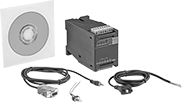
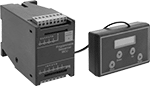
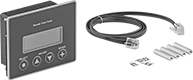
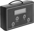
Easy-Program Logic Controllers
Design and operate up to six simultaneous programs without symbols or technical language—the on-screen instructions use simple English. These PLCs combine the functionality of a relay, timer relay, and switch in one unit so you can program complex automation jobs. All have memory backup to retain programming during power outages. Mount to 35-mm DIN rail.
Add expansion modules to increase the number of inputs and outputs. Use either module on its own, or add one of each, but two of the same module won’t work together.
Remote timer panels monitor and adjust up to eight timers while the controller is operating.
Digital Inputs | Digital Outputs | |||||||||||||
|---|---|---|---|---|---|---|---|---|---|---|---|---|---|---|
| Voltage | Current | No. of | Voltage | Current | No. of | Signal Type | Operating Voltage | Wire Connection Type | Terminal Size | Ht. | Wd. | Dp. | Each | |
Controllers with PC Software | ||||||||||||||
| 12-14V DC | 10mA | 6 | 230V AC | 5A | 4 | Relay | 115V AC | Screw Terminals | M3 | 2.9" | 2.2" | 4.3" | 000000 | 0000000 |
Controllers with Hand-Held Programmer | ||||||||||||||
| 12-14V DC | 10mA | 6 | 230V AC | 5A | 4 | Relay | 115V AC | Screw Terminals | M3 | 2.9" | 2.2" | 4.3" | 000000 | 000000 |
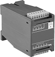
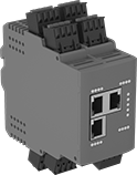
IO Link Controllers and Modules

Create a system of sensors and actuators that you can remotely update, view measurements from, and receive error messages in real time. IO Link systems minimize downtime by locating issues such as cut cables or dirty sensors quickly. They send only digital signals to your PLC, regardless of whether your sensors and actuators send digital or analog signals. Because these systems send digital signals, they’re more reliable and less prone to data error and signal loss than analog signals. It also means you don't have to use expensive shielded cables since they resist EMI.
When retrofitting an existing system, you'll need to make sure your PLC can incorporate IO Link. Check with your PLC manufacturer—most have hardware that allows you to upgrade your PLC to run IO Link.
Controllers communicate between your sensors and actuators and your PLC. They are required. Setting memory automatically stores your settings and restores them once your device is back online. This eliminates needing to program a device again when you replace or fix it. Surface mount controllers let you mount controllers on equipment such as tanks and conveyors. By mounting them on your equipment, you save space in your control cabinet. They use M12 connectors. DIN-rail mount controllers are designed to mount inside your control cabinet, so you can access all your process control devices in a central location. They include RJ45 Ethernet ports to support JSON and MQTT IoT (Internet of Things) protocols, allowing you to link the system directly to your web server to upload information to the Cloud. Connect these ports with RJ45 cords.
Protective caps prevent dust and debris from harming M12 connections when they're not in use. They also help maintain IP ratings by covering unused ports. Stainless steel protective caps have a neoprene gasket, which helps maintain IP69K ratings.
IP rated components block out dust and withstand some water, so they do not require an enclosure. Ports that are unused must be capped to maintain their rating. IP66 rated components withstand washdowns. IP67 rated components can be temporarily submerged in water. IP69K rated components hold up to high-pressure and high-temperature washdowns.
Note: Sockets may have extra holes on their face that are not used.
![]() For technical drawings and 3-D models, click on a part number.
For technical drawings and 3-D models, click on a part number.
Input | Output | |||||||||||||||
|---|---|---|---|---|---|---|---|---|---|---|---|---|---|---|---|---|
| Communication Protocol | No. of Device Ports | Total No. of RJ45 Connections | Total No. of M12 Connections | Type | Signal | Voltage | No. of | Type | Signal | Voltage | Current | No. of | Operating Voltage | Specifications Met | Each | |
Surface Mount | ||||||||||||||||
IP66, IP67 | ||||||||||||||||
| IO Link, Ethernet/IP | 4 | __ | 7 | Digital | PNP | 0-30V DC | 8 | Digital | PNP | 30V DC | 0.3A | 4 | 20-30V DC | UL Listed, C-UL Listed, CE Marked | 0000000 | 0000000 |
| IO Link, Ethernet/IP | 8 | __ | 11 | Digital | PNP | 0-30V DC | 16 | Digital | PNP | 30V DC | 0.3A | 8 | 20-30V DC | UL Listed, C-UL Listed, CE Marked | 0000000 | 000000 |
| IO Link, Profinet | 4 | __ | 7 | Digital | PNP | 0-30V DC | 8 | Digital | PNP | 30V DC | 0.3A | 4 | 20-30V DC | UL Listed, C-UL Listed, CE Marked | 0000000 | 000000 |
| IO Link, Profinet | 8 | __ | 11 | Digital | PNP | 0-30V DC | 16 | Digital | PNP | 30V DC | 0.3A | 8 | 20-30V DC | UL Listed, C-UL Listed, CE Marked | 0000000 | 000000 |
IP66, IP67, IP69K | ||||||||||||||||
| IO Link, Ethernet/IP | 4 | __ | 7 | Digital | PNP | 0-30V DC | 8 | Digital | PNP | 30V DC | 0.3A | 4 | 20-30V DC | UL Listed, C-UL Listed, CE Marked | 0000000 | 000000 |
| IO Link, Ethernet/IP | 8 | __ | 11 | Digital | PNP | 0-30V DC | 16 | Digital | PNP | 30V DC | 0.3A | 8 | 20-30V DC | UL Listed, C-UL Listed, CE Marked | 0000000 | 000000 |
| IO Link, Profinet | 4 | __ | 7 | Digital | PNP | 0-30V DC | 8 | Digital | PNP | 30V DC | 0.3A | 4 | 20-30V DC | UL Listed, C-UL Listed, CE Marked | 0000000 | 000000 |
| IO Link, Profinet | 8 | __ | 11 | Digital | PNP | 0-30V DC | 16 | Digital | PNP | 30V DC | 0.3A | 8 | 20-30V DC | UL Listed, C-UL Listed, CE Marked | 0000000 | 000000 |
DIN-Rail Mount | ||||||||||||||||
IP20 | ||||||||||||||||
| IO Link, Ethernet/IP | 8 | 3 | __ | Digital | PNP | 0-30V DC | 8 | Digital | PNP | 30V DC | 0.3A | 8 | 20-30V DC | UL Listed, C-UL Listed, CE Marked | 0000000 | 000000 |
| IO Link, Profinet | 8 | 3 | __ | Digital | PNP | 0-30V DC | 8 | Digital | PNP | 30V DC | 0.3A | 8 | 20-30V DC | UL Listed, C-UL Listed, CE Marked | 0000000 | 000000 |


For Thread | ||||||
|---|---|---|---|---|---|---|
| Size | Location | Material | Temperature Range, °F | Includes | Each | |
For Plugs | ||||||
| M12 | External | Anodized Aluminum | 0° to 220° | Lanyard | 0000000 | 000000 |
| M12 | External | Stainless Steel | 0° to 220° | Lanyard | 0000000 | 00000 |
For Sockets | ||||||
| M12 | Internal | Anodized Aluminum | 0° to 220° | __ | 0000000 | 00000 |
| M12 | Internal | Stainless Steel | 0° to 220° | Lanyard | 0000000 | 00000 |