


Power Power | Show |
|---|
|
Power Power | Hide |
|---|
For Use With For Use With |
|---|
Power Source Power Source |
|---|
|
Duty Cycle Duty Cycle |
|---|
|
Flow Rate Flow Rate |
|---|
|
Maximum Pressure Maximum Pressure |
|---|
|
|
|
Pump Type Pump Type |
|---|
|
Maximum Feet of Head Maximum Feet of Head |
|---|
|
Housing Material Housing Material |
|---|
|
|
Priming Type Priming Type |
|---|
|
Impeller Material Impeller Material |
|---|
|
Maximum Temperature Maximum Temperature |
|---|
|
Pump Style Pump Style |
|---|
|
RoHS (Restriction of Hazardous Substances) RoHS (Restriction ofHazardous Substances) |
|---|
|
REACH (Registration, Evaluation, Authorization and Restriction of Chemicals) REACH (Registration,Evaluation, Authorization and Restriction of Chemicals) |
|---|
|
System of Measurement System of Measurement |
|---|
|
How to Prime Your Pump
More
How to Determine Feet of Head
More
About Process Pumps
More
About Air Compressors
More
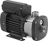
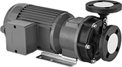
High-Head High-Efficiency Circulation Pumps for Water, Coolants, and Oil
Propel liquid higher and farther than standard high-efficiency circulation pumps. These pumps use less electricity to achieve the same flow rates as other circulation pumps. They have a totally enclosed fan cooled (TEFC) motor for use in dusty, dirty, and damp environments. Adjust the housing studs to make the discharge direction more vertical or horizontal. Pumps are gravity fed and require an elevated liquid source to fully fill the pump before turning on. Do not run dry or use with solids. They cannot be sold to the regions listed due to local energy efficiency requirements.
Note: If flow control is needed, place valves or reducers on the discharge side; never restrict the inlet of a pump with a valve or reducer.
Flow Rate, gpm | Intake (NPT) | Discharge (NPT) | Overall | |||||||||||||||
|---|---|---|---|---|---|---|---|---|---|---|---|---|---|---|---|---|---|---|
| Max. Flow Rate, gpm | @ 100 ft. of Head | @ 110 ft. of Head | @ 120 ft. of Head | Max. Ft. of Head, ft. | Max. Pressure, psi | Max. Viscosity, cP | hp | Current, A | Pipe Size | Gender | Pipe Size | Gender | Lg. | Wd. | Ht. | Cannot Be Sold To | Each | |
208-240/460V AC, Three Phase | ||||||||||||||||||
Hardwire | ||||||||||||||||||
| 80 | 70 | 58 | 47 | 137 | 150 | 17 | 3 | 7.9- 7.4/3.7 | 1 1/2 | Female | 1 1/4 | Female | 18" | 10" | 9 7/8" | Canada | 0000000 | 000000000 |
High-Efficiency Circulation Pumps for Water, Coolants, and Oil
Use less electricity to achieve the same flow rates as other circulation pumps. These pumps have a totally enclosed motor for use in dusty, dirty, and damp environments. Adjust the housing studs to make the discharge direction more vertical or horizontal. Pumps are gravity fed and require an elevated liquid source to fully fill the pump before turning on. Do not run dry or use with solids.
Note: If flow control is needed, place valves or reducers on the discharge side; never restrict the inlet of a pump with a valve or reducer.
Pumps that cannot be sold to the listed regions do not meet energy efficiency requirements.
Pumps | |||||||||||||||||||
|---|---|---|---|---|---|---|---|---|---|---|---|---|---|---|---|---|---|---|---|
Flow Rate, gpm | Intake (NPT) | Discharge (NPT) | Overall | Impellers | |||||||||||||||
| Max. Flow Rate, gpm | @ 40 ft. of Head | @ 50 ft. of Head | Max. ft. of Head | Max. Pressure, psi | Max. Viscosity, cP | hp | Current, A | Pipe Size | Gender | Pipe Size | Gender | Lg. | Wd. | Ht. | Cannot Be Sold To | Each | Each | ||
208-240/460V AC, Three Phase | |||||||||||||||||||
Hardwire | |||||||||||||||||||
| 155 | 125 | 85 | 58 | 100 | 17 | 3 | 7.9- 7.2/3.6 | 2 | Female | 1 1/2 | Female | 17" | 10 1/2" | 8" | Canada | 0000000 | 000000000 | 0000000 | 0000000 |
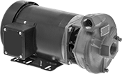
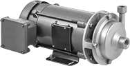
High-Head Circulation Pumps for Water
Also known as booster pumps, these have a multistage impeller that propels water about two times higher and farther than standard circulation pumps. Use them in applications such as water delivery, irrigation, and pressure washing. The motor is totally enclosed fan-cooled (TEFC) for use in dusty, dirty, and damp environments. Pumps are gravity fed and require an elevated liquid source to fully fill the pump before turning on. Do not run dry or use with solids.
Pumps that cannot be sold to California are restricted by local energy efficiency requirements.
Note: If flow control is needed, place valves or reducers on the discharge side; never restrict the inlet of a pump with a valve or reducer.
![]() For technical drawings and 3-D models, click on a part number.
For technical drawings and 3-D models, click on a part number.
Flow Rate | Intake (NPT) | Discharge (NPT) | Overall | ||||||||||||||||
|---|---|---|---|---|---|---|---|---|---|---|---|---|---|---|---|---|---|---|---|
| Max. Flow Rate, gpm | @ 130 ft. of Head | @ 140 ft. of Head | @ 150 ft. of Head | @ 200 ft. of Head | Max. ft. of Head | Max. Pressure, psi | Max. Viscosity, cP | hp | Current, A | Pipe Size | Gender | Pipe Size | Gender | Lg. | Wd. | Ht. | Cannot Be Sold To | Each | |
208-240/440-480V AC, Three Phase | |||||||||||||||||||
Hardwire | |||||||||||||||||||
| 22 | 22 | 22 | 21 | 15 | 254 | 232 | 50 | 3 | 8.2-7.7/4-3.7 | 1 | Female | 1 | Female | 17 1/4" | 6 1/4" | 7 1/2" | CA | 0000000 | 000000000 |
High-Flow Inline Circulation Pumps for Water
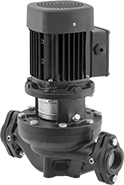
A high-horsepower motor handles four times the flow and twice the pressure of other inline circulation pumps. Install these pumps directly in your pipeline for applications such as hot-water circulation and hydronic heating and cooling. Mount horizontally or vertically. The motor cannot face downward; it’s cooled by the water being pumped. Do not run dry or use with solids.
Note: If flow control is needed, place valves or reducers on the discharge side; never restrict the inlet of a pump with a valve or reducer.
Pumps | ||||||||||||||||||
|---|---|---|---|---|---|---|---|---|---|---|---|---|---|---|---|---|---|---|
Flow Rate, gpm | Intake | Discharge | Overall | Required Pipe Connectors | ||||||||||||||
| Max. Flow Rate, gpm | @ 30 ft. of Head | @ 40 ft. of Head | Max. ft. of Head | Max. Pressure, psi | Max. Viscosity, cP | hp | Current, A | Pipe Size | Thread Type | Pipe Size | Thread Type | Lg. | Wd. | Ht. | Each | Pair | ||
208-240/460V AC, Three Phase—Without Thermal Overload Protection | ||||||||||||||||||
Hardwire | ||||||||||||||||||
| 240 | 188 | 135 | 48 | 145 | 1 | 3 | 8.4-7.7/3.9 | 3 | NPT | 3 | NPT | 8 3/8" | 19" | 24 1/8" | 0000000 | 000000000 | 0000000 | 0000000 |
Self-Priming Circulation Pumps for Water and Coolants
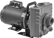
Drain underground tanks and process wastewater with pumps that can be installed up to 20 ft. above your liquid source. They have an open dripproof (ODP) motor for use in clean, dry, and well-ventilated environments. Pumps are self-priming after you fill the pump chamber with liquid. As liquid in the chamber is expelled, a suction force is created which allows the pump to draw liquid upward.
Pumps that cannot be sold to California do not meet energy efficiency requirements.
Note: Pumps must be filled with liquid before use. They need a constant flow of liquid and cannot run dry. If flow control is needed, place valves or reducers on the discharge side; never restrict the inlet of a pump with a valve or reducer.
Pumps | |||||||||||||||||||
|---|---|---|---|---|---|---|---|---|---|---|---|---|---|---|---|---|---|---|---|
Flow Rate, gpm | Intake (NPT) | Discharge (NPT) | Overall | Impellers | |||||||||||||||
| Max. Flow Rate, gpm | @ 50 ft. of Head | @ 70 ft. of Head | Max. ft. of Head | Max. Pressure, psi | Max. Viscosity, cP | hp | Current, A | Pipe Size | Gender | Pipe Size | Gender | Lg. | Wd. | Ht. | Cannot Be Sold To | Each | Each | ||
240/460V AC, Three Phase— Without Thermal Overload Protection | |||||||||||||||||||
Hardwire | |||||||||||||||||||
| 150 | 96 | 64 | 82 | 75 | 1 | 3 | 9/5 | 2 | Female | 2 | Female | 20 3/8" | 7 1/2" | 11 1/8" | CA | 00000000 | 0000000 | 0000000 | 0000000 |
Harsh-Environment Self-Priming Circulation Pumps for Water and Coolants
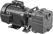
The motor is totally enclosed fan-cooled (TEFC) for use in dusty, dirty, and damp environments. Install these pumps up to 20 ft. above your liquid source to drain underground tanks and process wastewater. They are self-priming after you fill the pump chamber with liquid. As liquid in the chamber is expelled, a suction force is created which allows the pump to draw liquid upward.
Note: Pumps must be filled with liquid before use. They need a constant flow of liquid and cannot run dry. If flow control is needed, place valves or reducers on the discharge side; never restrict the inlet of a pump with a valve or reducer.
Pumps | |||||||||||||||||||
|---|---|---|---|---|---|---|---|---|---|---|---|---|---|---|---|---|---|---|---|
Flow Rate, gpm | Intake (NPT) | Discharge (NPT) | Overall | Impellers | |||||||||||||||
| Max. Flow Rate, gpm | @ 50 ft. of Head | @ 60 ft. of Head | @ 70 ft. of Head | Max. ft. of Head | Max. Pressure, psi | Max. Viscosity, cP | hp | Current, A | Pipe Size | Gender | Pipe Size | Gender | Lg. | Wd. | Ht. | Each | Each | ||
240V AC, Single Phase—With Thermal Overload Protection | |||||||||||||||||||
Hardwire | |||||||||||||||||||
| 120 | 82 | 70 | 58 | 100 | 75 | 1 | 3 | 16 | 1 1/2 | Female | 1 1/2 | Female | 19 1/2" | 9 1/8" | 10" | 00000000 | 0000000 | 000000000 | 000000 |
240/460V AC, Three Phase—Without Thermal Overload Protection | |||||||||||||||||||
Hardwire | |||||||||||||||||||
| 120 | 82 | 70 | 58 | 100 | 75 | 1 | 3 | 8/4 | 1 1/2 | Female | 1 1/2 | Female | 19" | 9 1/8" | 10" | 00000000 | 000000 | 000000000 | 00000 |
| 150 | 76 | 60 | 43 | 82 | 75 | 1 | 3 | 8/4 | 2 | Female | 2 | Female | 20 3/8" | 9 1/8" | 11 1/8" | 00000000 | 000000 | 000000000 | 00000 |
High-Flow Harsh-Environment Self-Priming Circulation Pumps for Water and Coolants
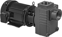
A powerful motor provides twice the flow rate of other self-priming circulation pumps. It is totally enclosed fan-cooled (TEFC) for use in dusty, dirty, and damp environments. Install these pumps up to 20 ft. above your liquid source to drain underground tanks and process wastewater. They are self-priming after you fill the pump chamber with liquid. As liquid in the chamber is expelled, a suction force is created which allows the pump to draw liquid upward.
Note: Pumps must be filled with liquid before use. They need a constant flow of liquid and cannot run dry. If flow control is needed, place valves or reducers on the discharge side; never restrict the inlet of a pump with a valve or reducer.
Pumps | |||||||||||||||||||
|---|---|---|---|---|---|---|---|---|---|---|---|---|---|---|---|---|---|---|---|
Flow Rate, gpm | Intake (NPT) | Discharge (NPT) | Overall | Impellers | |||||||||||||||
| Max. Flow Rate, gpm | @ 40 ft. of Head | @ 50 ft. of Head | @ 60 ft. of Head | Max. ft. of Head | Max. Pressure, psi | Max. Viscosity, cP | hp | Current, A | Pipe Size | Gender | Pipe Size | Gender | Lg. | Wd. | Ht. | Each | Each | ||
208-240/460V AC, Three Phase—Without Thermal Overload Protection | |||||||||||||||||||
Hardwire | |||||||||||||||||||
| 375 | 165 | 130 | 75 | 65 | 125 | 1 | 3 | 10/5 | 3 | Female | 3 | Female | 26 5/8" | 12" | 11 7/8" | 00000000 | 000000000 | 00000000 | 0000000 |
Stainless Steel Circulation Pumps for Chemicals
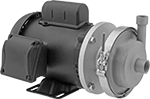
A 316 stainless steel housing sealed with fluoroelastomer resists mild chemicals and acids, such as coolant, oil, and phosphoric acid. These pumps have a totally enclosed fan-cooled (TEFC) motor for use in dusty, dirty, and damp environments. They are gravity fed and require an elevated liquid source. Do not run dry or use with solids.
Note: If flow control is needed, place valves or reducers on the discharge side; never restrict the inlet of a pump with a valve or reducer.
Pumps | ||||||||||||||||||||
|---|---|---|---|---|---|---|---|---|---|---|---|---|---|---|---|---|---|---|---|---|
Flow Rate, gpm | Intake (NPT) | Discharge (NPT) | Overall | Replacement Impellers | ||||||||||||||||
| Max. Flow Rate, gpm | @ 50 ft. of Head | @ 60 ft. of Head | @ 70 ft. of Head | Max. ft. of Head | Max. Pressure, psi | Max. Solids Dia. | Max. Viscosity, cP | hp | Current, A | Pipe Size | Gender | Pipe Size | Gender | Lg. | Wd. | Ht. | Each | Each | ||
240/460V AC, Three Phase—With Thermal Overload Protection | ||||||||||||||||||||
Hardwire | ||||||||||||||||||||
| 130 | 95 | 55 | __ | 79 | 100 | 3/16" | 50 | 3 | 7.6/3.8 | 2 | Female | 1 1/2 | Female | 16" | 9" | 8 3/4" | 0000000 | 000000000 | 0000000 | 0000000 |
| 140 | __ | 85 | 55 | 88 | 100 | 3/32" | 50 | 3 | 7.6/3.8 | 2 | Female | 1 1/2 | Female | 16" | 9" | 8 3/4" | 0000000 | 00000000 | 0000000 | 000000 |
| Maintenance Kit for Pumps with 3/16" or 3/32" Max. Solids Dia. | 0000000 | Each | 0000000 |
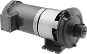
Extended-Life Plastic Circulation Pumps for Chemicals
These pumps have the best chemical resistance of all our circulation pumps. Instead of a shaft seal, they use magnets to turn the impeller, reducing wear and leakage. The motor is totally enclosed fan-cooled (TEFC) for use in dusty, dirty, and damp environments. Pumps are gravity fed and require an elevated liquid source. Do not run dry or use with solids.
Note: If flow control is needed, place valves or reducers on the discharge side; never restrict the inlet of a pump with a valve or reducer.
Pumps | |||||||||||||||||||||
|---|---|---|---|---|---|---|---|---|---|---|---|---|---|---|---|---|---|---|---|---|---|
Flow Rate, gpm | Pipe Size | Overall | Maintenance Kits | Replacement Impellers | |||||||||||||||||
| Max. Flow Rate, gpm | @ 10 ft. of Head | @ 20 ft. of Head | @ 30 ft. of Head | @ 40 ft. of Head | @ 50 ft. of Head | @ 60 ft. of Head | Max. ft. of Head | Max. Viscosity, cP | hp | Current, A | Intake (Gender) | Discharge (Gender) | Lg. | Wd. | Ht. | Each | Each | Each | |||
208–240V AC, 460V AC, Three Phase—Without Thermal Overload Protection | |||||||||||||||||||||
Hardwire | |||||||||||||||||||||
| 120 | 120 | 120 | 120 | 112 | 105 | 92 | 95 | 5 | 3 | 3.9/8-7.8 | 2 (Male) | 1 1/2 (Male) | 24 3/8" | 11 1/2" | 10 1/2" | 0000000 | 000000000 | 00000000 | 000000 | 00000000 | 000000000 |
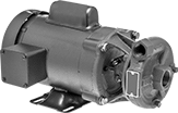
Circulation Pumps for Fuel and Flammable Liquid
Pump fuel and flammable liquids, such as isopropyl alcohol and xylene. These pumps have an explosion-proof motor that is rated for environments where hazardous material is present. Maximum temperature is 250° F or the boiling point of the liquid being pumped, whichever is lower. The motor is totally enclosed fan-cooled (TEFC) for use in dusty, dirty, and damp environments. Pumps are gravity fed and require an elevated liquid source. Do not run dry or use with solids.
Note: If flow control is needed, place valves or reducers on the discharge side; never restrict the inlet of a pump with a valve or reducer.
![]() For technical drawings and 3-D models, click on a part number.
For technical drawings and 3-D models, click on a part number.
Pumps | ||||||||||||||||
|---|---|---|---|---|---|---|---|---|---|---|---|---|---|---|---|---|
Flow Rate, gpm | Pipe Size | Overall | Replacement Impellers | |||||||||||||
| Max. Flow Rate, gpm | @ 40 ft. of Head | @ 60 ft. of Head, gpm | Max. ft. of Head | Max. Pressure, psi | Max. Viscosity, cP | hp | Current, A | Intake (Female, NPT) | Discharge (Female, NPT) | Lg. | Wd. | Ht. | Each | Each | ||
208-240/460V AC, Three Phase—Hardwire | ||||||||||||||||
| 140 | 120 | 47 | 75 | 150 | 264 | 3 | 8.1-7.6/3.8 | 2 | 1 1/2 | 17 1/8" | 11 7/8" | 8 1/2" | 0000000 | 000000000 | 00000000 | 0000000 |
| Maintenance Kit | 00000000 | Each | 0000000 |
Circulation Pumps for Hot Oil
Transfer hot oil up to 650° F in demanding applications such as plastic mold injecting and chemical processing. These pumps have a totally enclosed fan-cooled (TEFC) motor for use in dusty, dirty, and damp environments. They are gravity fed and require an elevated liquid source. Do not run dry or use with solids. They cannot be sold to the regions listed due to local energy efficiency requirements.
Note: If flow control is needed, place valves or reducers on the discharge side; never restrict the inlet of a pump with a valve or reducer.
![]() For technical drawings and 3-D models, click on a part number.
For technical drawings and 3-D models, click on a part number.
Flow Rate, gpm | Intake (NPT) | Discharge (NPT) | Overall | |||||||||||||||||
|---|---|---|---|---|---|---|---|---|---|---|---|---|---|---|---|---|---|---|---|---|
| Pump Style | Max. Flow Rate, gpm | @ 90 ft. of Head | @ 100 ft. of Head | @ 110 ft. of Head | Max. ft. of Head | Max. Pressure, psi | Max. Viscosity, cP | Max. Temp., °F | hp | Current, A | Pipe Size | Gender | Pipe Size | Gender | Lg. | Wd. | Ht. | Cannot Be Sold To | Each | |
240/460V AC, Three Phase—Without Thermal Overload Protection | ||||||||||||||||||||
Hardwire | ||||||||||||||||||||
| Circulating | 86 | 75 | 65 | 54 | 128 | 150 | 32 | 650° | 3 | 7.6/3.8 | 1 1/2 | Female | 1 1/4 | Female | 22" | 9" | 10" | CA, Canada | 0000000 | 000000000 |
Constant-Flow-Rate Pumps for Water
Also known as gear pumps, these produce a smooth flow of liquid for applications such as cooling engines, powering hydraulic equipment, and extracting liquid from holding tanks. Pumps are self-priming after you fill the pump chamber with liquid. As liquid in the chamber is expelled, a suction force is created which allows the pump to draw liquid upward. Do not use with solids.
Pumps with a totally enclosed (TE) or totally enclosed fan-cooled (TEFC) motor can be used in dusty, dirty, and damp environments.
Pumps that cannot be sold to Canada are restricted by local energy efficiency requirements.
Note: Pumps must be filled with liquid before use. They need a constant flow of liquid and cannot run dry. If flow control is needed, place valves or reducers on the discharge side; never restrict the inlet of a pump with a valve or reducer.
![]() For technical drawings and 3-D models, click on a part number.
For technical drawings and 3-D models, click on a part number.
Intake (NPT) | Discharge (NPT) | Overall | ||||||||||||||
|---|---|---|---|---|---|---|---|---|---|---|---|---|---|---|---|---|
| Max. Flow Rate, gpm | Discharge Pressure, psi | Max. Viscosity, cP | Temp. Range, °F | hp | Current, A | Pipe Size | Gender | Pipe Size | Gender | Motor Enclosure Type | Lg. | Wd. | Ht. | Cannot Be Sold To | Each | |
230/460V AC, Three Phase—Without Thermal Overload Protection | ||||||||||||||||
Hardwire | ||||||||||||||||
| 23 | 150 | 100,000 | 32° to 140° | 3 | 8.4/4.2 | 1 | Female | 1 | Female | Totally Enclosed Fan Cooled | 25 1/8" | 10 5/16" | 9 1/16" | Canada | 0000000 | 000000000 |
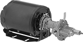
Constant-Flow-Rate Pumps for Oil
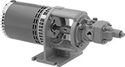
A high-horsepower motor moves oil with a viscosity similar to SAE 60 motor oil. Also known as gear pumps, these produce a smooth flow of liquid to lubricate equipment and blend oils. Motor is open dripproof (ODP) for use in clean, dry, and well-ventilated environments. Pumps are gravity fed and require an elevated liquid source to fully fill the pump before turning on. Do not run dry or use with solids.
Note: If flow control is needed, place valves or reducers on the discharge side; never restrict the inlet of a pump with a valve or reducer.
Intake | Discharge | Overall | |||||||||||||
|---|---|---|---|---|---|---|---|---|---|---|---|---|---|---|---|
| Max. Flow Rate, gpm | Max. Viscosity, cP | Temp. Range, °F | hp | Current, A | Pipe Size | Thread Type | Gender | Pipe Size | Thread Type | Gender | Lg. | Wd. | Ht. | Each | |
208-240/460V AC, Three Phase—Without Thermal Overload Protection | |||||||||||||||
Hardwire | |||||||||||||||
| 30 | 880 | -20° to 240° | 3 | 8.2/4.1 | 1 | NPT | Female | 1 | NPT | Female | 25" | 6 7/8" | 8 1/2" | 00000000 | 000000000 |
Flanged Metering Pumps for Chemicals
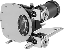
Commonly used in mining, wastewater treatment, and other systems that require large-diameter hose, these pumps have flanged hose connections. They are compatible with chemicals such as cleaning fluids, acid-washing solutions, and detergents. Pumps have a reverse switch that allows flow in either direction. They are self-priming and create suction to draw liquid upward. They can run dry.
Bolt | Overall | |||||||||||||
|---|---|---|---|---|---|---|---|---|---|---|---|---|---|---|
| Flow Rate, gpm | Max. Pressure, psi | Max. Viscosity, cP | Temp. Range, °F | Horsepower | Current, A | Flange OD | Circle Dia. | No. of Holes | Hole Size | Lg. | Wd. | Ht. | Each | |
240V AC/460V AC, Three Phase | ||||||||||||||
Hardwire | ||||||||||||||
| 6 | 217 | 22,000 | 0° to 175° | 3 hp | 3.9/7.8 | 4 1/4" | 3 1/8" | 4 | 0.62" | 26 3/16" | 16 5/8" | 16 7/8" | 00000000 | 000000000 |
Hydraulic Power Units
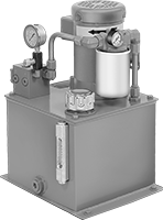
Create and supply hydraulic pressure. Choose a unit with a tank capacity about three times greater than your requirement to allow for heat dissipation. An inlet filter protects the pump from contamination.
All units include an additional NPTF threaded inlet port. NPTF (Dryseal) threads are compatible with NPT threads. UN/UNF (SAE Straight) thread connections have straight threads and are also known as O-ring Boss fittings.
O'all | Inlet Connection— UN/UNF (SAE Straight) | Inlet Connection— NPTF | Outlet Connection— UN/UNF (SAE Straight) | ||||||||||||
|---|---|---|---|---|---|---|---|---|---|---|---|---|---|---|---|
| Max. Flow Rate, gpm | Max. Pressure, psi | Power, hp | Cap., gal. | Lg. | Wd. | Ht. | Thread Size | Dash Size | Pipe Size | Dash Size | Thread Size | Dash Size | Full Load Current | Each | |
240V AC/460V AC, Three Phase | |||||||||||||||
| 2.7 | 1,750 | 3 | 10 | 17 3/8" | 19" | 32 1/2" | 1 1/16"-12 | 12 | 3/4 | 12 | 1 1/16"-12 | 12 | 4.4 A @ 460 V AC | 00000000 | 000000000 |
Portable Air Compressors
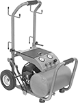
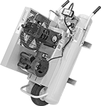
Compressors turn on when the tank falls to the actuation pressure and they turn off when the tank reaches the maximum pressure.
Pressure, psi | Overall | Outlet | ||||||||||||||
|---|---|---|---|---|---|---|---|---|---|---|---|---|---|---|---|---|
| Max. | Actuation | Max. Flow Rate @ psi | hp | Full Load Current, A | Tank Cap., gal. | Volume, dBA | Lg. | Wd. | Ht. | Pipe Size | Thread Type | Gender | Compressor Oil Type | Weight, lbs. | Each | |
Single Tank with Solid Wheels | ||||||||||||||||
Single Phase, 120V AC | ||||||||||||||||
| 140 | 110 | 6.5 cfm @ 90 | 3 | 13.8 | 5.2 | 84 | 19 1/2" | 19" | 29" | 1/4 | NPT | Female | 30W | 88 | 0000000 | 0000000 |
Double Tank with Flat-Free Wheel | ||||||||||||||||
Single Phase, 230V AC | ||||||||||||||||
| 135 | 95 | 10.3 cfm @ 135 11.3 cfm @ 90 | 3 | 15 | 8 | 78 | 43" | 18" | 25" | 3/8 | NPT | Female | 10W-40W | 175 | 000000 | 00000000 |