


Voltage Voltage | Show |
|---|
|
Voltage Voltage | Hide |
|---|
For Use With For Use With |
|---|
|
Power Source Power Source |
|---|
|
Maximum Temperature Maximum Temperature |
|---|
|
Pump Type Pump Type |
|---|
|
Pump Style Pump Style |
|---|
|
Duty Cycle Duty Cycle |
|---|
|
Motor Enclosure Type Motor Enclosure Type |
|---|
|
Current Current |
|---|
Impeller Material Impeller Material |
|---|
|
Maximum Feet of Head Maximum Feet of Head |
|---|
|
Maximum Viscosity Maximum Viscosity |
|---|
|
Priming Type Priming Type |
|---|
|
RoHS (Restriction of Hazardous Substances) RoHS (Restriction ofHazardous Substances) |
|---|
|
REACH (Registration, Evaluation, Authorization and Restriction of Chemicals) REACH (Registration,Evaluation, Authorization and Restriction of Chemicals) |
|---|
|
How to Prime Your Pump
More
How to Determine Feet of Head
More
About Process Pumps
More
About Vacuum Pumps
More
About Drum Pumps
More
About Air Conditioner Cooling Capacity
More
About Sump, Water-Removal, Condensate, and Submersible Pumps
More
About Air Compressors
More
Circulation Pumps for Water and Oil
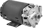
These pumps can be used to move water and lubricating oil in boiler feed systems, cooling towers, and heat exchangers. The housing rotates for vertical or horizontal discharge. They have totally enclosed fan-cooled (TEFC) motors for use in dusty, dirty, and damp environments. Pumps are gravity fed and require an elevated liquid source to fully fill the pump before turning on. Do not run dry.
Note: If flow control is needed, place valves or reducers on the discharge side; never restrict the inlet of a pump with a valve or reducer.
![]() For technical drawings and 3-D models, click on a part number.
For technical drawings and 3-D models, click on a part number.
Flow Rate, gpm | Intake (NPT) | Discharge (NPT) | Overall | |||||||||||||||||
|---|---|---|---|---|---|---|---|---|---|---|---|---|---|---|---|---|---|---|---|---|
| Max. Flow Rate, gpm | @ 10 ft. of Head | @ 20 ft. of Head | @ 30 ft. of Head | @ 40 ft. of Head | @ 50 ft. of Head | Max. ft. of Head | Max. Pressure, psi | Max. Viscosity, cP | Motor Enclosure Type | hp | Current, A | Pipe Size | Gender | Pipe Size | Gender | Lg. | Wd. | Ht. | Each | |
120/230V AC, Single Phase—With Thermal Overload Protection | ||||||||||||||||||||
Hardwire | ||||||||||||||||||||
| 47 | 42 | 34 | 25 | 10 | __ | 45 | 75 | 20 | Totally Enclosed Fan Cooled | 1/2 | 9/5 | 1 | Female | 3/4 | Female | 13" | 8 3/4" | 8 5/8" | 0000000 | 0000000 |
| 79 | 72 | 63 | 51 | 35 | 5 | 52 | 75 | 20 | Totally Enclosed Fan Cooled | 1 1/2 | 18/9 | 1 1/4 | Female | 1 | Female | 14 1/4" | 8 3/4" | 8 5/8" | 0000000 | 000000 |
| Replacement Seal Assembly | 00000000 | Each | 000000 |
Constant-Flow-Rate Pumps for Water
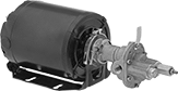
Also known as gear pumps, these produce a smooth flow of liquid for applications such as cooling engines, powering hydraulic equipment, and extracting liquid from holding tanks. Pumps are self-priming after you fill the pump chamber with liquid. As liquid in the chamber is expelled, a suction force is created which allows the pump to draw liquid upward. Do not use with solids.
Pumps with a totally enclosed (TE) or totally enclosed fan-cooled (TEFC) motor can be used in dusty, dirty, and damp environments.
Pumps that cannot be sold to Canada are restricted by local energy efficiency requirements.
Note: Pumps must be filled with liquid before use. They need a constant flow of liquid and cannot run dry. If flow control is needed, place valves or reducers on the discharge side; never restrict the inlet of a pump with a valve or reducer.
![]() For technical drawings and 3-D models, click on a part number.
For technical drawings and 3-D models, click on a part number.
Intake (NPT) | Discharge (NPT) | Overall | ||||||||||||||
|---|---|---|---|---|---|---|---|---|---|---|---|---|---|---|---|---|
| Max. Flow Rate, gpm | Discharge Pressure, psi | Max. Viscosity, cP | Temp. Range, °F | hp | Current, A | Pipe Size | Gender | Pipe Size | Gender | Motor Enclosure Type | Lg. | Wd. | Ht. | Cannot Be Sold To | Each | |
115/230V AC, Single Phase—Without Thermal Overload Protection | ||||||||||||||||
Hardwire | ||||||||||||||||
| 2.1 | 150 | 100,000 | 32° to 140° | 1/2 | 7.4/3.7 | 1/4 | Female | 1/4 | Female | Totally Enclosed | 16 1/16" | 8 3/16" | 8" | __ | 0000000 | 000000000 |
| 8.5 | 150 | 100,000 | 32° to 140° | 1 | 12.8/6.4 | 1/2 | Female | 1/2 | Female | Totally Enclosed | 18 1/8" | 9 3/16" | 9" | __ | 0000000 | 00000000 |
230/460V AC, Three Phase—Without Thermal Overload Protection | ||||||||||||||||
Hardwire | ||||||||||||||||
| 10.2 | 150 | 100,000 | 32° to 140° | 1 1/2 | 4.4/2.2 | 1/2 | Female | 1/2 | Female | Totally Enclosed Fan Cooled | 19 13/16" | 9 5/16" | 7 1/4" | Canada | 0000000 | 00000000 |
| 23 | 150 | 100,000 | 32° to 140° | 3 | 8.4/4.2 | 1 | Female | 1 | Female | Totally Enclosed Fan Cooled | 25 1/8" | 10 5/16" | 9 1/16" | Canada | 0000000 | 00000000 |
Sanitary Electric Drum Pumps
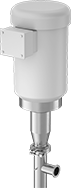
Commonly used in food, beverage, pharmaceutical, and cosmetic processing, these pumps are designed for sanitary environments. The discharge connection can be easily disassembled for cleaning. Pumps do not include a drum connector.
Pumps with a maximum viscosity of 100,000 cP handle a wide range of liquid thicknesses from water up to lotions and pie fillings.
![]() For technical drawings and 3-D models, click on a part number.
For technical drawings and 3-D models, click on a part number.
Temp. Range, °F | Intake | Discharge | |||||||||||||
|---|---|---|---|---|---|---|---|---|---|---|---|---|---|---|---|
| Flow Rate, gpm | Discharge Pressure, psi | For Container Size, gal. | Max. Viscosity, cP | Min. | Max. | Horsepower | Current, A | For Drum Opening Size, mm | Tube OD | Tube Lg. | Tube Connection Type | For Tube OD | Thermal Protection | Each | |
190V AC, 380V AC, 230V AC, 460V AC; Three Phase—Hardwire | |||||||||||||||
Aluminum Housing | |||||||||||||||
| 7 | 87 | 55 | 100,000 | 15° | 300° | 1 1/2 hp | 6.4, 3.2, 5.8, 2.9 | 50 | 2" | 39" | Quick Clamp | 1 1/2" | Without Thermal Overload Protection | 0000000 | 000000000 |
Sump Pumps without Float Switch for Sewage Water
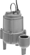
Pumps activate when plugged in. You can add a plug-in switch to control when the pump activates. Equipped with a large intake and rugged impeller, these pumps transfer raw sewage water with solids up to 2" in diameter. They have a cast iron housing that stands up to demanding environments. Submerge while in use and do not run dry.
Max. Flow Rate, gpm | Discharge | Min. Sump Pit | Overall | |||||||||||||||
|---|---|---|---|---|---|---|---|---|---|---|---|---|---|---|---|---|---|---|
| @ 5 Ft. of Head | @ 10 Ft. of Head | @ 15 Ft. of Head | Max. Ft. of Head, ft. | Max. Solids Dia. | Temp. Range, °F | Horsepower | Current, A | Intake Inlet Connection Type | Pipe Size | Thread Type | Gender | Dia. | Dp. | Ht. | Wd. | Lg. | Each | |
208/230V AC, Single Phase—With Thermal Overload Protection | ||||||||||||||||||
Plug with 20 ft. Cord | ||||||||||||||||||
| 120 | 100 | 80 | 25 | 2" | 35° to 140° | 1/2 hp | 5.5 | Open | 2 | NPT | Female | 18" | 24" | 14" | 8.6" | 10.4" | 00000000 | 0000000 |
Oil-Free Electric Vacuum Pumps
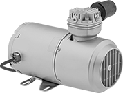
Since these pumps don't require lubrication, there’s no risk of oil contamination. Maximum flow rate is the rate at which air is pumped before a vacuum is created. Flow rate steadily decreases as the pump generates the vacuum. The larger the tank, the longer it will take to form a vacuum.
Style C pumps withstand harsh operating conditions. Use to service machinery and refrigeration and circulation systems.
Intake | Discharge | O'all | |||||||||||||||
|---|---|---|---|---|---|---|---|---|---|---|---|---|---|---|---|---|---|
| Style | Max. Vacuum, in. of Hg | Max. Flow Rate, cfm | Temp. Range, °F | Volume, dBA | Horsepower | Current, A | Pipe Size | Thread Type | Gender | Pipe Size | Thread Type | Gender | Lg. | Wd. | Ht. | Each | |
NEMA 5-15 Plug | |||||||||||||||||
| C | 27.5 | 5 | 35° to 100° | 75 | 1/2 hp | 6/12 | 1/4 | NPT | Female | 1/4 | NPT | Female | 13 1/4" | 12 3/8" | 9" | 000000 | 000000000 |
Hardwire | |||||||||||||||||
| C | 27.5 | 10.5 | 35° to 100° | 75 | 1 1/2 hp | 10/21 | 1/4 | NPT | Female | 1/4 | NPT | Female | 21" | 12 1/4" | 8 1/2" | 000000 | 00000000 |
Electric Vacuum Pumps
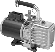
Use these pumps in applications such as degassing and servicing refrigeration and freezer systems. Maximum flow rate is the rate at which air is pumped before a vacuum is created. Flow rate steadily decreases as the pump generates the vacuum. The larger the tank, the longer it will take to form a vacuum. Tube and fitting ID will also affect flow.
Intake | Discharge | Overall | |||||||||||||||
|---|---|---|---|---|---|---|---|---|---|---|---|---|---|---|---|---|---|
| Max. Vacuum | Max. Flow Rate, cfm | Temp. Range, °F | Volume, dBA | Horsepower | Current, A | Port Size | Tube Connection Type | Gender | Pipe Size | Thread Type | Gender | Lg. | Wd. | Ht. | Oil Capacity, oz. | Each | |
115V AC/230V AC, Single Phase—With Thermal Overload Protection | |||||||||||||||||
NEMA 6-15 Plug | |||||||||||||||||
| 1.5×10 -2 torr @ 72° F | 3 | 30° to 180° | 70 | 1/2 hp | 3.5/7 | 1/4", 3/8", 1/2" | Flared | Male | 1/2 | NPT | Male | 14 1/2" | 5 5/8" | 12" | 27 | 0000000 | 0000000 |
| 1.5×10 -2 torr @ 72° F | 5 | 30° to 180° | 70 | 1/2 hp | 3.5/7 | 1/4", 3/8", 1/2" | Flared | Male | 1/2 | NPT | Male | 14 1/2" | 5 5/8" | 12" | 21 | 0000000 | 000000 |
| 1.5×10 -2 torr @ 72° F | 7 | 30° to 180° | 70 | 1/2 hp | 3.5/7 | 1/4", 3/8", 1/2" | Flared | Male | 1/2 | NPT | Male | 14 1/2" | 5 5/8" | 12" | 21 | 0000000 | 000000 |
| 1.5×10 -2 torr @ 72° F | 10 | 30° to 180° | 70 | 1/2 hp | 3.5/7 | 1/4", 3/8", 1/2" | Flared | Male | 1/2 | NPT | Male | 16" | 5 5/8" | 12" | 26 | 0000000 | 000000 |
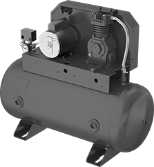
Air Compressors
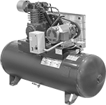
Compressors turn on when the tank falls to the actuation pressure and they turn off when the tank reaches the maximum pressure.
Pressure, psi | Output (Female) | Overall | |||||||||||
|---|---|---|---|---|---|---|---|---|---|---|---|---|---|
| Max. | Actuation | Max. Flow Rate @ psi | hp | Full Load Current, A | Tank Cap., gal. | Vol., dBA | Pipe Size | Thread Type | Lg. | Wd. | Ht. | Each | |
Horizontal | |||||||||||||
Electric Powered | |||||||||||||
Single Phase, 230V AC | |||||||||||||
| 175 | 135 | 17.2 cfm @ 175 18 cfm @ 100 18 cfm @ 75 | 5 | 28 | 80 | 78 | 3/4 | NPT | 70" | 23" | 47" | 000000 | 000000000 |
| 175 | 135 | 22.6 cfm @ 175 24 cfm @ 100 24 cfm @ 75 | 7 1/2 | 40 | 80 | 79.7 | 3/4 | NPT | 70" | 23" | 47" | 000000 | 00000000 |
Three Phase, 230V AC | |||||||||||||
| 175 | 135 | 17.2 cfm @ 175 18 cfm @ 100 18 cfm @ 75 | 5 | 15.2 | 80 | 78 | 3/4 | NPT | 70" | 23" | 47" | 0000000 | 00000000 |
| 175 | 135 | 22.6 cfm @ 175 24 cfm @ 100 24 cfm @ 75 | 7 1/2 | 22 | 80 | 79.7 | 3/4 | NPT | 70" | 23" | 47" | 0000000 | 00000000 |
| 175 | 135 | 35 cfm @ 175 36 cfm @ 100 36 cfm @ 75 | 10 | 28 | 120 | 86.4 | 1 | NPT | 78" | 28" | 55" | 0000000 | 00000000 |
Vertical | |||||||||||||
Electric Powered | |||||||||||||
Single Phase, 230V AC | |||||||||||||
| 175 | 135 | 17.2 cfm @ 175 18 cfm @ 100 18 cfm @ 75 | 5 | 28 | 80 | 78 | 3/4 | NPT | 37" | 24" | 74" | 0000000 | 00000000 |
| 175 | 135 | 22.6 cfm @ 175 24 cfm @ 100 24 cfm @ 75 | 7 1/2 | 40 | 80 | 79.7 | 3/4 | NPT | 37" | 24" | 74" | 0000000 | 00000000 |
Three Phase, 230V AC | |||||||||||||
| 175 | 135 | 17.2 cfm @ 175 18 cfm @ 100 18 cfm @ 75 | 5 | 15.2 | 80 | 78 | 3/4 | NPT | 37" | 24" | 74" | 00000000 | 00000000 |
| 175 | 135 | 22.6 cfm @ 175 24 cfm @ 100 24 cfm @ 75 | 7 1/2 | 22 | 80 | 79.7 | 3/4 | NPT | 37" | 24" | 74" | 00000000 | 00000000 |
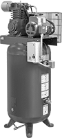
Fire Sprinkler Air Compressors
Pressurize air for sprinkler systems. These compressors turn on when the tank falls to the activation pressure and they turn off when the tank reaches the maximum pressure. UL and C-UL listed, as well as CSA and CSA-US certified, they meet U.S. and Canadian safety standards.
![]() For technical drawings and 3-D models, click on a part number.
For technical drawings and 3-D models, click on a part number.
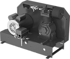
Air Compressors | ||||||||||||||||
|---|---|---|---|---|---|---|---|---|---|---|---|---|---|---|---|---|
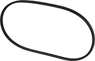
Pressure, psi | Outlet | Overall | Replacement Drive Belts | |||||||||||||
| Maximum | Actuation | Maximum Flow Rate | hp | Full Load Current, A | Tank Capacity, gal. | Volume, dB | Pipe Size | Thread Type | Gender | Length | Width | Height | Each | Each | ||
Single Phase, 120V AC/230V AC | ||||||||||||||||
| 40 | 30 | 7.4 cfm @ 40 psi | 1 | 12.5 | 30 | 77 | 1/2 | NPT | Female | 39" | 16 1/2" | 34 1/4" | 00000000 | 000000000 | 00000000 | 000000 |
| 40 | 30 | 10.9 cfm @ 40 psi | 1 1/2 | 15.8 | 30 | 77 | 1/2 | NPT | Female | 39" | 16 1/2" | 34 1/4" | 00000000 | 00000000 | 00000000 | 00000 |
| 40 | 30 | 12.4 cfm @ 40 psi | 2 | 21.6 | 30 | 77 | 1/2 | NPT | Female | 39" | 16 1/2" | 34 1/4" | 00000000 | 00000000 | 00000000 | 00000 |
Portable Air Compressors
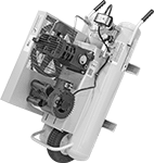
Compressors turn on when the tank falls to the actuation pressure and they turn off when the tank reaches the maximum pressure.
Pressure, psi | Overall | Outlet | ||||||||||||||
|---|---|---|---|---|---|---|---|---|---|---|---|---|---|---|---|---|
| Max. | Actuation | Max. Flow Rate @ psi | hp | Full Load Current, A | Tank Cap., gal. | Volume, dBA | Lg. | Wd. | Ht. | Pipe Size | Thread Type | Gender | Compressor Oil Type | Weight, lbs. | Each | |
Double Tank with Flat-Free Wheel | ||||||||||||||||
Single Phase, 230V AC | ||||||||||||||||
| 135 | 95 | 10.3 cfm @ 135 11.3 cfm @ 90 | 3 | 15 | 8 | 78 | 43" | 18" | 25" | 3/8 | NPT | Female | 10W-40W | 175 | 000000 | 000000000 |
Combination Air Conditioners/Heaters
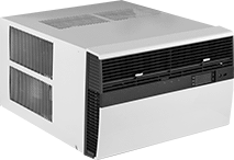
Be comfortable year-round with units that cool and heat your space. Adjust the louvers to direct airflow. The higher the combined energy efficiency ratio, the more energy efficient the unit. Your operating costs will depend on your utility rates and use. The estimated yearly energy cost is based on electricity cost of $0.12 per kWh. For more information, visit www.ftc.gov/energy.
These air conditioners/heaters come ready for through-the-wall installation. Optional window mounting kits (sold separately) can be used to mount units in a 27 3/8" to 42" wide window or 29 7/8" to 42" wide window.
Overall | For Opening | ||||||||||||||
|---|---|---|---|---|---|---|---|---|---|---|---|---|---|---|---|
| Cooling Cap., Btu/hr. | Heat Output, Btu/hr. | Combined Energy Efficiency Ratio | Max. Area Heated @ Temp. Change | Estimated Yearly Energy Cost | Airflow, cfm | Current, A | Plug Style | Ht. | Wd. | Dp. | Ht. | Wd. | For Max. Wall Thick. | Each | |
With Adjustable Thermostat (60° to 90° F) | |||||||||||||||
208-230V AC, Single Phase—Three Prong Plug | |||||||||||||||
| 12,000 | 10,700 | 10.9 | 1,420 cu. ft. @ 10° F 350 cu. ft. @ 40° F 470 cu. ft. @ 30° F 710 cu. ft. @ 20° F | $107 | 325 | 4.9, 16 | NEMA 6-20 | 15 15/16" | 25 15/16" | 29" | 16 3/16" | 26 3/16" | 7 3/8" | 00000000 | 000000000 |
| 20,000 | 13,000 | 10.3 | 1,730 cu. ft. @ 10° F 430 cu. ft. @ 40° F 570 cu. ft. @ 30° F 860 cu. ft. @ 20° F | $189 | 425 | 10.2, 19.5 | NEMA 6-30 | 17 15/16" | 25 15/16" | 29" | 18 3/16" | 26 3/16" | 7 3/8" | 00000000 | 00000000 |
| 23,000 | 17,300 | 10.3 | 1,022 cu. ft. @ 30° F 1,533 cu. ft. @ 20° F 3,066 cu. ft. @ 10° F 767 cu. ft. @ 40° F | $225 | 750 | 11.1, 24 | NEMA 6-30 | 20 3/16" | 28" | 35 1/2" | 20 3/8" | 28 1/4" | 15 1/8" | 00000000 | 00000000 |
| Optional Window Mounting Kit for Air Conditioner/Heater with 20,000 Btu/hr. Cooling Cap. | 00000000 | Each | 000000 |
| Optional Window Mounting Kit for Air Conditioner/Heater with 12,000 Btu/hr. Cooling Cap. | 00000000 | Each | 00000 |
| Optional Window Mounting Kit for Air Conditioner/Heater with 23,000 Btu/hr. Cooling Cap. | 00000000 | Each | 00000 |