Filter by
System of Measurement
Fitting Type
For Use With
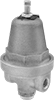
Outlet Pressure
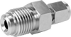
Connects To
Tube Material
Maximum Inlet Pressure
U.S.–Mexico–Canada Agreement (USMCA) Qualifying
Maximum Temperature
Minimum Temperature
DFARS Specialty Metals
Fluid Handling

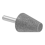 Abrading & Polishing
 Building & Grounds
 Electrical & Lighting
 Fabricating
 Fastening & Joining
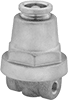
 Filtering
 Flow & Level Control
 Furniture & Storage
 Hand Tools
 Hardware
 Heating & Cooling
 Lubricating
 Material Handling
 Measuring & Inspecting
 Office Supplies & Signs
 Pipe, Tubing, Hose & Fittings
 Plumbing and Janitorial
 Power Transmission
 Pressure & Temperate Control
 Pulling & Lifting
 Raw Materials
 Safety Supplies
 Sawing & Cutting
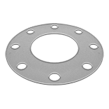 Sealing
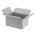 Shipping
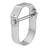 Suspending