Filter by
For Use With
System of Measurement
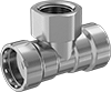
Fitting Type
Connects To
Fitting Connection
DFARS Specialty Metals
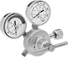
Maximum Inlet Pressure
Inlet Pipe Size
U.S.–Mexico–Canada Agreement (USMCA) Qualifying
REACH
Export Control Classification Number (ECCN)
Pipe Schedule

Pipe Material
Compatible With
Tee Type

Finish
Certification
For Flange Class