


System of Measurement System of Measurement |
|---|
|
Thread Size Thread Size | Show |
|---|
Thread Size Thread Size | Hide |
|---|
Thread Type Thread Type |
|---|
Material Material |
|---|
|
Type Type |
|---|
| Reducer | |
For Tap Thread Size For Tap Thread Size |
|---|
Threaded Insert Type Threaded Insert Type |
|---|
| Thread Locking | Key Locking |
| Helical |
Connection Style Connection Style |
|---|
 |
| Flared |

Flared Angle Flared Angle |
|---|
|
Flared Connection Type Flared Connection Type |
|---|
 | Standard |
Thread Direction Thread Direction |
|---|
 |  |
| Right Hand | Left Hand |
Specifications Met Specifications Met |
|---|
|
For Use With For Use With |
|---|
|
|
RoHS (Restriction of Hazardous Substances) RoHS (Restriction ofHazardous Substances) |
|---|
|
DFARS (Defense Acquisition Regulations Supplement) DFARS (Defense AcquisitionRegulations Supplement) |
|---|
For Minimum Material Thickness For MinimumMaterial Thickness |
|---|
|
For Maximum Hole Diameter For Maximum Hole Diameter |
|---|
|
REACH (Registration, Evaluation, Authorization and Restriction of Chemicals) REACH (Registration,Evaluation, Authorization and Restriction of Chemicals) |
|---|
|
How to Identify and Measure Fittings
Pipe size is an industry designation, not the actual size. View information about how to measure threaded and unthreaded pipe and pipe fittings.
More
About Nuts, Materials, and Finishes
More
How to Install Key-Locking Inserts
More
How to Install Helical Inserts
More
About Helical Insert Length
More
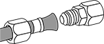
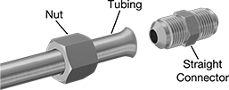
45° Flared Fittings for Copper and Brass Tubing
- Temperature Range: -65° to 250° F
- Tubing: Use with seamless brass and copper that meets ASTM B280
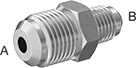
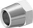
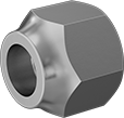
No sleeve is required to assemble these fittings, which makes for a faster, more convenient installation compared to 37° flared fittings. They require a nut (sold separately) for each tube end. Fittings are also known as refrigeration and SAE fittings. They are brass for good corrosion resistance.
Copper tube size is the accepted designation of the copper tubing industry, not the actual tube OD.
![]() For technical drawings and 3-D models, click on a part number.
For technical drawings and 3-D models, click on a part number.
- For Use With: Air, Cutting Oil, Diesel Fuel, Fuel Oil, Mineral Oil, Refrigerant, Water
- Specifications Met: SAE J512, SAE J513, UL Listed
- For Use With: Air, Cutting Oil, Diesel Fuel, Fuel Oil, Mineral Oil, Refrigerant, Water; except nuts for 1" tube OD are not for use with fuel oil
- Specifications Met: SAE J512, SAE J513, UL Listed; except nuts for 1" tube OD meet SAE J512 and SAE J513 only
For Tube | |||||||
|---|---|---|---|---|---|---|---|
| OD | Wall Thick. | Nut Material | Max. Pressure | Lg. | Each | ||
Short Nuts | |||||||
| A | 1/4" | 0.049" | Brass | 1,400 psi @ 72° F | 3/4" | 000000000 | 00000 |
| A | 5/16" | 0.049" | Brass | 1,200 psi @ 72° F | 7/8" | 000000000 | 0000 |
| A | 3/8" | 0.032" | Brass | 1,000 psi @ 72° F | 29/32" | 000000000 | 0000 |
| A | 3/8" | 0.065" | Brass | 1,000 psi @ 72° F | 1" | 000000000 | 0000 |
| A | 1/2" | 0.032" | Brass | 750 psi @ 72° F | 1" | 000000000 | 0000 |
| A | 1/2" | 0.083" | Brass | 750 psi @ 72° F | 1 1/8" | 000000000 | 0000 |
| A | 5/8" | 0.035" | Brass | 650 psi @ 72° F | 1 1/16" | 000000000 | 00000 |
| A | 5/8" | 0.095" | Brass | 650 psi @ 72° F | 1 5/16" | 000000000 | 00000 |
| B | 1/4" | 0.03" | Brass | 1,400 psi @ 72° F | 5/8" | 00000000 | 0000 |
| B | 1/4" | 0.03" | Brass | 1,400 psi @ 72° F | 23/32" | 000000000 | 00000 |
| B | 5/16" | 0.032" | Brass | 1,200 psi @ 72° F | 21/32" | 000000000 | 00000 |
| B | 3/8" | 0.032" | Brass | 1,000 psi @ 72° F | 27/32" | 000000000 | 00000 |
| B | 1/2" | 0.032" | Brass | 750 psi @ 72° F | 27/32" | 000000000 | 0000 |
| B | 5/8" | 0.035" | Brass | 650 psi @ 72° F | 31/32" | 000000000 | 00000 |
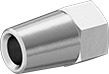
Long Nuts | |||||||
| A | 1/4" | 0.049" | Brass | 1,400 psi @ 72° F | 15/16" | 000000000 | 0000 |
| A | 5/16" | 0.049" | Brass | 1,200 psi @ 72° F | 1 1/8" | 000000000 | 0000 |
| A | 3/8" | 0.065" | Brass | 1,000 psi @ 72° F | 1 5/16" | 000000000 | 0000 |
| A | 1/2" | 0.083" | Brass | 750 psi @ 72° F | 1 5/8" | 000000000 | 00000 |
| A | 5/8" | 0.095" | Brass | 650 psi @ 72° F | 1 7/8" | 000000000 | 00000 |
| B | 1/4" | 0.03" | Brass | 1,400 psi @ 72° F | 15/16" | 000000000 | 00000 |
| B | 3/8" | 0.032" | Brass | 1,000 psi @ 72° F | 1 1/16" | 000000000 | 00000 |
| B | 1/2" | 0.032" | Brass | 750 psi @ 72° F | 1 3/16" | 000000000 | 00000 |
Inch-to-Inch Female Hex Thread Adapters
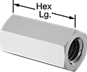
Connect two differently sized male-threaded parts, such as threaded rods, and tighten with a standard wrench. The threads on these adapters have various sizes and spacing, so you can increase or decrease thread size or adapt from coarse to fine threading. You can also use them to change the gender of a connection from male to female. Small adapters can work as threaded standoffs, which position and separate circuit boards and other components in assemblies.
18-8 stainless steel adapters withstand wet environments but will corrode when exposed to salt water and other chloride solutions.
316 stainless steel adapters are ideal in wet environments and will not corrode when exposed to salt water or harsh chemicals.
Aluminum adapters are about one third of the weight of steel adapters and resist corrosion in wet environments.
Adapters that meet ASTM specifications are made from or plated with materials that adhere to standards for chemical and physical properties, such as hardness.
![]() For technical drawings and 3-D models, click on a part number.
For technical drawings and 3-D models, click on a part number.
Thread Size | Thread Lg. | Thread Fit | Hex | Each | ||||||||
|---|---|---|---|---|---|---|---|---|---|---|---|---|
| (A) | (B) | (A) | (B) | (A) | (B) | Size | Lg. | Specifications Met | Hardness | 1-9 | 10-Up | |
18-8 Stainless Steel | ||||||||||||
| 5/8"-11 | 5/8"-18 | 5/8" | 5/8" | Class 2B | Class 2B | 7/8" | 2" | ASTM A582 | Rockwell B80 | 000000000 | 000000 | 000000 |
316 Stainless Steel | ||||||||||||
| 5/8"-11 | 5/8"-18 | 5/8" | 5/8" | Class 2B | Class 2B | 7/8" | 2" | ASTM A276 | Rockwell B83 | 000000000 | 00000 | 00000 |
Aluminum | ||||||||||||
| 5/8"-11 | 5/8"-18 | 5/8" | 5/8" | Class 2B | Class 2B | 7/8" | 2" | ASTM B211 | Rockwell B56 | 000000000 | 0000 | 0000 |
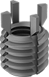
18-8 Stainless Steel Easy-to-Install Thread-Locking Inserts
Made of 18-8 stainless steel, these inserts have good corrosion resistance. Also known as E-Z Lok, they use Loctite® adhesive to keep them in place. The adhesive reaches full strength after 72 hours. They may be mildly magnetic. Installation requires a drill bit and a standard tap. Then set the insert with an installation bit, a slotted screwdriver, or a bolt with two nuts.
Inserts with a thin wall are often used in small holes or near the edge of a workpiece.
![]() For technical drawings and 3-D models, click on a part number.
For technical drawings and 3-D models, click on a part number.

Black-Phosphate Steel Easy-to-Install Thread-Locking Inserts
A black-phosphate finish provides mild corrosion resistance. Also known as E-Z Lok, these inserts use Loctite® adhesive to keep them in place. The adhesive reaches full strength after 72 hours. Installation requires a drill bit and a standard tap. Then set the insert with a bolt and two nuts, or use an installation bit.
Choose inserts with a thick wall for greater strength than thin-wall inserts, or to fill a large hole.
To drive slotted inserts, you can use a slotted screwdriver instead of using an installation bit or a bolt and two nuts.
![]() For technical drawings and 3-D models, click on a part number.
For technical drawings and 3-D models, click on a part number.

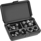
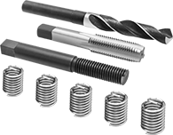
Easy-to-Install Thread-Locking Insert Assortments
These assortments include various sizes of thread-locking inserts. Also known as E-Z Lok, they use Loctite® adhesive to keep them in place. The adhesive reaches full strength after 72 hours. All inserts have thick walls for strength and can be used to fill a large hole.
Black-phosphate steel inserts are mildly corrosion resistant.
![]() For technical drawings and 3-D models, click on a part number.
For technical drawings and 3-D models, click on a part number.
For Tap | |||||||
|---|---|---|---|---|---|---|---|
| Includes | No. of Inserts Included | Thread Size | Drill Bit Size | For Max. Hole Dia. | Drive Style | Each | |
Inch Assortments | |||||||
Black-Phosphate Steel | |||||||
| 1/2"-20 Thread × 0.656" Installed Lg. (6 Each) 5/8"-18 Thread × 0.688" Installed Lg. (7 Each) 3/4"-16 Thread × 0.781" Installed Lg. (7 Each) 1"-14 Thread × 1 1/4" Installed Lg. (2 Each) | 22 | 3/4"-10 7/8"-9 1"-8 1 3/8"-12 | 21/32" 49/64" 7/8" 1 9/32" | 21/32" 49/64" 7/8" 1 9/32" | Slotted | 000000000 | 000000 |
For fast installation, use these installation bits with power drills and drill presses.
18-8 Stainless Steel Key-Locking Inserts
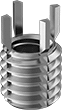
Made of stainless steel, these inserts have good corrosion resistance. Drive the keys into the surrounding material for a more secure hold than thread-locking inserts. Use them to repair or change threads in soft metals such as aluminum. Inserts may be mildly magnetic. They’re comparable to Keensert® inserts. Installation requires a drill bit, a standard tap, an installation tool, and a hammer.
Choose inserts with a thick wall for greater strength than thin-wall inserts, or to fill a large hole.
Inserts with an extra-thick wall are stronger than thick- and thin-wall inserts. Use them to reduce the size of tapped holes.
![]() For technical drawings and 3-D models, click on a part number.
For technical drawings and 3-D models, click on a part number.
Inserts | ||||||||||
|---|---|---|---|---|---|---|---|---|---|---|
Each | Installation Tools | |||||||||
| Thread Size | For Tap Thread Size | Installed Lg. | Drill Bit Size | For Max. Hole Dia. | No. of Locking Keys | 1-9 | 10-Up | Each | ||
18-8 Stainless Steel with Thick Wall | ||||||||||
| 5/8"-18 | 7/8"-14 | 7/8" | 53/64" | 0.828" | 4 | 000000000 | 000000 | 000000 | 000000000 | 000000 |
18-8 Stainless Steel with Extra Thick Wall | ||||||||||
| 5/8"-18 | 1"-12 | 7/8" | 15/16" | 0.938" | 4 | 000000000 | 00000 | 00000 | 000000000 | 00000 |
Black-Phosphate Steel Key-Locking Inserts
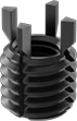
A black-phosphate finish provides mild corrosion resistance. Drive the keys into the surrounding material for a more secure hold than thread-locking inserts. Use them to repair or change threads in soft metals such as aluminum. They’re comparable to Keensert® inserts. Installation requires a drill bit, a standard tap, an installation tool, and a hammer.
Choose inserts with a thick wall for greater strength than thin-wall inserts, or to fill a large hole with stripped threads.
Inserts with an extra thick wall are stronger than thick- and thin-wall inserts. Use them to reduce the size of tapped holes.
![]() For technical drawings and 3-D models, click on a part number.
For technical drawings and 3-D models, click on a part number.
Inserts | ||||||||||
|---|---|---|---|---|---|---|---|---|---|---|
Each | Installation Tools | |||||||||
| Thread Size | For Tap Thread Size | Installed Lg. | Drill Bit Size | For Max. Hole Dia. | No. of Locking Keys | 1-9 | 10-Up | Each | ||
Black-Phosphate Steel with Thick Wall | ||||||||||
| 5/8"-18 | 7/8"-14 | 7/8" | 53/64" | 53/64" | 4 | 000000000 | 00000 | 00000 | 000000000 | 000000 |
Black-Phosphate Steel with Extra Thick Wall | ||||||||||
| 5/8"-18 | 1"-12 | 7/8" | 15/16" | 15/16" | 4 | 000000000 | 00000 | 00000 | 000000000 | 00000 |
Mil. Spec. Stainless Steel Key-Locking Inserts
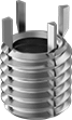
These inserts are made to stringent military specifications. Drive the keys into the surrounding material for a more secure hold than thread-locking inserts. Use them to repair or change threads in soft metals such as aluminum. Inserts may be mildly magnetic. They’re comparable to Keensert® inserts. Installation requires a drill bit, a standard tap, an installation tool, and a hammer.
Choose inserts with a thick wall for greater strength than thin-wall inserts, or to fill a large hole.
![]() For technical drawings and 3-D models, click on a part number.
For technical drawings and 3-D models, click on a part number.
Inserts | Installation Tools | |||||||||
|---|---|---|---|---|---|---|---|---|---|---|
| Thread Size | For Tap Thread Size | Installed Lg. | Drill Bit Size | For Max. Hole Dia. | No. of Locking Keys | Specifications Met | Each | Each | ||
303 Stainless Steel with Thick Wall | ||||||||||
| 5/8"-18 | 7/8"-14 | 7/8" | 53/64" | 0.833" | 4 | MS51831-208, NAS1395C10 | 000000000 | 000000 | 000000000 | 000000 |
| 5/8"-18 | 1"-12 | 7/8" | 15/16" | 0.942" | 4 | MS51832-208 | 000000000 | 00000 | 000000000 | 00000 |
Mil. Spec. Alloy Steel Key-Locking Inserts
The strongest key-locking inserts we offer, these inserts are made to stringent military specifications. Drive the keys into the surrounding material for a more secure hold than thread-locking inserts. Use them to repair or change threads in soft metals such as aluminum. Inserts may be mildly magnetic. They’re comparable to Keensert® inserts. Installation requires a drill bit, a standard tap, an installation tool, and a hammer.
Choose inserts with a thick wall for greater strength than thin-wall inserts, or to fill a large hole.
![]() For technical drawings and 3-D models, click on a part number.
For technical drawings and 3-D models, click on a part number.
Key-Locking Insert Assortments with Installation Tool
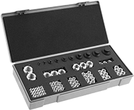
These assortments include various sizes of key-locking inserts with thick and thin walls, and an installation tool. Drive the keys into the surrounding material for a more secure hold than thread-locking inserts. Use them to repair or convert threads in soft metals such as aluminum. They’re comparable to Keensert® inserts.
18-8 stainless steel inserts are more corrosion resistant than black-phosphate steel. They may be mildly magnetic.
Black-phosphate steel inserts are mildly corrosion resistant.
Choose assortments with thick-wall inserts for greater strength than thin-wall inserts, or to fill a large hole.
![]() For technical drawings and 3-D models, click on a part number.
For technical drawings and 3-D models, click on a part number.
For Tap | ||||||
|---|---|---|---|---|---|---|
| Includes | No. of Inserts Included | Thread Size | Drill Bit Size | For Max. Hole Dia. | Each | |
Inch | ||||||
18-8 Stainless Steel with Thick Wall | ||||||
| 1/4"-28 Thread × 3/8" Installed Lg. (20 Each) 5/16"-24 Thread × 0.438" Installed Lg. (15 Each) 3/8"-24 Thread × 1/2" Installed Lg. (10 Each) 7/16"-20 Thread × 5/8" Installed Lg. (10 Each) 1/2"-20 Thread × 5/8" Installed Lg. (6 Each) 9/16"-18 Thread × 0.813" Installed Lg. (5 Each) 5/8"-18 Thread × 7/8" Installed Lg. (3 Each) 3/4"-16 Thread × 1 1/8" Installed Lg. (3 Each) 7/8"-14 Thread × 1 1/4" Installed Lg. (3 Each) 1"-12 Thread × 1 3/8" Installed Lg. (2 Each) Installation Tool | 77 | 7/16"-14 1/2"-13 9/16"-12 5/8"-11 3/4"-16 7/8"-14 1 1/8"-12 1 1/4"-12 1 3/8"-12 | X 29/64" 33/64" 37/64" 45/64" 53/64" 1 1/16" 1 3/16" 1 5/16" | 0.397" 29/64" 33/64" 37/64" 45/64" 53/64" 1 1/16" 1 3/16" 1 5/16" | 000000000 | 0000000 |
Black-Phosphate Steel with Thick Wall | ||||||
| 1/4"-28 Thread × 3/8" Installed Lg. (20 Each) 5/16"-24 Thread × 0.438" Installed Lg. (15 Each) 3/8"-24 Thread × 1/2" Installed Lg. (10 Each) 7/16"-20 Thread × 5/8" Installed Lg. (10 Each) 1/2"-20 Thread × 5/8" Installed Lg. (6 Each) 9/16"-18 Thread × 0.813" Installed Lg. (5 Each) 5/8"-18 Thread × 7/8" Installed Lg. (3 Each) 3/4"-16 Thread × 1 1/8" Installed Lg. (3 Each) 7/8"-14 Thread × 1 1/4" Installed Lg. (3 Each) 1"-12 Thread × 1 3/8" Installed Lg. (2 Each) Installation Tool | 77 | 7/16"-14 1/2"-13 9/16"-12 5/8"-11 3/4"-16 7/8"-14 1 1/8"-12 1 1/4"-12 1 3/8"-12 | X 29/64" 33/64" 37/64" 45/64" 53/64" 1 1/16" 1 3/16" 1 5/16" | 0.397" 29/64" 33/64" 37/64" 45/64" 53/64" 1 1/16" 1 3/16" 1 5/16" | 000000000 | 000000 |
Key-Locking Inserts with Installation Tool
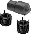
Drive the keys into the surrounding material for a more secure hold than thread-locking inserts. These inserts are used to repair or convert threads in soft metals such as aluminum. They’re comparable to Keensert® inserts.
18-8 stainless steel inserts are more corrosion resistant than black-phosphate steel. They may be mildly magnetic.
Black-phosphate steel inserts are mildly corrosion resistant.
Choose inserts with a thick wall for greater strength than thin-wall inserts, or to fill a large hole.
![]() For technical drawings and 3-D models, click on a part number.
For technical drawings and 3-D models, click on a part number.
Stainless Steel Helical Inserts
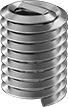
Also known as Heli-Coil inserts, these inserts have coils that expand once installed to securely anchor the insert. All have a prong for ease of installation. An installation tool grips the prong and reduces the coil diameter, enabling the insert to fit in tapped holes. Remove the prong to insert the screw. Installation requires a drill bit, a helical insert tap, an installation tool, and a prong break-off tool.
![]() For technical drawings and 3-D models, click on a part number.
For technical drawings and 3-D models, click on a part number.
Inserts | Through-Hole Taps | Closed-End Hole Taps | Installation Tools | ||||||||||
|---|---|---|---|---|---|---|---|---|---|---|---|---|---|
| Thread Size | Installed Lg. | Drill Bit Size | For Max. Hole Dia. | Specifications Met | Pkg. Qty. | Pkg. | Each | Each | Each | ||||
18-8 Stainless Steel—Right-Hand Threaded | |||||||||||||
| 5/8"-18 | 5/8" | 41/64" | 41/64" | MS124-662 | 1 | 000000000 | 00000 | 000000000 | 000000 | 000000000 | 000000 | 000000000 | 0000000 |
| 5/8"-18 | 0.938" | 41/64" | 41/64" | MS124-702 | 1 | 000000000 | 0000 | 000000000 | 00000 | 000000000 | 00000 | 000000000 | 000000 |
18-8 Stainless Steel—Left-Hand Threaded | |||||||||||||
| 5/8"-18 | 0.938" | 41/64" | 41/64" | __ | 1 | 000000000 | 0000 | 000000000 | 000000 | 000000 | 00 | 000000000 | 00000 |
Stainless Steel Screw-Locking Helical Inserts
A distorted thread grips the screw to resist loosening. Also known as Heli-Coil inserts, these inserts have coils that expand once installed to securely anchor the insert. All have a prong for ease of installation. An installation tool grips the prong and reduces the coil diameter, enabling the insert to fit in tapped holes. Remove the prong to insert the screw. Installation requires a drill bit, a helical insert tap, an installation tool, and a prong break-off tool.
![]() For technical drawings and 3-D models, click on a part number.
For technical drawings and 3-D models, click on a part number.
Inserts | Through-Hole Taps | Closed-End Hole Taps | Installation Tools | ||||||||||
|---|---|---|---|---|---|---|---|---|---|---|---|---|---|
| Thread Size | Installed Lg. | Drill Bit Size | For Max. Hole Dia. | Specifications Met | Pkg. Qty. | Pkg. | Each | Each | Each | ||||
18-8 Stainless Steel | |||||||||||||
| 5/8"-18 | 5/8" | 41/64" | 41/64" | MS21209F1010, NASM21209 | 1 | 000000000 | 00000 | 000000000 | 000000 | 000000000 | 000000 | 000000000 | 0000000 |
| 5/8"-18 | 0.938" | 41/64" | 41/64" | MS21209F1015, NASM21209 | 1 | 000000000 | 0000 | 000000000 | 00000 | 000000000 | 00000 | 000000000 | 000000 |
Helical Inserts with Installation Tools

Inserts come with a through-hole tap and installation tool. Also known as Heli-Coil inserts, they have coils that expand once installed to securely anchor the insert. All have a prong for ease of installation. An installation tool grips the prong and reduces the coil diameter, enabling the insert to fit in tapped holes. Remove the prong to insert the screw.
| Thread Size | Installed Lg. | Drill Bit Size | For Max. Hole Dia. | No. of Inserts Included | Includes | Each | |
18-8 Stainless Steel—Right-Hand Threaded | |||||||
|---|---|---|---|---|---|---|---|
| 5/8"-18 | 5/8" | 21/32" | 21/32" | 6 | Drill Bit, Through-Hole Tap, Installation Tool | 000000000 | 0000000 |
| 5/8"-18 | 0.938" | 41/64" | 41/64" | 6 | Drill Bit, Through-Hole Tap, Installation Tool | 000000000 | 000000 |
18-8 Stainless Steel—Left-Hand Threaded | |||||||
| 5/8"-18 | 0.938" | 41/64" | 41/64" | 2 | Through-Hole Tap, Installation Tool | 000000000 | 000000 |
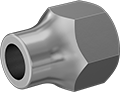
Alloy Steel Socket Nuts

Also known as Allen nuts, use these with socket head cap screws in recessed holes and tight spaces that don't have enough clearance for a wrench. Tighten them with a 6-point hex key. They can also be used as an insert by pressing or drawing them into nonhardened steel, cast iron, or soft nonferrous metal or by molding them into plastic, ceramic, fiber, and similar materials. Made from alloy steel, they're comparable in strength to Grade 9 bolts.
![]() For technical drawings and 3-D models, click on a part number.
For technical drawings and 3-D models, click on a part number.
| Thread Size | OD | Ht. | Threading | Thread Dp. | For Hole Dia. | Hex Key Size | Each | |
Alloy Steel | ||||||||
|---|---|---|---|---|---|---|---|---|
| 5/8"-18 | 0.98" | 1" | Partially Threaded | 0.5" | 1.028" | 5/8" | 000000000 | 00000 |