Filter by
Length
DFARS Specialty Metals
Export Control Classification Number (ECCN)
Specifications Met
For Rotary Motion
Nose Material
Body Material
Handle Material
Locking Type
Performance
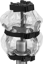
Coupling and Bearing Guards
 |
Shield couplings and bearings from dirt and debris while protecting fingers and tools from moving parts. Guards are electrically nonconductive, and resist chemicals, corrosion, and impact. They are OSHA compliant 29 CFR 1910.219 for rotating machinery. Guards come unassembled.
Mounting Hardware | |||||||||||||||||||||||||||||||||||||||||||||||||||||||||||||||||||||||||||||||||||||||||||||||||||
|---|---|---|---|---|---|---|---|---|---|---|---|---|---|---|---|---|---|---|---|---|---|---|---|---|---|---|---|---|---|---|---|---|---|---|---|---|---|---|---|---|---|---|---|---|---|---|---|---|---|---|---|---|---|---|---|---|---|---|---|---|---|---|---|---|---|---|---|---|---|---|---|---|---|---|---|---|---|---|---|---|---|---|---|---|---|---|---|---|---|---|---|---|---|---|---|---|---|---|---|
Lg. | Wd. | Ht. | Color | Material | Included | Specs. Met | Each | ||||||||||||||||||||||||||||||||||||||||||||||||||||||||||||||||||||||||||||||||||||||||||||
Polyethylene | |||||||||||||||||||||||||||||||||||||||||||||||||||||||||||||||||||||||||||||||||||||||||||||||||||
| 4" | 4" | 6" | Orange | 304 Stainless Steel | Yes | OSHA Compliant 29 CFR 1910.219, ANSI B11.19 | 6593K31 | 0000000 | |||||||||||||||||||||||||||||||||||||||||||||||||||||||||||||||||||||||||||||||||||||||||||
| 6" | 6" | 8" | Orange | 304 Stainless Steel | Yes | OSHA Compliant 29 CFR 1910.219, ANSI B11.19 | 6593K22 | 000000 | |||||||||||||||||||||||||||||||||||||||||||||||||||||||||||||||||||||||||||||||||||||||||||
| 8" | 8" | 12" | Orange | 304 Stainless Steel | Yes | OSHA Compliant 29 CFR 1910.219, ANSI B11.19 | 6593K24 | 000000 | |||||||||||||||||||||||||||||||||||||||||||||||||||||||||||||||||||||||||||||||||||||||||||
| 12" | 12" | 16" | Orange | 304 Stainless Steel | Yes | OSHA Compliant 29 CFR 1910.219, ANSI B11.19 | 6593K26 | 000000 | |||||||||||||||||||||||||||||||||||||||||||||||||||||||||||||||||||||||||||||||||||||||||||
| 16" | 16" | 20" | Orange | 304 Stainless Steel | Yes | OSHA Compliant 29 CFR 1910.219, ANSI B11.19 | 6593K28 | 000000 | |||||||||||||||||||||||||||||||||||||||||||||||||||||||||||||||||||||||||||||||||||||||||||
| 20" | 20" | 24" | Orange | 304 Stainless Steel | Yes | OSHA Compliant 29 CFR 1910.219, ANSI B11.19 | 6593K29 | 000000 | |||||||||||||||||||||||||||||||||||||||||||||||||||||||||||||||||||||||||||||||||||||||||||
Shaft Coupling Covers
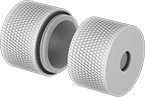 |
Extend the life of your rigid shaft couplings by blocking out dirt, water, lubricants, and other contaminants. These two-piece covers twist together to form a shell around the coupling. Viton® fluoroelastomer O-rings on the threads and around each shaft complete the seal. The outer surface is knurled for a good grip when tightening by hand. Covers are only for use with round, unkeyed shafts.
For Shaft Dia. | Overall Lg. | OD | For Rotary Motion | Each | |||||||||||||||||||||||||||||||||||||||||||||||||||||||||||||||||||||||||||||||||||||||||||||||
|---|---|---|---|---|---|---|---|---|---|---|---|---|---|---|---|---|---|---|---|---|---|---|---|---|---|---|---|---|---|---|---|---|---|---|---|---|---|---|---|---|---|---|---|---|---|---|---|---|---|---|---|---|---|---|---|---|---|---|---|---|---|---|---|---|---|---|---|---|---|---|---|---|---|---|---|---|---|---|---|---|---|---|---|---|---|---|---|---|---|---|---|---|---|---|---|---|---|---|---|
Acetal | |||||||||||||||||||||||||||||||||||||||||||||||||||||||||||||||||||||||||||||||||||||||||||||||||||
For Round Shafts | |||||||||||||||||||||||||||||||||||||||||||||||||||||||||||||||||||||||||||||||||||||||||||||||||||
| 1/2" × 1/2" | 2 3/16" | 1 3/4" | Continuous, Forward/Reverse, Start/Stop | 3403N11 | 000000 | ||||||||||||||||||||||||||||||||||||||||||||||||||||||||||||||||||||||||||||||||||||||||||||||
| 5/8" × 1/2" | 2 9/16" | 2" | Continuous, Forward/Reverse, Start/Stop | 3403N12 | 00000 | ||||||||||||||||||||||||||||||||||||||||||||||||||||||||||||||||||||||||||||||||||||||||||||||
| 5/8" × 5/8" | 2 9/16" | 2" | Continuous, Forward/Reverse, Start/Stop | 3403N13 | 00000 | ||||||||||||||||||||||||||||||||||||||||||||||||||||||||||||||||||||||||||||||||||||||||||||||
| 3/4" × 5/8" | 2 15/16" | 2 1/4" | Continuous, Forward/Reverse, Start/Stop | 3403N14 | 00000 | ||||||||||||||||||||||||||||||||||||||||||||||||||||||||||||||||||||||||||||||||||||||||||||||
| 1" × 3/4" | 3 5/16" | 2 1/2" | Continuous, Forward/Reverse, Start/Stop | 3403N16 | 00000 | ||||||||||||||||||||||||||||||||||||||||||||||||||||||||||||||||||||||||||||||||||||||||||||||
| 1" × 1" | 3 5/16" | 2 1/2" | Continuous, Forward/Reverse, Start/Stop | 3403N17 | 00000 | ||||||||||||||||||||||||||||||||||||||||||||||||||||||||||||||||||||||||||||||||||||||||||||||
| 1 1/8" × 1" | 3 9/16" | 2 5/8" | Continuous, Forward/Reverse, Start/Stop | 3403N18 | 00000 | ||||||||||||||||||||||||||||||||||||||||||||||||||||||||||||||||||||||||||||||||||||||||||||||
| 1 1/8" × 1 1/8" | 3 9/16" | 2 5/8" | Continuous, Forward/Reverse, Start/Stop | 3403N19 | 00000 | ||||||||||||||||||||||||||||||||||||||||||||||||||||||||||||||||||||||||||||||||||||||||||||||
| 1 1/4" × 1" | 3 11/16" | 2 3/4" | Continuous, Forward/Reverse, Start/Stop | 3403N21 | 00000 | ||||||||||||||||||||||||||||||||||||||||||||||||||||||||||||||||||||||||||||||||||||||||||||||
| 1 1/4" × 1 1/4" | 3 11/16" | 2 3/4" | Continuous, Forward/Reverse, Start/Stop | 3403N22 | 00000 | ||||||||||||||||||||||||||||||||||||||||||||||||||||||||||||||||||||||||||||||||||||||||||||||
| 1 1/2" × 1" | 4 1/16" | 3" | Continuous, Forward/Reverse, Start/Stop | 3403N23 | 000000 | ||||||||||||||||||||||||||||||||||||||||||||||||||||||||||||||||||||||||||||||||||||||||||||||
| 1 1/2" × 1 1/2" | 4 1/16" | 3" | Continuous, Forward/Reverse, Start/Stop | 3403N24 | 000000 | ||||||||||||||||||||||||||||||||||||||||||||||||||||||||||||||||||||||||||||||||||||||||||||||
| 2" × 2" | 5 3/16" | 3 3/4" | Continuous, Forward/Reverse, Start/Stop | 3403N25 | 000000 | ||||||||||||||||||||||||||||||||||||||||||||||||||||||||||||||||||||||||||||||||||||||||||||||
L-Handle Retractable Spring Plungers
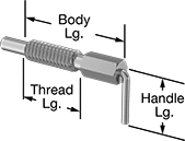 |
The L-handle on these spring plungers takes up less space than a T-handle and swivels to avoid obstacles. Pull it back to manually retract the nose and position, align, and lock components as needed for your job.
Spring plungers are available with or without a threadlocker. Those with a threadlocker won't wiggle loose from vibration. Spring plungers without a threadlocker are easier to remove.
Steel Nose—The strongest, most wear-resistant noses, these won't deform from stress and vibration. Steel is best for dry environments, however, since moisture will cause it to rust.
18-8 Stainless Steel Nose—The choice for wet and outdoor environments, 18-8 stainless steel resists rusting. It's strong enough for most jobs, but won't withstand stress and vibration as well as steel.
Twist-to-Lock—Free up both hands to adjust your workpiece or switch out parts without the plunger springing back and getting in the way. Pull back the handle and twist to lock the nose in its retracted position.
Nose | Nose Force, lbf | Body | Handle | Twist-to-Lock | |||||||||||||||||||||||||||||||||||||||||||||||||||||||||||||||||||||||||||||||||||||||||||||||
|---|---|---|---|---|---|---|---|---|---|---|---|---|---|---|---|---|---|---|---|---|---|---|---|---|---|---|---|---|---|---|---|---|---|---|---|---|---|---|---|---|---|---|---|---|---|---|---|---|---|---|---|---|---|---|---|---|---|---|---|---|---|---|---|---|---|---|---|---|---|---|---|---|---|---|---|---|---|---|---|---|---|---|---|---|---|---|---|---|---|---|---|---|---|---|---|---|---|---|---|
Thread Size | Thread Lg. | Extended Lg. | Dia. | Extended | Compressed | Material | Lg. | Material | Lg. | Drive Style | Each | ||||||||||||||||||||||||||||||||||||||||||||||||||||||||||||||||||||||||||||||||||||||||
Steel Nose | |||||||||||||||||||||||||||||||||||||||||||||||||||||||||||||||||||||||||||||||||||||||||||||||||||
| 10-32 | 0.53" | 0.188" | 0.125" | 0.1 | 0.5 | Zinc-Plated Steel | 0.9" | Steel | 3/4" | External Hex | 3403A95 | 000000 | |||||||||||||||||||||||||||||||||||||||||||||||||||||||||||||||||||||||||||||||||||||||
18-8 Stainless Steel Nose | |||||||||||||||||||||||||||||||||||||||||||||||||||||||||||||||||||||||||||||||||||||||||||||||||||
| 10-32 | 0.53" | 0.188" | 0.125" | 0.1 | 0.5 | 18-8 Stainless Steel | 0.9" | 18-8 Stainless Steel | 3/4" | External Hex | 3403A96 | 00000 | |||||||||||||||||||||||||||||||||||||||||||||||||||||||||||||||||||||||||||||||||||||||
Puller Protection Blankets