


Filter by
Shaft Diameter


Maximum Torque
DFARS Specialty Metals
Export Control Classification Number (ECCN)
Torque Limiter Type
High-Torque Flexible Shaft Couplings
 |  |
(Each Component Sold Separately) |
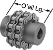
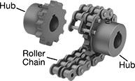
With a rugged roller-chain design, these couplings provide excellent torque and angular misalignment capacities. Lubrication is required. Fasten to your shaft by tightening the set screws, which bite into the shaft to hold it.
A complete coupling consists of two hubs and one roller chain (each component sold separately). Complete couplings meet ANSI B29.23M-1995.
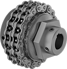
Optional covers retain grease lubrication and provide protection from abrasion and corrosion.
Hubs | Steel Roller Chain | Orange Nylon Covers | |||||||||||||||||
|---|---|---|---|---|---|---|---|---|---|---|---|---|---|---|---|---|---|---|---|
Misalignment Capability | Roller Chain | ||||||||||||||||||
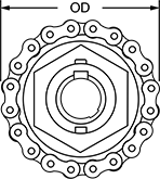
Overall Lg. | OD | OD with Cover | For Shaft Type | For Rotary Motion | Choose a Shaft Diameter | Each | Max. Rotation Speed, rpm | Max. Torque, in·lbf | Parallel | Angular | No. | Standard | Each | Each | |||||
Steel Hubs | |||||||||||||||||||
| 2 9/16" | 2 13/32" | 4" | Keyed | Continuous | 1/2", 5/8", 3/4" | 6407K41 | 000000 | 5,000 | 1,355 | 0.012" | 2° | 40-2 | ANSI | 6407K51 | 000000 | 6407K71 | 0000000 | ||
| 2 9/16" | 3 3/64" | 4" | Keyed | Continuous | 5/8", 3/4", 7/8", 15/16", 1", 1 1/8", 1 1/4" | 6407K42 | 00000 | 5,000 | 2,410 | 0.012" | 2° | 40-2 | ANSI | 6407K52 | 00000 | 6407K72 | 000000 | ||
| 2 29/32" | 3 25/32" | 5 1/8" | Keyed | Continuous | 3/4", 7/8", 1", 1 1/8", 1 1/4", 1 3/8", 1 7/16", 1 1/2", 1 5/8" | 6407K43 | 00000 | 4,000 | 4,610 | 0.012" | 2° | 50-2 | ANSI | 6407K53 | 00000 | 6407K73 | 000000 | ||
| 3 29/64" | 5" | 6 3/8" | Keyed | Continuous | 1", 1 1/8", 1 1/4", 1 3/8", 1 7/16", 1 1/2", 1 5/8", 1 3/4", 1 7/8", 1 15/16", 2", 2 1/8", 2 1/4", 2 3/8", 2 7/16" | 6407K44 | 00000 | 3,000 | 10,900 | 0.012" | 1.5° | 60-2 | ANSI | 6407K54 | 00000 | 6407K74 | 000000 | ||
High-Torque Friction Torque Limiters
Shaft-to-Shaft
 |  |
Single Spring—Single-spring torque limiters let you make finer torque adjustments than double-spring torque limiters but can only withstand half as much torque.
Double Spring—Double-spring torque limiters handle twice as much torque as single-spring torque limiters but are not the best for making precise adjustments at low torques.
Misalignment Capability | Roller Chain | |||||||||||||||
|---|---|---|---|---|---|---|---|---|---|---|---|---|---|---|---|---|
For Shaft Dia. | For Shaft Type | Torque, ft·lbf | Max. Rotation Speed, rpm | Parallel | Angular | OD | Overall Lg. | Keyway Wd. × Keyway Dp. | Drive Direction | Shaft Mount Type | Standard | Trade No. | Each | |||
Single Spring | ||||||||||||||||
| 1/2" × 1/2" | Round × Round | 0 to 25 | 1,800 | 0.01" | 3° | 2 3/4" | 2 1/4" | — | Clockwise and Counterclockwise | Set Screw | ANSI | 35-2 | 4782N111 | 0000000 | ||
| 1/2" × 5/8" | Round × Keyed | 0 to 25 | 1,800 | 0.01" | 3° | 2 3/4" | 2 1/4" | 3/16" × 3/32" | Clockwise and Counterclockwise | Set Screw | ANSI | 35-2 | 4782N113 | 000000 | ||
| 1/2" × 3/4" | Round × Keyed | 0 to 25 | 1,800 | 0.01" | 3° | 2 3/4" | 2 1/4" | 3/16" × 3/32" | Clockwise and Counterclockwise | Set Screw | ANSI | 35-2 | 4782N115 | 000000 | ||
| 5/8" × 5/8" | Keyed × Keyed | 0 to 25 | 1,800 | 0.01" | 3° | 2 3/4" | 2 1/4" | 3/16" × 3/32" 3/16" × 3/32" | Clockwise and Counterclockwise | Set Screw | ANSI | 35-2 | 4782N117 | 000000 | ||
| 5/8" × 3/4" | Keyed × Keyed | 0 to 25 | 1,800 | 0.01" | 3° | 2 3/4" | 2 1/4" | 3/16" × 3/32" 3/16" × 3/32" | Clockwise and Counterclockwise | Set Screw | ANSI | 35-2 | 4782N119 | 000000 | ||
| 3/4" × 3/4" | Keyed × Keyed | 0 to 25 | 1,800 | 0.01" | 3° | 2 3/4" | 2 1/4" | 3/16" × 3/32" 3/16" × 3/32" | Clockwise and Counterclockwise | Set Screw | ANSI | 35-2 | 4782N122 | 000000 | ||
| 1" × 1" | Keyed × Keyed | 0 to 75 | 1,800 | 0.01" | 3° | 3 11/16" | 2 13/16" | 1/4" × 1/8" 1/4" × 1/8" | Clockwise and Counterclockwise | Set Screw | ANSI | 40-2 | 4782N131 | 000000 | ||
| 12 mm × 12 mm | Keyed × Keyed | 0 to 25 | 1,800 | 0.01" | 3° | 2 3/4" | 2 1/4" | 4 mm × 2 mm 4 mm × 2 mm | Clockwise and Counterclockwise | Set Screw | ANSI | 35-2 | 4782N124 | 000000 | ||
| 12 mm × 15 mm | Keyed × Keyed | 0 to 25 | 1,800 | 0.01" | 3° | 2 3/4" | 2 1/4" | 4 mm × 2 mm 5 mm × 2.5 mm | Clockwise and Counterclockwise | Set Screw | ANSI | 35-2 | 4782N126 | 000000 | ||
| 15 mm × 15 mm | Keyed × Keyed | 0 to 25 | 1,800 | 0.01" | 3° | 2 3/4" | 2 1/4" | 5 mm × 2.5 mm 5 mm × 2.5 mm | Clockwise and Counterclockwise | Set Screw | ANSI | 35-2 | 4782N128 | 000000 | ||
| 15 mm × 20 mm | Keyed × Keyed | 0 to 75 | 1,800 | 0.01" | 3° | 3 11/16" | 2 13/16" | 5 mm × 2.5 mm 6 mm × 3 mm | Clockwise and Counterclockwise | Set Screw | ANSI | 40-2 | 4782N133 | 000000 | ||
| 20 mm × 20 mm | Keyed × Keyed | 0 to 75 | 1,800 | 0.01" | 3° | 3 11/16" | 2 13/16" | 6 mm × 3 mm 6 mm × 3 mm | Clockwise and Counterclockwise | Set Screw | ANSI | 40-2 | 4782N135 | 000000 | ||
| 20 mm × 25 mm | Keyed × Keyed | 0 to 75 | 1,800 | 0.01" | 3° | 3 11/16" | 2 13/16" | 6 mm × 3 mm 8 mm × 4 mm | Clockwise and Counterclockwise | Set Screw | ANSI | 40-2 | 4782N137 | 000000 | ||
| 25 mm × 25 mm | Keyed × Keyed | 0 to 75 | 1,800 | 0.01" | 3° | 3 11/16" | 2 13/16" | 8 mm × 4 mm 8 mm × 4 mm | Clockwise and Counterclockwise | Set Screw | ANSI | 40-2 | 4782N139 | 000000 | ||
Double Spring | ||||||||||||||||
| 1/2" × 1/2" | Round × Round | 0 to 50 | 1,800 | 0.01" | 3° | 2 3/4" | 2 1/4" | — | Clockwise and Counterclockwise | Set Screw | ANSI | 35-2 | 4782N112 | 000000 | ||
| 1/2" × 5/8" | Round × Keyed | 0 to 50 | 1,800 | 0.01" | 3° | 2 3/4" | 2 1/4" | 3/16" × 3/32" | Clockwise and Counterclockwise | Set Screw | ANSI | 35-2 | 4782N114 | 000000 | ||
| 1/2" × 3/4" | Round × Keyed | 0 to 50 | 1,800 | 0.01" | 3° | 2 3/4" | 2 1/4" | 3/16" × 3/32" | Clockwise and Counterclockwise | Set Screw | ANSI | 35-2 | 4782N116 | 000000 | ||
| 5/8" × 5/8" | Keyed × Keyed | 0 to 50 | 1,800 | 0.01" | 3° | 2 3/4" | 2 1/4" | 3/16" × 3/32" 3/16" × 3/32" | Clockwise and Counterclockwise | Set Screw | ANSI | 35-2 | 4782N118 | 000000 | ||
| 5/8" × 3/4" | Keyed × Keyed | 0 to 50 | 1,800 | 0.01" | 3° | 2 3/4" | 2 1/4" | 3/16" × 3/32" 3/16" × 3/32" | Clockwise and Counterclockwise | Set Screw | ANSI | 35-2 | 4782N121 | 000000 | ||
| 3/4" × 3/4" | Keyed × Keyed | 0 to 50 | 1,800 | 0.01" | 3° | 2 3/4" | 2 1/4" | 3/16" × 3/32" 3/16" × 3/32" | Clockwise and Counterclockwise | Set Screw | ANSI | 35-2 | 4782N123 | 000000 | ||
| 1" × 1" | Keyed × Keyed | 0 to 150 | 1,800 | 0.01" | 3° | 3 11/16" | 2 13/16" | 1/4" × 1/8" 1/4" × 1/8" | Clockwise and Counterclockwise | Set Screw | ANSI | 40-2 | 4782N132 | 000000 | ||
| 12 mm × 12 mm | Keyed × Keyed | 0 to 50 | 1,800 | 0.01" | 3° | 2 3/4" | 2 1/4" | 4 mm × 2 mm 4 mm × 2 mm | Clockwise and Counterclockwise | Set Screw | ANSI | 35-2 | 4782N125 | 000000 | ||
| 12 mm × 15 mm | Keyed × Keyed | 0 to 50 | 1,800 | 0.01" | 3° | 2 3/4" | 2 1/4" | 4 mm × 2 mm 5 mm × 2.5 mm | Clockwise and Counterclockwise | Set Screw | ANSI | 35-2 | 4782N127 | 000000 | ||
| 15 mm × 15 mm | Keyed × Keyed | 0 to 50 | 1,800 | 0.01" | 3° | 2 3/4" | 2 1/4" | 5 mm × 2.5 mm 5 mm × 2.5 mm | Clockwise and Counterclockwise | Set Screw | ANSI | 35-2 | 4782N129 | 000000 | ||
| 15 mm × 20 mm | Keyed × Keyed | 0 to 150 | 1,800 | 0.01" | 3° | 3 11/16" | 2 13/16" | 5 mm × 2.5 mm 6 mm × 3 mm | Clockwise and Counterclockwise | Set Screw | ANSI | 40-2 | 4782N134 | 000000 | ||
| 20 mm × 20 mm | Keyed × Keyed | 0 to 150 | 1,800 | 0.01" | 3° | 3 11/16" | 2 13/16" | 6 mm × 3 mm 6 mm × 3 mm | Clockwise and Counterclockwise | Set Screw | ANSI | 40-2 | 4782N136 | 000000 | ||
| 20 mm × 25 mm | Keyed × Keyed | 0 to 150 | 1,800 | 0.01" | 3° | 3 11/16" | 2 13/16" | 6 mm × 3 mm 8 mm × 4 mm | Clockwise and Counterclockwise | Set Screw | ANSI | 40-2 | 4782N138 | 000000 | ||
| 25 mm × 25 mm | Keyed × Keyed | 0 to 150 | 1,800 | 0.01" | 3° | 3 11/16" | 2 13/16" | 8 mm × 4 mm 8 mm × 4 mm | Clockwise and Counterclockwise | Set Screw | ANSI | 40-2 | 4782N141 | 000000 | ||
