


For Shaft Diameter For Shaft Diameter |
|---|
OD OD |
|---|
ID ID |
|---|
|
|
|
Width Width |
|---|
|
|
|
Maximum Torque Maximum Torque |
|---|
Spring Material Spring Material |
|---|
|


Maximum Speed Maximum Speed |
|---|
|
For Housing ID For Housing ID |
|---|
Construction Construction |
|---|
|
|
Cage Material Cage Material |
|---|
|
DFARS (Defense Acquisition Regulations Supplement) DFARS (Defense AcquisitionRegulations Supplement) |
|---|
REACH (Registration, Evaluation, Authorization and Restriction of Chemicals) REACH (Registration,Evaluation, Authorization and Restriction of Chemicals) |
|---|
|
RoHS (Restriction of Hazardous Substances) RoHS (Restriction ofHazardous Substances) |
|---|
|
Dynamic Radial Load Capacity Dynamic Radial Load Capacity |
|---|
|
Lubrication Lubrication |
|---|
|
Torque Limiter Type Torque Limiter Type |
|---|
|
About Ball and Roller Bearings
More
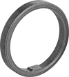
One-Way Locking Needle-Roller Bearing Clutches
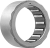
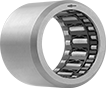
The needles in these bearings roll freely in one direction, but lock to transmit torque when the rotation of the shaft is reversed. Also known as drawn-cup roller clutches. An arrow on the lip indicates the rotational direction that locks the bearings.
Single-row bearings do not support loads from any direction. To support radial loads, use with our Needle-Roller Bearings.
Triple-row bearings support radial loads.
Bearings with 301 stainless steel springs handle higher temperatures than bearings with acetal springs.
![]() For technical drawings and 3-D models, click on a part number.
For technical drawings and 3-D models, click on a part number.
Radial Load Cap., lbs. | ||||||||||||
|---|---|---|---|---|---|---|---|---|---|---|---|---|
| For Shaft Dia. | For Housing ID | Wd. | Ring Material | Dynamic | Static | Max. Speed, rpm | Max. Torque, ft.-lbs. | Lubrication | For Shaft Surface Smoothness (Ra), microinch | Temp. Range, °F | Each | |
Single Row | ||||||||||||
Acetal Plastic Springs | ||||||||||||
| 1/8" | 9/32" | 1/4" | Steel | __ | __ | 34,000 | 0.2 | Required | 16 | -20° to 200° | 0000000 | 000000 |
| 1/4" | 7/16" | 1/2" | Steel | __ | __ | 20,000 | 1.5 | Required | 16 | -20° to 200° | 0000000 | 00000 |
| 3/8" | 5/8" | 1/2" | Steel | __ | __ | 18,000 | 4 | Required | 16 | -20° to 200° | 0000000 | 00000 |
| 1/2" | 3/4" | 1/2" | Steel | __ | __ | 17,000 | 6.5 | Required | 16 | -20° to 200° | 0000000 | 00000 |
| 5/8" | 7/8" | 5/8" | Steel | __ | __ | 14,000 | 12 | Required | 16 | -20° to 200° | 000000 | 00000 |
| 3/4" | 1" | 5/8" | Steel | __ | __ | 12,000 | 17 | Required | 16 | -20° to 200° | 000000 | 00000 |
| 1" | 1 5/16" | 5/8" | Steel | __ | __ | 8,700 | 35 | Required | 16 | -20° to 200° | 000000 | 00000 |
301 Stainless Steel Springs | ||||||||||||
| 1/4" | 7/16" | 1/2" | Steel | __ | __ | 20,000 | 1.5 | Required | 16 | -20° to 250° | 0000000 | 00000 |
| 3/8" | 5/8" | 1/2" | Steel | __ | __ | 18,000 | 4 | Required | 16 | -20° to 250° | 0000000 | 00000 |
| 1/2" | 3/4" | 1/2" | Steel | __ | __ | 17,000 | 6.5 | Required | 16 | -20° to 250° | 0000000 | 00000 |
| 5/8" | 7/8" | 5/8" | Steel | __ | __ | 14,000 | 12 | Required | 16 | -20° to 250° | 0000000 | 00000 |
| 3/4" | 1" | 5/8" | Steel | __ | __ | 12,000 | 17 | Required | 16 | -20° to 250° | 0000000 | 00000 |
| 1" | 1 5/16" | 5/8" | Steel | __ | __ | 8,700 | 35 | Required | 16 | -20° to 250° | 0000000 | 00000 |
Steel Springs | ||||||||||||
| 6mm | 10mm | 12mm | Steel | __ | __ | 23,000 | 1.3 | Required | 16 | 10° to 150° | 0000000 | 00000 |
| 8mm | 12mm | 12mm | Steel | __ | __ | 17,000 | 2.3 | Required | 16 | 10° to 150° | 0000000 | 00000 |
| 10mm | 14mm | 12mm | Steel | __ | __ | 14,000 | 3.9 | Required | 16 | 10° to 150° | 0000000 | 00000 |
| 12mm | 18mm | 16mm | Steel | __ | __ | 11,000 | 9 | Required | 16 | 10° to 150° | 0000000 | 00000 |
| 14mm | 20mm | 16mm | Steel | __ | __ | 9,500 | 12 | Required | 16 | 10° to 150° | 0000000 | 00000 |
| 16mm | 22mm | 16mm | Steel | __ | __ | 8,500 | 15 | Required | 16 | 10° to 150° | 0000000 | 00000 |
| 18mm | 24mm | 16mm | Steel | __ | __ | 7,500 | 17 | Required | 16 | 10° to 150° | 0000000 | 00000 |
| 20mm | 26mm | 16mm | Steel | __ | __ | 7,000 | 21 | Required | 16 | 10° to 150° | 0000000 | 00000 |
| 25mm | 32mm | 20mm | Steel | __ | __ | 5,500 | 45 | Required | 16 | 10° to 150° | 0000000 | 00000 |
| 30mm | 37mm | 20mm | Steel | __ | __ | 4,500 | 65 | Required | 16 | 10° to 150° | 0000000 | 00000 |
| 35mm | 42mm | 20mm | Steel | __ | __ | 3,900 | 85 | Required | 16 | 10° to 150° | 0000000 | 00000 |
Triple Row | ||||||||||||
301 Stainless Steel Springs | ||||||||||||
| 3/8" | 5/8" | 7/8" | Steel | 1,350 | 1,100 | 18,000 | 4 | Required | 16 | -20° to 250° | 0000000 | 00000 |
| 1/2" | 3/4" | 7/8" | Steel | 1,600 | 1,450 | 17,000 | 6.5 | Required | 16 | -20° to 250° | 0000000 | 00000 |
| 5/8" | 7/8" | 1" | Steel | 1,800 | 1,800 | 14,000 | 12 | Required | 16 | -20° to 250° | 0000000 | 00000 |
| 3/4" | 1" | 1" | Steel | 2,000 | 2,200 | 12,000 | 17 | Required | 16 | -20° to 250° | 0000000 | 00000 |
| 1" | 1 5/16" | 1.063" | Steel | 3,450 | 3,950 | 8,700 | 35 | Required | 16 | -20° to 250° | 0000000 | 00000 |
| 8mm | 14mm | 20mm | Steel | 940 | 680 | 21,000 | 3.2 | Required | 16 | -20° to 250° | 0000000 | 00000 |
| 10mm | 16mm | 20mm | Steel | 1,050 | 850 | 19,000 | 4.2 | Required | 16 | -20° to 250° | 0000000 | 00000 |
| 12mm | 18mm | 26mm | Steel | 1,400 | 1,300 | 19,000 | 10 | Required | 16 | -20° to 250° | 0000000 | 00000 |
| 16mm | 22mm | 26mm | Steel | 1,450 | 1,600 | 14,000 | 16 | Required | 16 | -20° to 250° | 0000000 | 00000 |
| 20mm | 26mm | 26mm | Steel | 1,800 | 2,100 | 11,000 | 24 | Required | 16 | -20° to 250° | 0000000 | 00000 |
| 25mm | 32mm | 30mm | Steel | 2,500 | 2,900 | 8,700 | 50 | Required | 16 | -20° to 250° | 0000000 | 00000 |
| 30mm | 37mm | 30mm | Steel | 2,550 | 3,350 | 7,300 | 70 | Required | 16 | -20° to 250° | 0000000 | 00000 |
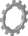
One-Way Locking Ball Bearing Clutches

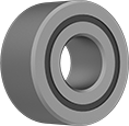
Internal locking elements (sprags) lock to transmit torque in one direction while turning freely in the other direction. Use them in applications where precision movement is required, such as pick-and-place and automated indexing conveyor systems. Shields keep out dust and contaminants.
Shielded bearings dissipate heat better than sealed bearings, but don’t keep out as much dust.
For dirty or dusty environments, sealed bearings are the best choice, since they block out contaminants better than shielded bearings.
![]() For technical drawings and 3-D models, click on a part number.
For technical drawings and 3-D models, click on a part number.
Radial Load Cap., lbs. | |||||||||||||
|---|---|---|---|---|---|---|---|---|---|---|---|---|---|
| Bearing Trade Number | For Shaft Dia., mm | For Housing ID, mm | Wd., mm | Ring Material | Dynamic | Static | Max. Speed, rpm | Max. Torque, ft.-lbs. | Lubrication | Temp. Range, °F | ABEC Rating | Each | |
Shielded | |||||||||||||
| 608-2Z | 8 | 22 | 9 | Steel | 720 | 190 | 15,000 | 1.5 | Lubricated | -40° to 170° | ABEC-1 | 0000000 | 0000000 |
| FZ 6201 | 12 | 32 | 10 | Steel | 1,150 | 530 | 10,000 | 6.5 | Lubricated | -40° to 170° | ABEC-1 | 0000000 | 000000 |
| FZ 6202 | 15 | 35 | 11 | Steel | 1,160 | 540 | 9,400 | 15 | Lubricated | -40° to 170° | ABEC-1 | 0000000 | 000000 |
| FZ 6203 | 17 | 40 | 12 | Steel | 1,270 | 640 | 8,200 | 23 | Lubricated | -40° to 170° | ABEC-1 | 0000000 | 000000 |
| FZ 6204 | 20 | 47 | 14 | Steel | 1,540 | 940 | 6,800 | 64 | Lubricated | -40° to 170° | ABEC-1 | 0000000 | 000000 |
| FZ 6205 | 25 | 52 | 15 | Steel | 1,620 | 1,040 | 5,600 | 70 | Lubricated | -40° to 170° | ABEC-1 | 0000000 | 000000 |
| FZ 6206 | 30 | 62 | 16 | Steel | 1,730 | 1,270 | 4,000 | 165 | Lubricated | -40° to 170° | ABEC-1 | 0000000 | 000000 |
| FZ 6207 | 35 | 72 | 17 | Steel | 1,830 | 1,490 | 3,600 | 240 | Lubricated | -40° to 170° | ABEC-1 | 0000000 | 000000 |
| FZ 6208 | 40 | 80 | 22 | Steel | 2,010 | 1,790 | 3,000 | 305 | Lubricated | -40° to 170° | ABEC-1 | 0000000 | 000000 |
Sealed | |||||||||||||
| FZ 6201 2RS | 12 | 32 | 14 | Steel | 1,150 | 530 | 10,000 | 6.5 | Lubricated | -40° to 170° | ABEC-1 | 0000000 | 000000 |
| FZ 6202 2RS | 15 | 35 | 16 | Steel | 1,160 | 540 | 8,400 | 15 | Lubricated | -40° to 170° | ABEC-1 | 0000000 | 000000 |
| FZ 6203 2RS | 17 | 40 | 17 | Steel | 1,270 | 640 | 7,300 | 23 | Lubricated | -40° to 170° | ABEC-1 | 0000000 | 000000 |
| FZ 6204 2RS | 20 | 47 | 19 | Steel | 1,540 | 940 | 6,000 | 64 | Lubricated | -40° to 170° | ABEC-1 | 0000000 | 000000 |
| FZ 6205 2RS | 25 | 52 | 20 | Steel | 1,620 | 1,040 | 5,200 | 70 | Lubricated | -40° to 170° | ABEC-1 | 0000000 | 000000 |
| FZ 6206 2RS | 30 | 62 | 21 | Steel | 1,730 | 1,270 | 4,200 | 165 | Lubricated | -40° to 170° | ABEC-1 | 0000000 | 000000 |
| FZ 6207 2RS | 35 | 72 | 22 | Steel | 1,830 | 1,490 | 3,600 | 240 | Lubricated | -40° to 170° | ABEC-1 | 0000000 | 000000 |
| FZ 6208 2RS | 40 | 80 | 27 | Steel | 2,010 | 1,790 | 3,000 | 305 | Lubricated | -40° to 170° | ABEC-1 | 0000000 | 000000 |
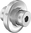
Torque-Limiting Shaft-to-Gear Couplings
Adjust your system's torque limit by hand. In the event of excess torque, these couplings slip to protect motors and drivetrains, and then resume driving once the load has been reduced. You can adjust the torque level without removing them from your shaft.
![]() For technical drawings and 3-D models, click on a part number.
For technical drawings and 3-D models, click on a part number.
Keyway | ||||||||||
|---|---|---|---|---|---|---|---|---|---|---|
| For Shaft Dia. | Max. Torque | Max. Speed, rpm | OD | Overall Lg. | Wd. | Dp. | Torque-Limiting Direction | Mounting Hole Thread Size | Each | |
For Round Shafts | ||||||||||
| 1/4" | 16 in.-lbs. @ 50 rpm | 50 | 1" | 1 1/2" | __ | __ | Clockwise and Counterclockwise | 4-40 | 0000000 | 0000000 |
| 3/8" | 16 in.-lbs. @ 50 rpm | 50 | 1" | 1 1/2" | __ | __ | Clockwise and Counterclockwise | 4-40 | 0000000 | 000000 |
| 3/8" | 25 in.-lbs. @ 50 rpm | 50 | 1 3/8" | 2 1/2" | __ | __ | Clockwise and Counterclockwise | 6-32 | 0000000 | 000000 |
| 1/2" | 25 in.-lbs. @ 50 rpm | 50 | 1 3/8" | 2 1/2" | __ | __ | Clockwise and Counterclockwise | 6-32 | 0000000 | 000000 |
| 1/2" | 50 in.-lbs. @ 50 rpm | 50 | 1 5/8" | 2 1/2" | __ | __ | Clockwise and Counterclockwise | 6-32 | 0000000 | 000000 |
| 1/2" | 75 in.-lbs. @ 50 rpm | 50 | 2 1/4" | 2 1/2" | __ | __ | Clockwise and Counterclockwise | 8-32 | 0000000 | 000000 |
| 5/8" | 50 in.-lbs. @ 50 rpm | 50 | 1 5/8" | 2 1/2" | __ | __ | Clockwise and Counterclockwise | 6-32 | 0000000 | 000000 |
| 5/8" | 75 in.-lbs. @ 50 rpm | 50 | 2 1/4" | 2 1/2" | __ | __ | Clockwise and Counterclockwise | 8-32 | 0000000 | 000000 |
For Keyed Shafts | ||||||||||
| 1/4" | 16 in.-lbs. @ 50 rpm | 50 | 1" | 1 1/2" | 1/16" | 1/32" | Clockwise and Counterclockwise | 4-40 | 0000000 | 000000 |
| 3/8" | 25 in.-lbs. @ 50 rpm | 50 | 1 3/8" | 2 1/2" | 3/32" | 3/64" | Clockwise and Counterclockwise | 6-32 | 0000000 | 000000 |
| 1/2" | 50 in.-lbs. @ 50 rpm | 50 | 1 5/8" | 2 1/2" | 1/8" | 1/16" | Clockwise and Counterclockwise | 6-32 | 0000000 | 000000 |
| 1/2" | 75 in.-lbs. @ 50 rpm | 50 | 2 1/4" | 2 1/2" | 1/8" | 1/16" | Clockwise and Counterclockwise | 8-32 | 0000000 | 000000 |
Air-Powered Torque-Limiting Shaft Couplings


Often used in automated systems, these couplings are air actuated so you can adjust the torque during operation. In the event of excess torque, they slip to protect motors and drivetrains, and then resume driving once the load has been reduced. You can adjust the torque level without removing them from your shaft.
![]() For technical drawings and 3-D models, click on a part number.
For technical drawings and 3-D models, click on a part number.
Keyway | Air Inlet | ||||||||||||
|---|---|---|---|---|---|---|---|---|---|---|---|---|---|
| For Shaft Dia. | Max. Torque | Max. Pressure, psi | Max. Speed | OD | Overall Lg. | Wd. | Dp. | Torque-Limiting Direction | Thread Size | Thread Type | Gender | Each | |
For Round Shafts | |||||||||||||
| 1/4" | 20 in.-lbs. @ 100 psi | 100 | Not Rated | 1 1/4" | 2 1/2" | __ | __ | Clockwise and Counterclockwise | 10-32 | UNF | Female | 0000000 | 0000000 |
| 3/8" | 50 in.-lbs. @ 100 psi | 100 | Not Rated | 1 1/2" | 3 3/8" | __ | __ | Clockwise and Counterclockwise | 10-32 | UNF | Female | 0000000 | 000000 |
| 1/2" | 100 in.-lbs. @ 100 psi | 100 | Not Rated | 2" | 3 5/8" | __ | __ | Clockwise and Counterclockwise | 10-32 | UNF | Female | 0000000 | 000000 |
| 5/8" | 300 in.-lbs. @ 100 psi | 100 | Not Rated | 2 3/4" | 3 5/8" | __ | __ | Clockwise and Counterclockwise | 10-32 | UNF | Female | 0000000 | 000000 |
For Keyed Shafts | |||||||||||||
| 1/4" | 20 in.-lbs. @ 100 psi | 100 | Not Rated | 1 1/4" | 2 1/2" | 1/16" | 1/32" | Clockwise and Counterclockwise | 10-32 | UNF | Female | 0000000 | 000000 |
| 3/8" | 50 in.-lbs. @ 100 psi | 100 | Not Rated | 1 1/2" | 3 3/8" | 3/32" | 3/64" | Clockwise and Counterclockwise | 10-32 | UNF | Female | 0000000 | 000000 |
| 1/2" | 100 in.-lbs. @ 100 psi | 100 | Not Rated | 2" | 3 5/8" | 1/8" | 1/16" | Clockwise and Counterclockwise | 10-32 | UNF | Female | 0000000 | 000000 |
| 5/8" | 300 in.-lbs. @ 100 psi | 100 | Not Rated | 2 3/4" | 3 5/8" | 3/16" | 3/32" | Clockwise and Counterclockwise | 10-32 | UNF | Female | 0000000 | 000000 |
Air-Powered Torque-Limiting Shaft-to-Gear Couplings
Often used in automated systems, these couplings are both air actuated and remotely adjustable, so you can adjust the torque setting even during operation. In the event of excess torque, they slip to protect motors and drivetrains, and then resume driving once the load has been reduced.
![]() For technical drawings and 3-D models, click on a part number.
For technical drawings and 3-D models, click on a part number.
Keyway | Air Inlet | |||||||||||||
|---|---|---|---|---|---|---|---|---|---|---|---|---|---|---|
| For Shaft Dia. | Max. Torque | Max. Pressure, psi | Max. Speed | OD | Overall Lg. | Wd. | Dp. | Torque-Limiting Direction | Thread Size | Thread Type | Gender | Mounting Hole Thread Size | Each | |
For Round Shafts | ||||||||||||||
| 1/4" | 20 in.-lbs. @ 100 psi | 100 | Not Rated | 1 1/4" | 2 1/2" | __ | __ | Clockwise and Counterclockwise | 10-32 | UNF | Female | 4-40 | 0000000 | 0000000 |
| 3/8" | 50 in.-lbs. @ 100 psi | 100 | Not Rated | 1 1/2" | 3 3/8" | __ | __ | Clockwise and Counterclockwise | 10-32 | UNF | Female | 6-32 | 0000000 | 000000 |
| 1/2" | 100 in.-lbs. @ 100 psi | 100 | Not Rated | 2" | 3 5/8" | __ | __ | Clockwise and Counterclockwise | 10-32 | UNF | Female | 6-32 | 0000000 | 000000 |
| 5/8" | 300 in.-lbs. @ 100 psi | 100 | Not Rated | 2 3/4" | 3 5/8" | __ | __ | Clockwise and Counterclockwise | 10-32 | UNF | Female | 8-32 | 0000000 | 000000 |
For Keyed Shafts | ||||||||||||||
| 1/4" | 20 in.-lbs. @ 100 psi | 100 | Not Rated | 1 1/4" | 2 1/2" | 1/16" | 1/32" | Clockwise and Counterclockwise | 10-32 | UNF | Female | 4-40 | 0000000 | 000000 |
| 3/8" | 50 in.-lbs. @ 100 psi | 100 | Not Rated | 1 1/2" | 3 3/8" | 3/32" | 3/64" | Clockwise and Counterclockwise | 10-32 | UNF | Female | 6-32 | 0000000 | 000000 |
| 1/2" | 100 in.-lbs. @ 100 psi | 100 | Not Rated | 2" | 3 5/8" | 1/8" | 1/16" | Clockwise and Counterclockwise | 10-32 | UNF | Female | 6-32 | 0000000 | 000000 |
| 5/8" | 300 in.-lbs. @ 100 psi | 100 | Not Rated | 2 3/4" | 3 5/8" | 3/16" | 3/32" | Clockwise and Counterclockwise | 10-32 | UNF | Female | 8-32 | 0000000 | 000000 |
Torque-Limiting Shaft Couplings
Adjust your system's torque limit by hand. In the event of excess torque, these couplings slip to protect motors and drivetrains, and then resume driving once the load has been reduced. You can adjust the torque level without removing them from your shaft.
![]() For technical drawings and 3-D models, click on a part number.
For technical drawings and 3-D models, click on a part number.
Keyway | |||||||||
|---|---|---|---|---|---|---|---|---|---|
| For Shaft Dia. | Max. Torque | Max. Speed, rpm | OD | Overall Lg. | Wd. | Dp. | Torque-Limiting Direction | Each | |
For Round Shafts | |||||||||
| 1/4" | 16 in.-lbs. @ 50 rpm | 50 | 1" | 1 1/2" | __ | __ | Clockwise and Counterclockwise | 0000000 | 0000000 |
| 3/8" | 16 in.-lbs. @ 50 rpm | 50 | 1" | 1 1/2" | __ | __ | Clockwise and Counterclockwise | 0000000 | 000000 |
| 3/8" | 25 in.-lbs. @ 50 rpm | 50 | 1 3/8" | 2 1/2" | __ | __ | Clockwise and Counterclockwise | 0000000 | 000000 |
| 1/2" | 25 in.-lbs. @ 50 rpm | 50 | 1 3/8" | 2 1/2" | __ | __ | Clockwise and Counterclockwise | 0000000 | 000000 |
| 1/2" | 50 in.-lbs. @ 50 rpm | 50 | 1 5/8" | 2 1/2" | __ | __ | Clockwise and Counterclockwise | 0000000 | 000000 |
| 1/2" | 75 in.-lbs. @ 50 rpm | 50 | 2 1/4" | 2 1/2" | __ | __ | Clockwise and Counterclockwise | 0000000 | 000000 |
| 5/8" | 50 in.-lbs. @ 50 rpm | 50 | 1 5/8" | 2 1/2" | __ | __ | Clockwise and Counterclockwise | 0000000 | 000000 |
| 5/8" | 75 in.-lbs. @ 50 rpm | 50 | 2 1/4" | 2 1/2" | __ | __ | Clockwise and Counterclockwise | 0000000 | 000000 |
For Keyed Shafts | |||||||||
| 1/4" | 16 in.-lbs. @ 50 rpm | 50 | 1" | 1 1/2" | 1/16" | 1/32" | Clockwise and Counterclockwise | 0000000 | 000000 |
| 3/8" | 25 in.-lbs. @ 50 rpm | 50 | 1 3/8" | 2 1/2" | 3/32" | 3/64" | Clockwise and Counterclockwise | 0000000 | 000000 |
| 1/2" | 50 in.-lbs. @ 50 rpm | 50 | 1 5/8" | 2 1/2" | 1/8" | 1/16" | Clockwise and Counterclockwise | 0000000 | 000000 |
| 1/2" | 75 in.-lbs. @ 50 rpm | 50 | 2 1/4" | 2 1/2" | 1/8" | 1/16" | Clockwise and Counterclockwise | 0000000 | 000000 |
Torque-Limiting Flexible Shaft Couplings
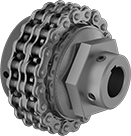
Protect shafts, motors, and gear boxes from damage that’s caused by torque overload from machine jams and emergency stops. If your set torque is exceeded, these couplings will disengage and then automatically re-engage once the torque is back within range. They handle more than five times as much torque as our other torque-limiting flexible shaft couplings. Connect them to your shafts with the included set screws, which bite into the shaft or shaft and key for a secure hold.
Single-spring couplings let you make finer torque adjustments than the double-spring couplings, but can only withstand half as much torque.
Double-spring couplings handle twice as much torque as the single-spring couplings, but are not the best for making precise adjustments at low torques.
Couplings for keyed shafts have keyways that are cut to standard ANSI dimensions, so they’ll fit snugly on ANSI keyed shafts to eliminate slipping during starts and stops.
![]() For technical drawings and 3-D models, click on a part number.
For technical drawings and 3-D models, click on a part number.
Misalignment Capability | Roller Chain | ||||||||||||
|---|---|---|---|---|---|---|---|---|---|---|---|---|---|
| For Shaft Dia. | Max. Torque, ft.-lbs. | Max. Speed, rpm | Parallel | Angular | OD | Overall Lg. | Keyway Wd. × Keyway Dp. | Hub Material | Torque-Limiting Direction | Standard | Trade Size | Each | |
Single Spring | |||||||||||||
For Keyed Shafts | |||||||||||||
| 5/8" × 5/8" | 25 | 1,800 | 0.01" | 3° | 2 3/4" | 2 1/4" | 3/16" × 3/32" 3/16" × 3/32" | Steel | Clockwise and Counterclockwise | ANSI | 35-2 | 00000000 | 0000000 |
| 5/8" × 3/4" | 25 | 1,800 | 0.01" | 3° | 2 3/4" | 2 1/4" | 3/16" × 3/32" 3/16" × 3/32" | Steel | Clockwise and Counterclockwise | ANSI | 35-2 | 00000000 | 000000 |
| 3/4" × 3/4" | 25 | 1,800 | 0.01" | 3° | 2 3/4" | 2 1/4" | 3/16" × 3/32" 3/16" × 3/32" | Steel | Clockwise and Counterclockwise | ANSI | 35-2 | 00000000 | 000000 |
| 1" × 1" | 75 | 1,800 | 0.01" | 3° | 3 11/16" | 2 13/16" | 1/4" × 1/8" 1/4" × 1/8" | Steel | Clockwise and Counterclockwise | ANSI | 40-2 | 00000000 | 000000 |
| 12mm × 12mm | 25 | 1,800 | 0.01" | 3° | 2 3/4" | 2 1/4" | 4mm × 2mm 4mm × 2mm | Steel | Clockwise and Counterclockwise | ANSI | 35-2 | 00000000 | 000000 |
| 12mm × 15mm | 25 | 1,800 | 0.01" | 3° | 2 3/4" | 2 1/4" | 4mm × 2mm 5mm × 2.5mm | Steel | Clockwise and Counterclockwise | ANSI | 35-2 | 00000000 | 000000 |
| 15mm × 15mm | 25 | 1,800 | 0.01" | 3° | 2 3/4" | 2 1/4" | 5mm × 2.5mm 5mm × 2.5mm | Steel | Clockwise and Counterclockwise | ANSI | 35-2 | 00000000 | 000000 |
| 15mm × 20mm | 75 | 1,800 | 0.01" | 3° | 3 11/16" | 2 13/16" | 5mm × 2.5mm 6mm × 3mm | Steel | Clockwise and Counterclockwise | ANSI | 40-2 | 00000000 | 000000 |
| 20mm × 20mm | 75 | 1,800 | 0.01" | 3° | 3 11/16" | 2 13/16" | 6mm × 3mm 6mm × 3mm | Steel | Clockwise and Counterclockwise | ANSI | 40-2 | 00000000 | 000000 |
| 20mm × 25mm | 75 | 1,800 | 0.01" | 3° | 3 11/16" | 2 13/16" | 6mm × 3mm 8mm × 4mm | Steel | Clockwise and Counterclockwise | ANSI | 40-2 | 00000000 | 000000 |
| 25mm × 25mm | 75 | 1,800 | 0.01" | 3° | 3 11/16" | 2 13/16" | 8mm × 4mm 8mm × 4mm | Steel | Clockwise and Counterclockwise | ANSI | 40-2 | 00000000 | 000000 |
For Round Shaft × For Keyed Shaft | |||||||||||||
| 1/2" × 5/8" | 25 | 1,800 | 0.01" | 3° | 2 3/4" | 2 1/4" | 3/16" × 3/32" | Steel | Clockwise and Counterclockwise | ANSI | 35-2 | 00000000 | 000000 |
| 1/2" × 3/4" | 25 | 1,800 | 0.01" | 3° | 2 3/4" | 2 1/4" | 3/16" × 3/32" | Steel | Clockwise and Counterclockwise | ANSI | 35-2 | 00000000 | 000000 |
For Round Shafts | |||||||||||||
| 1/2" × 1/2" | 25 | 1,800 | 0.01" | 3° | 2 3/4" | 2 1/4" | __ | Steel | Clockwise and Counterclockwise | ANSI | 35-2 | 00000000 | 000000 |
Double Spring | |||||||||||||
For Keyed Shafts | |||||||||||||
| 5/8" × 5/8" | 50 | 1,800 | 0.01" | 3° | 2 3/4" | 2 1/4" | 3/16" × 3/32" 3/16" × 3/32" | Steel | Clockwise and Counterclockwise | ANSI | 35-2 | 00000000 | 000000 |
| 5/8" × 3/4" | 50 | 1,800 | 0.01" | 3° | 2 3/4" | 2 1/4" | 3/16" × 3/32" 3/16" × 3/32" | Steel | Clockwise and Counterclockwise | ANSI | 35-2 | 00000000 | 000000 |
| 3/4" × 3/4" | 50 | 1,800 | 0.01" | 3° | 2 3/4" | 2 1/4" | 3/16" × 3/32" 3/16" × 3/32" | Steel | Clockwise and Counterclockwise | ANSI | 35-2 | 00000000 | 000000 |
| 1" × 1" | 150 | 1,800 | 0.01" | 3° | 3 11/16" | 2 13/16" | 1/4" × 1/8" 1/4" × 1/8" | Steel | Clockwise and Counterclockwise | ANSI | 40-2 | 00000000 | 000000 |
| 12mm × 12mm | 50 | 1,800 | 0.01" | 3° | 2 3/4" | 2 1/4" | 4mm × 2mm 4mm × 2mm | Steel | Clockwise and Counterclockwise | ANSI | 35-2 | 00000000 | 000000 |
| 12mm × 15mm | 50 | 1,800 | 0.01" | 3° | 2 3/4" | 2 1/4" | 4mm × 2mm 5mm × 2.5mm | Steel | Clockwise and Counterclockwise | ANSI | 35-2 | 00000000 | 000000 |
| 15mm × 15mm | 50 | 1,800 | 0.01" | 3° | 2 3/4" | 2 1/4" | 5mm × 2.5mm 5mm × 2.5mm | Steel | Clockwise and Counterclockwise | ANSI | 35-2 | 00000000 | 000000 |
| 15mm × 20mm | 150 | 1,800 | 0.01" | 3° | 3 11/16" | 2 13/16" | 5mm × 2.5mm 6mm × 3mm | Steel | Clockwise and Counterclockwise | ANSI | 40-2 | 00000000 | 000000 |
| 20mm × 20mm | 150 | 1,800 | 0.01" | 3° | 3 11/16" | 2 13/16" | 6mm × 3mm 6mm × 3mm | Steel | Clockwise and Counterclockwise | ANSI | 40-2 | 00000000 | 000000 |
| 20mm × 25mm | 150 | 1,800 | 0.01" | 3° | 3 11/16" | 2 13/16" | 6mm × 3mm 8mm × 4mm | Steel | Clockwise and Counterclockwise | ANSI | 40-2 | 00000000 | 000000 |
| 25mm × 25mm | 150 | 1,800 | 0.01" | 3° | 3 11/16" | 2 13/16" | 8mm × 4mm 8mm × 4mm | Steel | Clockwise and Counterclockwise | ANSI | 40-2 | 00000000 | 000000 |
For Round Shaft × For Keyed Shaft | |||||||||||||
| 1/2" × 5/8" | 50 | 1,800 | 0.01" | 3° | 2 3/4" | 2 1/4" | 3/16" × 3/32" | Steel | Clockwise and Counterclockwise | ANSI | 35-2 | 00000000 | 000000 |
| 1/2" × 3/4" | 50 | 1,800 | 0.01" | 3° | 2 3/4" | 2 1/4" | 3/16" × 3/32" | Steel | Clockwise and Counterclockwise | ANSI | 35-2 | 00000000 | 000000 |
For Round Shafts | |||||||||||||
| 1/2" × 1/2" | 50 | 1,800 | 0.01" | 3° | 2 3/4" | 2 1/4" | __ | Steel | Clockwise and Counterclockwise | ANSI | 35-2 | 00000000 | 000000 |
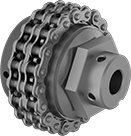
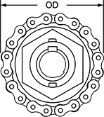
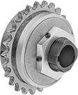
Torque Limiters for Chain and Belt Drives
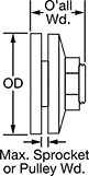
Prevent damage from overloading. When overloaded, these limiters cause your sprocket or pulley to slip. Once the overload is removed, the limiters automatically reset. Set the torque within the range listed. Friction discs are between the hub and pressure plate.
Double-spring limiters have a second spring for handling nearly twice the torque of single-spring limiters.
Optional sprockets are designed specifically to fit their corresponding limiters. These hubless sprockets are not interchangeable.
![]() For technical drawings and 3-D models, click on a part number.
For technical drawings and 3-D models, click on a part number.
Torque Limiters | |||||||||||||||||||
|---|---|---|---|---|---|---|---|---|---|---|---|---|---|---|---|---|---|---|---|
Keyway | Torque | Optional Sprockets | Replacement Friction Discs for Torque Limiters | Replacement Bushings for Optional Sprockets | |||||||||||||||
| For Shaft Dia. | OD | O'all Wd. | Wd. | Dp. | For Max. Sprocket or Pulley Wd. | Friction Disc Thick. | Min., ft.-lbs. | Max., ft.-lbs. | Hub Material | Each | For Roller Chain Trade Size | Each | Each | For Roller Chain Trade Size | Each | ||||
Single Spring | |||||||||||||||||||
| 1/4" | 1 5/16" | 1 3/8" | 1/16" | 1/32" | 11/32" | 1/8" | 1 | 6 | Steel | 00000000 | 000000 | 0000000 | 000000 | 0000000 | 00000 | __ | 000000 | 00 | |
| 5/16" | 1 5/16" | 1 3/8" | 3/32" | 3/64" | 11/32" | 1/8" | 1 | 6 | Steel | 00000000 | 00000 | 0000000 | 00000 | 0000000 | 0000 | __ | 000000 | 00 | |
| 3/8" | 1 5/16" | 1 3/8" | 3/32" | 3/64" | 11/32" | 1/8" | 1 | 6 | Steel | 00000000 | 00000 | 0000000 | 00000 | 0000000 | 0000 | __ | 000000 | 00 | |
| 3/8" | 2 1/4" | 2" | 3/32" | 3/64" | 1/2" | 1/8" | 5 | 35 | Steel | 00000000 | 000000 | 0000000 | 00000 | 0000000 | 00000 | __ | 000000 | 00 | |
| 1/2" | 2 1/4" | 2" | 1/8" | 1/16" | 1/2" | 1/8" | 5 | 35 | Steel | 0000000 | 000000 | 0000000 | 00000 | 0000000 | 00000 | __ | 000000 | 00 | |
| 1/2" | 2 1/2" | 1 3/4" | 1/8" | 1/16" | 11/32" | 1/8" | 25 | 60 | Steel | 00000000 | 00000 | 0000000 | 00000 | 0000000 | 0000 | 000000 | 00000 | ||
| 1/2" | 3 3/8" | 2 1/8" | 1/8" | 1/16" | 1/2" | 1/8" | 11 | 100 | Steel | 00000000 | 000000 | 0000000 | 00000 | 0000000 | 00000 | __ | 000000 | 00 | |
| 5/8" | 2 1/4" | 2" | 3/16" | 3/32" | 1/2" | 1/8" | 5 | 35 | Steel | 0000000 | 000000 | 0000000 | 00000 | 0000000 | 00000 | __ | 000000 | 00 | |
| 5/8" | 2 1/2" | 1 3/4" | 3/16" | 3/32" | 11/32" | 1/8" | 25 | 60 | Steel | 00000000 | 00000 | 0000000 | 00000 | 0000000 | 0000 | 000000 | 0000 | ||
| 5/8" | 3 3/8" | 2 1/8" | 3/16" | 3/32" | 1/2" | 1/8" | 11 | 100 | Steel | 0000000 | 000000 | 0000000 | 00000 | 0000000 | 00000 | __ | 000000 | 00 | |
| 3/4" | 2 1/4" | 2" | 3/16" | 3/32" | 1/2" | 1/8" | 5 | 35 | Steel | 0000000 | 000000 | 0000000 | 00000 | 0000000 | 00000 | __ | 000000 | 00 | |
| 3/4" | 2 1/2" | 1 3/4" | 3/16" | 3/32" | 11/32" | 1/8" | 25 | 60 | Steel | 00000000 | 00000 | 0000000 | 00000 | 0000000 | 0000 | 000000 | 0000 | ||
| 3/4" | 3 3/8" | 2 1/8" | 3/16" | 3/32" | 1/2" | 1/8" | 11 | 100 | Steel | 0000000 | 000000 | 0000000 | 00000 | 0000000 | 00000 | __ | 000000 | 00 | |
| 3/4" | 3 1/2" | 2 3/16" | 3/16" | 3/32" | 1/2" | 1/8" | 50 | 120 | Steel | 00000000 | 000000 | 0000000 | 00000 | 0000000 | 00000 | 000000 | 0000 | ||
| 3/4" | 4 1/2" | 2 7/8" | 3/16" | 3/32" | 7/8" | 1/8" | 18 | 190 | Steel | 00000000 | 000000 | 0000000 | 00000 | 0000000 | 00000 | __ | 000000 | 00 | |
| 7/8" | 2 1/2" | 1 3/4" | 3/16" | 3/32" | 11/32" | 1/8" | 25 | 60 | Steel | 00000000 | 00000 | 0000000 | 00000 | 0000000 | 0000 | 000000 | 0000 | ||
| 7/8" | 3 3/8" | 2 1/8" | 3/16" | 3/32" | 1/2" | 1/8" | 11 | 100 | Steel | 0000000 | 000000 | 0000000 | 00000 | 0000000 | 00000 | __ | 000000 | 00 | |
| 7/8" | 3 1/2" | 2 3/16" | 3/16" | 3/32" | 1/2" | 1/8" | 50 | 120 | Steel | 00000000 | 000000 | 0000000 | 00000 | 0000000 | 00000 | 000000 | 0000 | ||
| 1" | 2 1/2" | 1 3/4" | 1/4" | 1/8" | 11/32" | 1/8" | 25 | 60 | Steel | 00000000 | 00000 | 0000000 | 00000 | 0000000 | 0000 | 000000 | 0000 | ||
| 1" | 3 3/8" | 2 1/8" | 1/4" | 1/8" | 1/2" | 1/8" | 11 | 100 | Steel | 0000000 | 000000 | 0000000 | 00000 | 0000000 | 00000 | __ | 000000 | 00 | |
| 1" | 3 1/2" | 2 3/16" | 1/4" | 1/8" | 1/2" | 1/8" | 50 | 120 | Steel | 00000000 | 000000 | 0000000 | 00000 | 0000000 | 00000 | 000000 | 0000 | ||
| 1" | 4 1/2" | 2 7/8" | 1/4" | 1/8" | 7/8" | 1/8" | 18 | 190 | Steel | 00000000 | 000000 | 0000000 | 00000 | 0000000 | 00000 | __ | 000000 | 00 | |
| 1" | 5" | 2 7/8" | 1/4" | 1/8" | 5/8" | 1/8" | 90 | 250 | Steel | 00000000 | 000000 | 0000000 | 00000 | 0000000 | 00000 | 000000 | 0000 | ||
| 1" | 6" | 3" | 1/4" | 1/8" | 13/16" | 1/8" | 24 | 320 | Steel | 00000000 | 000000 | 0000000 | 00000 | 0000000 | 00000 | __ | 000000 | 00 | |
| 1 1/8" | 4 1/2" | 2 7/8" | 1/4" | 1/8" | 7/8" | 1/8" | 18 | 190 | Steel | 00000000 | 000000 | 0000000 | 00000 | 0000000 | 00000 | __ | 000000 | 00 | |
| 1 1/8" | 5" | 2 7/8" | 1/4" | 1/8" | 5/8" | 1/8" | 90 | 250 | Steel | 00000000 | 000000 | 0000000 | 00000 | 0000000 | 00000 | 000000 | 0000 | ||
| 1 3/16" | 5" | 2 7/8" | 1/4" | 1/8" | 5/8" | 1/8" | 90 | 250 | Steel | 00000000 | 000000 | 0000000 | 00000 | 0000000 | 00000 | 000000 | 0000 | ||
| 1 1/4" | 3 1/2" | 2 3/16" | 1/4" | 1/8" | 1/2" | 1/8" | 50 | 120 | Steel | 00000000 | 000000 | 0000000 | 00000 | 0000000 | 00000 | 000000 | 0000 | ||
| 1 1/4" | 4 1/2" | 2 7/8" | 1/4" | 1/8" | 7/8" | 1/8" | 18 | 190 | Steel | 00000000 | 000000 | 0000000 | 00000 | 0000000 | 00000 | __ | 000000 | 00 | |
| 1 1/4" | 5" | 2 7/8" | 1/4" | 1/8" | 5/8" | 1/8" | 90 | 250 | Steel | 00000000 | 000000 | 0000000 | 00000 | 0000000 | 00000 | 000000 | 0000 | ||
| 1 1/4" | 6" | 3" | 1/4" | 1/8" | 13/16" | 1/8" | 24 | 320 | Steel | 00000000 | 000000 | 0000000 | 00000 | 0000000 | 00000 | __ | 000000 | 00 | |
| 1 3/8" | 4 1/2" | 2 7/8" | 5/16" | 5/32" | 7/8" | 1/8" | 18 | 190 | Steel | 00000000 | 000000 | 0000000 | 00000 | 0000000 | 00000 | __ | 000000 | 00 | |
| 1 3/8" | 5" | 2 7/8" | 5/16" | 5/32" | 5/8" | 1/8" | 90 | 250 | Steel | 00000000 | 000000 | 0000000 | 00000 | 0000000 | 00000 | 000000 | 0000 | ||
| 1 3/8" | 6" | 3" | 5/16" | 5/32" | 13/16" | 1/8" | 24 | 320 | Steel | 00000000 | 000000 | 0000000 | 00000 | 0000000 | 00000 | __ | 000000 | 00 | |
| 1 7/16" | 5" | 2 7/8" | 3/8" | 3/16" | 5/8" | 1/8" | 90 | 250 | Steel | 00000000 | 000000 | 0000000 | 00000 | 0000000 | 00000 | 000000 | 0000 | ||
| 1 7/16" | 6" | 3" | 3/8" | 3/16" | 13/16" | 1/8" | 24 | 320 | Steel | 00000000 | 000000 | 0000000 | 00000 | 0000000 | 00000 | __ | 000000 | 00 | |
| 1 1/2" | 5" | 2 7/8" | 3/8" | 3/16" | 5/8" | 1/8" | 90 | 250 | Steel | 00000000 | 000000 | 0000000 | 00000 | 0000000 | 00000 | 000000 | 0000 | ||
| 1 1/2" | 6" | 3" | 3/8" | 3/16" | 13/16" | 1/8" | 24 | 320 | Steel | 00000000 | 000000 | 0000000 | 00000 | 0000000 | 00000 | __ | 000000 | 00 | |
| 1 5/8" | 5" | 2 7/8" | 3/8" | 3/16" | 5/8" | 1/8" | 90 | 250 | Steel | 00000000 | 000000 | 0000000 | 00000 | 0000000 | 00000 | 000000 | 0000 | ||
| 1 5/8" | 6" | 3" | 3/8" | 3/16" | 13/16" | 1/8" | 24 | 320 | Steel | 00000000 | 000000 | 0000000 | 00000 | 0000000 | 00000 | __ | 000000 | 00 | |
Double Spring | |||||||||||||||||||
| 1/4" | 1 5/16" | 1 3/8" | 1/16" | 1/32" | 5/16" | 1/8" | 2 | 12 | Steel | 00000000 | 00000 | 0000000 | 00000 | 0000000 | 0000 | __ | 000000 | 00 | |
| 5/16" | 1 5/16" | 1 3/8" | 3/32" | 3/64" | 5/16" | 1/8" | 2 | 12 | Steel | 00000000 | 00000 | 0000000 | 00000 | 0000000 | 0000 | __ | 000000 | 00 | |
| 3/8" | 1 5/16" | 1 3/8" | 3/32" | 3/64" | 5/16" | 1/8" | 2 | 12 | Steel | 00000000 | 00000 | 0000000 | 00000 | 0000000 | 0000 | __ | 000000 | 00 | |
| 3/8" | 2 1/4" | 2" | 3/32" | 3/64" | 15/32" | 1/8" | 7 | 50 | Steel | 00000000 | 000000 | 0000000 | 00000 | 0000000 | 00000 | __ | 000000 | 00 | |
| 1/2" | 2 1/4" | 2" | 1/8" | 1/16" | 15/32" | 1/8" | 7 | 50 | Steel | 0000000 | 000000 | 0000000 | 00000 | 0000000 | 00000 | __ | 000000 | 00 | |
| 1/2" | 2 1/2" | 1 3/4" | 1/8" | 1/16" | 11/32" | 1/8" | 30 | 95 | Steel | 00000000 | 000000 | 0000000 | 00000 | 0000000 | 0000 | 000000 | 0000 | ||
| 1/2" | 3 3/8" | 2 1/8" | 1/8" | 1/16" | 7/16" | 1/8" | 13 | 175 | Steel | 00000000 | 000000 | 0000000 | 00000 | 0000000 | 00000 | __ | 000000 | 00 | |
| 5/8" | 2 1/4" | 2" | 3/16" | 3/32" | 15/32" | 1/8" | 7 | 50 | Steel | 0000000 | 000000 | 0000000 | 00000 | 0000000 | 00000 | __ | 000000 | 00 | |
| 5/8" | 2 1/2" | 1 3/4" | 3/16" | 3/32" | 11/32" | 1/8" | 30 | 95 | Steel | 00000000 | 000000 | 0000000 | 00000 | 0000000 | 0000 | 000000 | 0000 | ||
| 5/8" | 3 3/8" | 2 1/8" | 3/16" | 3/32" | 7/16" | 1/8" | 13 | 175 | Steel | 00000000 | 000000 | 0000000 | 00000 | 0000000 | 00000 | __ | 000000 | 00 | |
| 3/4" | 2 1/4" | 2" | 3/16" | 3/32" | 15/32" | 1/8" | 7 | 50 | Steel | 0000000 | 000000 | 0000000 | 00000 | 0000000 | 00000 | __ | 000000 | 00 | |
| 3/4" | 2 1/2" | 1 3/4" | 3/16" | 3/32" | 11/32" | 1/8" | 30 | 95 | Steel | 00000000 | 000000 | 0000000 | 00000 | 0000000 | 0000 | 000000 | 0000 | ||
| 3/4" | 3 3/8" | 2 1/8" | 3/16" | 3/32" | 7/16" | 1/8" | 13 | 175 | Steel | 0000000 | 000000 | 0000000 | 00000 | 0000000 | 00000 | __ | 000000 | 00 | |
| 3/4" | 3 1/2" | 2 3/16" | 3/16" | 3/32" | 1/2" | 1/8" | 60 | 190 | Steel | 00000000 | 000000 | 0000000 | 00000 | 0000000 | 00000 | 000000 | 0000 | ||
| 3/4" | 4 1/2" | 2 7/8" | 3/16" | 3/32" | 13/16" | 1/8" | 20 | 285 | Steel | 00000000 | 000000 | 0000000 | 00000 | 0000000 | 00000 | __ | 000000 | 00 | |
| 7/8" | 2 1/2" | 1 3/4" | 3/16" | 3/32" | 11/32" | 1/8" | 30 | 95 | Steel | 00000000 | 000000 | 0000000 | 00000 | 0000000 | 0000 | 000000 | 0000 | ||
| 7/8" | 3 3/8" | 2 1/8" | 3/16" | 3/32" | 7/16" | 1/8" | 13 | 175 | Steel | 00000000 | 000000 | 0000000 | 00000 | 0000000 | 00000 | __ | 000000 | 00 | |
| 7/8" | 3 1/2" | 2 3/16" | 3/16" | 3/32" | 1/2" | 1/8" | 60 | 190 | Steel | 00000000 | 000000 | 0000000 | 00000 | 0000000 | 00000 | 000000 | 0000 | ||
| 1" | 2 1/2" | 1 3/4" | 1/4" | 1/8" | 11/32" | 1/8" | 30 | 95 | Steel | 00000000 | 000000 | 0000000 | 00000 | 0000000 | 0000 | 000000 | 0000 | ||
| 1" | 3 3/8" | 2 1/8" | 1/4" | 1/8" | 7/16" | 1/8" | 13 | 175 | Steel | 0000000 | 000000 | 0000000 | 00000 | 0000000 | 00000 | __ | 000000 | 00 | |
| 1" | 3 1/2" | 2 3/16" | 1/4" | 1/8" | 1/2" | 1/8" | 60 | 190 | Steel | 00000000 | 000000 | 0000000 | 00000 | 0000000 | 00000 | 000000 | 0000 | ||
| 1" | 4 1/2" | 2 7/8" | 1/4" | 1/8" | 13/16" | 1/8" | 20 | 285 | Steel | 00000000 | 000000 | 0000000 | 00000 | 0000000 | 00000 | __ | 000000 | 00 | |
| 1" | 5" | 2 7/8" | 1/4" | 1/8" | 5/8" | 1/8" | 120 | 400 | Steel | 00000000 | 000000 | 0000000 | 00000 | 0000000 | 00000 | 000000 | 0000 | ||
| 1" | 6" | 3" | 1/4" | 1/8" | 3/4" | 1/8" | 26 | 440 | Steel | 00000000 | 000000 | 0000000 | 00000 | 0000000 | 00000 | __ | 000000 | 00 | |
| 1 1/8" | 4 1/2" | 2 7/8" | 1/4" | 1/8" | 13/16" | 1/8" | 20 | 285 | Steel | 00000000 | 000000 | 0000000 | 00000 | 0000000 | 00000 | __ | 000000 | 00 | |
| 1 1/8" | 5" | 2 7/8" | 1/4" | 1/8" | 5/8" | 1/8" | 120 | 400 | Steel | 00000000 | 000000 | 0000000 | 00000 | 0000000 | 00000 | 000000 | 0000 | ||
| 1 3/16" | 5" | 2 7/8" | 1/4" | 1/8" | 5/8" | 1/8" | 120 | 400 | Steel | 00000000 | 000000 | 0000000 | 00000 | 0000000 | 00000 | 000000 | 0000 | ||
| 1 1/4" | 3 1/2" | 2 3/16" | 1/4" | 1/8" | 1/2" | 1/8" | 60 | 190 | Steel | 00000000 | 000000 | 0000000 | 00000 | 0000000 | 00000 | 000000 | 0000 | ||
| 1 1/4" | 4 1/2" | 2 7/8" | 1/4" | 1/8" | 13/16" | 1/8" | 20 | 285 | Steel | 00000000 | 000000 | 0000000 | 00000 | 0000000 | 00000 | __ | 000000 | 00 | |
| 1 1/4" | 5" | 2 7/8" | 1/4" | 1/8" | 5/8" | 1/8" | 120 | 400 | Steel | 00000000 | 000000 | 0000000 | 00000 | 0000000 | 00000 | 000000 | 0000 | ||
| 1 1/4" | 6" | 3" | 1/4" | 1/8" | 3/4" | 1/8" | 26 | 440 | Steel | 00000000 | 000000 | 0000000 | 00000 | 0000000 | 00000 | __ | 000000 | 00 | |
| 1 3/8" | 4 1/2" | 2 7/8" | 5/16" | 5/32" | 13/16" | 1/8" | 20 | 285 | Steel | 00000000 | 000000 | 0000000 | 00000 | 0000000 | 00000 | __ | 000000 | 00 | |
| 1 3/8" | 5" | 2 7/8" | 5/16" | 5/32" | 5/8" | 1/8" | 120 | 400 | Steel | 00000000 | 000000 | 0000000 | 00000 | 0000000 | 00000 | 000000 | 0000 | ||
| 1 3/8" | 6" | 3" | 5/16" | 5/32" | 3/4" | 1/8" | 26 | 440 | Steel | 00000000 | 000000 | 0000000 | 00000 | 0000000 | 00000 | __ | 000000 | 00 | |
| 1 7/16" | 5" | 2 7/8" | 3/8" | 3/16" | 5/8" | 1/8" | 120 | 400 | Steel | 00000000 | 000000 | 0000000 | 00000 | 0000000 | 00000 | 000000 | 0000 | ||
| 1 7/16" | 6" | 3" | 3/8" | 3/16" | 3/4" | 1/8" | 26 | 440 | Steel | 00000000 | 000000 | 0000000 | 00000 | 0000000 | 00000 | __ | 000000 | 00 | |
| 1 1/2" | 5" | 2 7/8" | 3/8" | 3/16" | 5/8" | 1/8" | 120 | 400 | Steel | 00000000 | 000000 | 0000000 | 00000 | 0000000 | 00000 | 000000 | 0000 | ||
| 1 1/2" | 6" | 3" | 3/8" | 3/16" | 3/4" | 1/8" | 26 | 440 | Steel | 00000000 | 000000 | 0000000 | 00000 | 0000000 | 00000 | __ | 000000 | 00 | |
| 1 5/8" | 5" | 2 7/8" | 3/8" | 3/16" | 5/8" | 1/8" | 120 | 400 | Steel | 00000000 | 000000 | 0000000 | 00000 | 0000000 | 00000 | 000000 | 0000 | ||
| 1 5/8" | 6" | 3" | 3/8" | 3/16" | 3/4" | 1/8" | 26 | 440 | Steel | 00000000 | 000000 | 0000000 | 00000 | 0000000 | 00000 | __ | 000000 | 00 | |
Torque-Limiting Flexible Shaft Couplings with Alarm
If they exceed maximum torque, these couplings disengage, sound an alarm, and then automatically re-engage once the overtorque condition is eliminated. Torque can be adjusted ±10% of the factory setting. No lubrication is required. Fasten to your shaft by tightening the set screws, which bite into the shaft to hold it.
![]() For technical drawings and 3-D models, click on a part number.
For technical drawings and 3-D models, click on a part number.
Misalignment Capability | ||||||||||||
|---|---|---|---|---|---|---|---|---|---|---|---|---|
| For Shaft Dia. | Max. Speed, rpm | Parallel | Angular | OD | Overall Lg. | Keyway Wd. × Keyway Dp. | Material | Center Material | Torque-Limiting Direction | Choose a Max. Torque, in.-lbs. | Each | |
For Keyed Shafts | ||||||||||||
| 5/8" | 1,800 | 0.031" | 6° | 3 1/2" | 3" | 3/16" × 3/32" | 6061 Aluminum | Steel | Clockwise and Counterclockwise | 0000000 | 000000 | |
| 3/4" | 1,800 | 0.031" | 6° | 3 1/2" | 3" | 3/16" × 3/32" | 6061 Aluminum | Steel | Clockwise and Counterclockwise | 0000000 | 00000 | |
| 7/8" | 1,800 | 0.031" | 6° | 3 1/2" | 3" | 3/16" × 3/32" | 6061 Aluminum | Steel | Clockwise and Counterclockwise | 0000000 | 00000 | |
| 1" | 1,800 | 0.031" | 6° | 3 1/2" | 3" | 1/4" × 1/8" | 6061 Aluminum | Steel | Clockwise and Counterclockwise | 0000000 | 00000 | |
For Round Shafts | ||||||||||||
| 1/2" | 1,800 | 0.031" | 6° | 3 1/2" | 3" | __ | 6061 Aluminum | Steel | Clockwise and Counterclockwise | 0000000 | 00000 | |