


Filter by
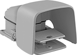
Gear Box Input Connection


Component
Input Voltage
Transmitter Type
Electrical Connection
Encoder Output Channel Type
Mount Type
Actuator Style

For Maximum Shaft Speed
Encoder Output Signal
Housing Material
DFARS Specialty Metals
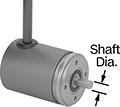
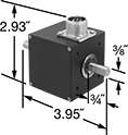
Compact Rotary Encoders
Incremental Optical Encoders with Shaft
 |  |
Wire Lead Connection—NPN Open Collector | 5-Pole Micro M12 Plug-In Connection—IO-Link |
Incremental transmitters track how much a rotating shaft has turned relative to a reference point. They need to be reset after a power loss.
Transmitters with a shaft connect to a motor’s shaft with a flexible shaft coupling to fit different diameters.
NPN Open Collector—Transmitters with an NPN open collector pair with a resistor. Use these transmitters with a controller that has quadrature detection to get a 4X resolution increase.
IO-Link Communication Protocol—Transmitters with IO-Link let you set their resolution remotely when connected to a PLC, a human-machine interface (HMI), or a computer.
IP64 Enclosure Rating and IP65 Enclosure Rating—IP-rated transmitters are protected from dust and water.
Encoders | Connectors | ||||||||||||||||||
|---|---|---|---|---|---|---|---|---|---|---|---|---|---|---|---|---|---|---|---|
Mounting Holes | |||||||||||||||||||
Shaft Dia. | Rotary Encoder Type | Input Voltage, V DC | Max. Input Current, mA | Output Current, mA | Encoder Output Channel Type | For Max. Shaft Speed, rpm | Body Material | Housing Material | Enclosure Rating | No. of | Thread Size | Fasteners Included | Choose a Resolution | Each | Each | ||||
Wire Lead Connection—NPN Open Collector | |||||||||||||||||||
| 1/4" | Single Turn | 5 to 28 | 65 | 20 | Quadrature with Index | 8,000 | Aluminum | Plastic | IP64 | 3 | M3 × 0.5 mm | No | 500, 1,000, 2,000, 2,500 | 9749T3 | 0000000 | ——— | 0 | ||
5-Pole Micro M12 Plug-In Connection—IO-Link | |||||||||||||||||||
| 6 mm | Single Turn | 5 to 30 | 150 | 50 | — | 12,000 | Stainless Steel | Aluminum | IP65 | 3 | M4 × 0.7 mm | No | 1 to 10,000 | 9749T519 | 000000 | 4490N15 | 000000 | ||
| 10 mm | Single Turn | 5 to 30 | 150 | 50 | — | 12,000 | Stainless Steel | Aluminum | IP65 | 3 | M4 × 0.7 mm | No | 1 to 10,000 | 9749T521 | 000000 | 4490N15 | 00000 | ||
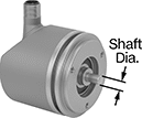
Incremental Optical Encoders with Shaft Opening
 |  |
Wire Lead Connection—NPN Open Collector | 5-Pole Micro M12 Plug-In Connection—IO-Link |
Incremental transmitters track how much a rotating shaft has turned relative to a reference point. They need to be reset after a power loss.
Transmitters with a shaft opening slide onto your motor's shaft. Their mounting plate flexes to compensate for your motor's vibration.
NPN Open Collector—Transmitters with an NPN open collector pair with a resistor. Use these transmitters with a controller that has quadrature detection to get a 4X resolution increase.
IO-Link Communication Protocol—Transmitters with IO-Link let you set their resolution remotely when connected to a PLC, a human-machine interface (HMI), or a computer.
IP64 Enclosure Rating and IP65 Enclosure Rating—IP-rated transmitters are protected from dust and water.
Encoders | Connectors | ||||||||||||||||||||||
|---|---|---|---|---|---|---|---|---|---|---|---|---|---|---|---|---|---|---|---|---|---|---|---|
Mounting Holes | |||||||||||||||||||||||
For Shaft Dia. | Rotary Encoder Type | Input Voltage, V DC | Max. Input Current, mA | Output Current, mA | Encoder Output Channel Type | For Max. Shaft Speed, rpm | Body Material | Housing Material | Enclosure Rating | Mounting Plate Dia. | Mounting Plate Wd. | For Screw Size | No. of | Ctr.-to-Ctr. | Thread Size | Fasteners Included | Choose a Resolution | Each | Each | ||||
Wire Lead Connection—NPN Open Collector | |||||||||||||||||||||||
| 1/4" | Single Turn | 5 to 28 | 65 | 20 | Quadrature with Index | 8,000 | Aluminum | Plastic | IP64 | — | 2.16" | No. 6 | 2 | 1.81" | — | No | 500, 1,000, 2,000, 2,500 | 9749T1 | 0000000 | ——— | 0 | ||
| 3/8" | Single Turn | 5 to 28 | 65 | 20 | Quadrature with Index | 8,000 | Aluminum | Plastic | IP64 | — | 2.16" | No. 6 | 2 | 1.81" | — | No | 500, 1,000, 2,000, 2,500 | 9749T2 | 000000 | ——— | 0 | ||
5-Pole Micro M12 Plug-In Connection—IO-Link | |||||||||||||||||||||||
| 6 mm | Single Turn | 5 to 30 | 150 | 50 | — | 12,000 | Stainless Steel | Aluminum | IP65 | 1.43" | — | — | 4 | — | M2.5 × 0.5 mm | No | 1 to 10,000 | 9749T522 | 000000 | 4490N15 | 000000 | ||
| 10 mm | Single Turn | 5 to 30 | 150 | 50 | — | 12,000 | Stainless Steel | Aluminum | IP65 | 1.43" | — | — | 4 | — | M2.5 × 0.5 mm | No | 1 to 10,000 | 9749T523 | 000000 | 4490N15 | 00000 | ||
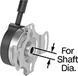
Absolute Optical Encoders with Shaft
| |
Wire Lead Connection—SSI | 5-Pole Micro M12 Plug-In Connection—IO-Link |
Absolute transmitters give you the exact position of the shaft, even after a power loss.
Transmitters with a shaft connect to a motor’s shaft with a flexible shaft coupling to fit different diameters.
IO-Link Communication Protocol—Transmitters with IO-Link let you set their resolution remotely when connected to a PLC, a human-machine interface (HMI), or a computer.
Multi-Turn Rotary Encoder—Multi-turn absolute transmitters count how many full turns a shaft makes. They’re often used to keep print rollers aligned over multiple rotations.
IP65 Enclosure Rating—IP-rated transmitters are protected from dust and water.
Encoders | Connectors | |||||||||||||||||
|---|---|---|---|---|---|---|---|---|---|---|---|---|---|---|---|---|---|---|
Mounting Holes | ||||||||||||||||||
Shaft Dia. | Rotary Encoder Type | Input Voltage, V DC | Max. Input Current, mA | Output Current, mA | For Max. Shaft Speed, rpm | Body Material | Housing Material | Enclosure Rating | No. of | Thread Size | Fasteners Included | Bit Resolution, bit | Each | Each | ||||
Wire Lead Connection—SSI | ||||||||||||||||||
| 1/4" | Single Turn | 5 to 32 | 50 | 100 | 12,000 | Aluminum | Stainless Steel | IP65 | 4 | M3 × 0.5 mm | No | 12 | 9749T515 | 0000000 | ——— | 0 | ||
| 1/4" | Multi-Turn | 5 to 32 | 50 | 100 | 12,000 | Aluminum | Stainless Steel | IP65 | 4 | M3 × 0.5 mm | No | 24 | 9749T516 | 000000 | ——— | 0 | ||
| 6 mm | Single Turn | 5 to 32 | 50 | 100 | 12,000 | Aluminum | Stainless Steel | IP65 | 4 | M3 × 0.5 mm | No | 12 | 9749T517 | 000000 | ——— | 0 | ||
| 6 mm | Multi-Turn | 5 to 32 | 50 | 100 | 12,000 | Aluminum | Stainless Steel | IP65 | 4 | M3 × 0.5 mm | No | 24 | 9749T518 | 000000 | ——— | 0 | ||
5-Pole Micro M12 Plug-In Connection—IO-Link | ||||||||||||||||||
| 6 mm | Multi-Turn | 18 to 30 | 75 | 50 | 12,000 | Stainless Steel | Aluminum | IP65 | 3 | M4 × 0.7 mm | No | 1 to 31 | 9749T525 | 000000 | 4490N15 | 000000 | ||
| 10 mm | Multi-Turn | 18 to 30 | 75 | 50 | 12,000 | Stainless Steel | Aluminum | IP65 | 3 | M4 × 0.7 mm | No | 1 to 31 | 9749T524 | 000000 | 4490N15 | 00000 | ||
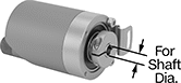
Absolute Optical Encoders with Shaft Opening
|
Wire Lead Connection—SSI |
Absolute transmitters give you the exact position of the shaft, even after a power loss.
Transmitters with a shaft opening slide onto your motor's shaft. Their mounting plate flexes to compensate for your motor's vibration.
Multi-Turn Rotary Encoder—Multi-turn absolute transmitters count how many full turns a shaft makes. They’re often used to keep print rollers aligned over multiple rotations.
Mounting Holes | |||||||||||||||||
|---|---|---|---|---|---|---|---|---|---|---|---|---|---|---|---|---|---|
For Shaft Dia. | Rotary Encoder Type | Input Voltage, V DC | Max. Input Current, mA | Output Current, mA | For Max. Shaft Speed, rpm | Body Material | Housing Material | Mounting Plate Wd. | For Screw Size | No. of | Ctr.-to-Ctr. | Fasteners Included | Bit Resolution, bit | Each | |||
Wire Lead Connection—SSI | |||||||||||||||||
| 1/4" | Single Turn | 5 to 24 | 100 | 420 | 8,000 | Aluminum | Plastic | 2.16" | No. 6 | 2 | 1.81" | No | 12 | 9749T511 | 0000000 | ||
| 1/4" | Multi-Turn | 5 to 24 | 100 | 420 | 8,000 | Aluminum | Plastic | 2.16" | No. 6 | 2 | 1.81" | No | 24 | 9749T512 | 000000 | ||
| 3/8" | Single Turn | 5 to 24 | 100 | 420 | 8,000 | Aluminum | Plastic | 2.16" | No. 6 | 2 | 1.81" | No | 12 | 9749T513 | 000000 | ||
| 3/8" | Multi-Turn | 5 to 24 | 100 | 420 | 8,000 | Aluminum | Plastic | 2.16" | No. 6 | 2 | 1.81" | No | 24 | 9749T514 | 000000 | ||
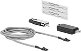
Rotary Encoder Kits
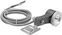 |  |
Shown with Wheel (Sold Separately) |
In addition to a transmitter, these kits include a 6 1/2-ft. cable and a mounting bracket. Also known as encoders, transmitters convert motion to an electrical signal to indicate distance, direction, and speed in process control and metering applications. These kits are commonly used to monitor the position or velocity of rotating equipment. You can also mount a wheel (not included) to measure distance in linear applications. Transmitters must be used with a controller that has quadrature detection to get a 4X resolution increase. Output channel Z is also known as an index channel.
Use a flexible shaft coupling (not included) to connect the transmitter shaft to a drive shaft.
For Counter Function | Encoder Output Channel | Resolution Increase | For Max. Shaft Speed, rpm | Input Voltage, V DC | Output Current, mA | Resistor Included | Body Material | Shaft Material | Fasteners Included | Fasteners Req. | For Mounting Screw Size | Choose a Resolution | Each | |||
|---|---|---|---|---|---|---|---|---|---|---|---|---|---|---|---|---|
Quadrature with Index Output Channel | ||||||||||||||||
| Up and Down | A, B, Z | 2X, 4X | 6,000 | 5 to 28 | 20 | No | Plastic | Stainless Steel | No | Yes | 1/4" | 500, 600, 1,000, 1,800, 2,500 | 16695T57 | 0000000 | ||
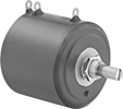
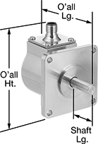
Rotary Encoders
Aluminum Body and Stainless Steel Shaft
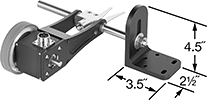 |  |
Shown with Wheel and Mounting Bracket (Both Sold Separately) |
Quadrature Output Channel—Transmitters with a quadrature output channel must be used with a controller that has quadrature detection to get a 4X resolution increase.
Shaft | Overall | Mounting Plate | Mounting Holes | |||||||||||||||
|---|---|---|---|---|---|---|---|---|---|---|---|---|---|---|---|---|---|---|
For Counter Function | Encoder Output Channel | Resolution Increase | For Max. Shaft Speed, rpm | Input Voltage, V DC | Coupling Req. | Dia. | Lg. | Lg. | Ht. | Lg. | Wd. | Ctr.-to-Ctr. | Thread Size | Choose a Resolution | Each | |||
Single Output Channel—250 mA Output Current | ||||||||||||||||||
| Up | A | 2X | 6,000 | 5 to 28 | Yes | 3/8" | 3/4" | 3.95" | 2.93" | 2 1/4" | 2 1/4" | 1.41" | 6-32 | 10, 60, 100, 120, 500, 600, 1,200 | 16695T46 | 0000000 | ||
Quadrature Output Channel—250 mA Output Current | ||||||||||||||||||
| Up and Down | A, B | 2X, 4X | 6,000 | 5 to 28 | Yes | 3/8" | 3/4" | 3.95" | 2.93" | 2 1/4" | 2 1/4" | 1.41" | 6-32 | 10, 60, 100, 120, 500, 600, 1,200 | 16695T47 | 000000 | ||
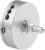
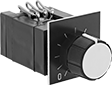
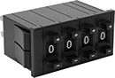
Potentiometers
 |  |  |  |
Style A | Style B | Style C | Style D |
 |  |  | |
Style E | Style F | Style G |
Potentiometers
| | | |
Style A | Style B | Style C | Style D |
Style A—Style A potentiometers are also known as gangable potentiometers. They can be linked to each other, so you can control multiple potentiometers from a single source.
IP65 Enclosure Rating—IP65 rated switches are protected against washdowns.
Shaft | ||||||||||||||||
|---|---|---|---|---|---|---|---|---|---|---|---|---|---|---|---|---|
Style | No. of Turns | Resolution | Wattage @ Voltage | For Panel Cutout Dia. | Dp. Behind Panel | Dia. | Dia. | Lg. | Housing Material | Wire Connection | No. of Terminals | Enclosure Rating | Choose a Maximum Resistance, kohm | Each | ||
| A | 3 | 33% | 1 W @ 224V AC | 7/16" | 3/4" | 7/8" | 1/4" | 1/2" | Plastic | Tab | 3 | IP40 | 1, 5, 10 | 7436K46 | 000000 | |
| B | 5 | 20% | 1.5 W @ 273V AC | 7/16" | 3/4" | 7/8" | 1/4" | 1/2" | Plastic | Tab | 3 | IP40 | 1, 5, 10 | 7436K34 | 00000 | |
| B | 10 | 10% | 2 W @ 325V AC | 7/16" | 1" | 7/8" | 1/4" | 1/2" | Plastic | Tab | 3 | IP65 | 1, 5, 10 | 7436K42 | 00000 | |
| B | 10 | 10% | 2 W @ 447V AC | 7/16" | 3/4" | 7/8" | 1/4" | 1/2" | Plastic | Tab | 3 | IP40 | 1, 5, 10 | 7436K32 | 00000 | |
| B | 10 | 10% | 2 W @ 450V AC | 7/16" | 3/4" | 7/8" | 1/4" | 1/2" | Plastic | Tab | 3 | IP40 | 1, 5, 10, 20 | 7436K31 | 00000 | |
| C | 1 | 100% | 1 W @ 300V AC | 7/16" | 7/16" | 7/8" | 1/4" | 1/2" | Plastic | Tab | 3 | IP40 | 1, 5, 10, 20 | 7436K37 | 00000 | |
| D | 10 | 10% | 5 W @ 1,000V AC | 7/16" | 1 3/4" | 1 13/16" | 1/4" | 1/2" | Plastic | Tab | 3 | IP40 | 1, 5, 10 | 7436K33 | 000000 | |
Potentiometers with Ball Bearings
| |
Style E | Style F |
Shaft | ||||||||||||||||
|---|---|---|---|---|---|---|---|---|---|---|---|---|---|---|---|---|
Style | No. of Turns | Resolution | Wattage @ Voltage | For Panel Cutout Dia. | Dp. Behind Panel | Dia. | Dia. | Lg. | Housing Material | Wire Connection | No. of Terminals | Enclosure Rating | Choose a Maximum Resistance, kohm | Each | ||
| E | 1 | 100% | 1 W @ 300V AC | — | 5/8" | 7/8" | 1/8" | 7/16" | Metal | Tab | 3 | IP50 | 1, 5, 10 | 7436K45 | 0000000 | |
| F | 1 | 100% | 2 W @ 350V AC | 7/16" | 5/8" | 2" | 1/4" | 3/8" | Plastic | Tab | 3 | IP40 | 5, 10 | 7436K44 | 000000 | |
Potentiometers with On/Off Switch
|
Style G |
Switching | Shaft | |||||||||||||||||
|---|---|---|---|---|---|---|---|---|---|---|---|---|---|---|---|---|---|---|
Style | No. of Turns | Resolution | Wattage @ Voltage | Current, amp | Voltage, V DC | For Panel Cutout Dia. | Dp. Behind Panel | Dia. | Dia. | Lg. | Housing Material | Wire Connection | No. of Terminals | Enclosure Rating | Choose a Maximum Resistance, kohm | Each | ||
| G | 1 | 100% | 0.125 W @ 350V AC | 1.5 | 12 | 3/16" | 1/4" | 7/16" | 1/8" | 5/16" | Metal | Tab | 5 | IP40 | 5, 10, 20, 25 | 3980T1 | 000000 | |
Programmable Rotary Encoders
Encoders with Shaft
 |
Transmitters with a shaft connect to motor shafts with a flexible shaft coupling, so they can be adapted to different diameters.
Shaft Dia. | Encoder Output Signal | Input Voltage, V DC | Max. Input Current, mA | Output Current, mA | For Max. Shaft Speed, rpm | Body Material | Housing Material | Enclosure Rating | Mounting Hole Thread Size | Fasteners Included | Resolution | Each | |||
|---|---|---|---|---|---|---|---|---|---|---|---|---|---|---|---|
Incremental Optical Encoder | |||||||||||||||
| 1/4" | Line Driver, NPN Open Collector, Push-Pull | 5 to 30 | 65 | 20 | 8,000 | Aluminum | Aluminum | IP67 | 10-32 | No | 1 to 65,536 | 9924N121 | 0000000 | ||
| 3/8" | Line Driver, NPN Open Collector, Push-Pull | 5 to 30 | 65 | 20 | 8,000 | Aluminum | Aluminum | IP67 | 10-32 | No | 1 to 65,536 | 9924N122 | 000000 | ||
 |
Data Connection | Each | ||
|---|---|---|---|
| USB-A | 9924N125 | 0000000 |
Encoders with Shaft Opening
 |
Transmitters with a shaft opening can be mounted anywhere along a motor shaft—just slide them on. They have a flexible mounting plate that compensates for shaft misalignment and vibration.
For Shaft Dia. | Encoder Output Signal | Input Voltage, V DC | Max. Input Current, mA | Output Current, mA | For Max. Shaft Speed, rpm | Body Material | Housing Material | Enclosure Rating | Mounting Plate Wd. | For Screw Size | Fasteners Included | Resolution | Each | |||
|---|---|---|---|---|---|---|---|---|---|---|---|---|---|---|---|---|
Incremental Optical Encoder | ||||||||||||||||
| 1/4" | Line Driver, NPN Open Collector, Push-Pull | 5 to 30 | 65 | 20 | 6,000 | Aluminum | Aluminum | IP67 | 2.83" | No. 6 | No | 1 to 65,536 | 9924N123 | 0000000 | ||
| 3/8" | Line Driver, NPN Open Collector, Push-Pull | 5 to 30 | 65 | 20 | 6,000 | Aluminum | Aluminum | IP67 | 2.83" | No. 6 | No | 1 to 65,536 | 9924N124 | 000000 | ||
|
Data Connection | Each | ||
|---|---|---|---|
| USB-A | 9924N125 | 0000000 |
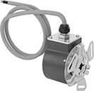
Sanitary Rotary Encoders
 |
Also known as encoders, these sanitary transmitters convey motion to an electrical signal that conveys distance, direction, and speed. They’re often used in control systems to automate servomotors, robotics, and assembly machines in sanitary environments such as food and pharmaceutical plants. Made of corrosion-resistant stainless steel, they won’t rust from frequent washdowns with harsh cleaners. These transmitters are sealed and have a highly polished surface, leaving no room for bacteria to grow and making them easier to clean. They’re rated IP67 for protection from dust, high-pressure jets of water, and submersion in up to a meter of water for 30 minutes.
To achieve a 4X resolution increase, use these transmitters with a controller that has quadrature detection.
Use a flexible shaft coupling to connect the transmitter shaft to a drive shaft.
316 Stainless Steel Body and 303 Stainless Steel Shaft
Shaft | Overall | Mounting Plate | Mounting Holes | |||||||||||||||||
|---|---|---|---|---|---|---|---|---|---|---|---|---|---|---|---|---|---|---|---|---|
For Counter Function | Encoder Output Channel | Resolution | Resolution Increase | For Max. Shaft Speed, rpm | Input Voltage, V DC | Coupling Req. | Dia. | Lg. | Lg. | Ht. | Lg. | Wd. | No. of | Ctr.-to-Ctr. | Dia. | Certification | Each | |||
Quadrature with Index Output Channel—20 mA Output Current | ||||||||||||||||||||
| Up and Down | A, B, Z | 600 | 2X, 4X | 8,000 | 4.75 to 28 | Yes | 3/8" | 1 1/16" | 3.175" | 3 1/4" | 2 1/2" | 2 1/2" | 4 | 2.06" | 7/32" | CE Marked | 4136N111 | 000000000 | ||
| Up and Down | A, B, Z | 3,600 | 2X, 4X | 8,000 | 4.75 to 28 | Yes | 3/8" | 1 1/16" | 3.175" | 3 1/4" | 2 1/2" | 2 1/2" | 4 | 2.06" | 7/32" | CE Marked | 4136N116 | 00000000 | ||
 |
Lg. | Each | ||
|---|---|---|---|
| 32 3/4" | 4136N127 | 0000000 |
Stepper Motors with Integrated Motion Control
 |
Current per Phase, amp | Overall | Shaft | Temp. Range, ° F | |||||||||||||||||
|---|---|---|---|---|---|---|---|---|---|---|---|---|---|---|---|---|---|---|---|---|
Max. Holding Torque, in·ozf | Max. Rotation Speed, rpm | Min. | Max. | Voltage, V DC | Full Step Increment | Step Resolution | No. of Inputs/Outputs | Lg. | Wd. | Ht. | Dia. | Lg. | Ctr.-to-Base Lg. | Type | Min. | Max. | Each | |||
Motor/Controller/Drive/Encoders | ||||||||||||||||||||
NEMA 17 Frame Size | ||||||||||||||||||||
| 31 | 3,000 | 0.1 | 2.2 | 12 to 48 | 1.8° | 1 to 1/256 | 1 Analog-Input, 3 Digital-Inputs, 1 Digital-Output | 3.7" | 1.7" | 3" | 5 mm | 22 mm | 0.84" | D-Profile | 35 | 100 | 6627T104 | 0000000 | ||
| 54 | 3,000 | 0.1 | 2.2 | 12 to 48 | 1.8° | 1 to 1/256 | 1 Analog-Input, 3 Digital-Inputs, 1 Digital-Output | 3.9" | 1.7" | 3" | 5 mm | 22 mm | 0.84" | D-Profile | 35 | 100 | 6627T105 | 000000 | ||
| 68 | 3,000 | 0.1 | 2.2 | 12 to 48 | 1.8° | 1 to 1/256 | 1 Analog-Input, 3 Digital-Inputs, 1 Digital-Output | 4.2" | 1.7" | 3" | 5 mm | 22 mm | 0.84" | D-Profile | 35 | 100 | 6627T106 | 000000 | ||
NEMA 23 Frame Size | ||||||||||||||||||||
| 100.5 | 2,475 | 0.3 | 3 | 12 to 40 | 1.8° | 1, 1/2, 1/4, 1/8, 1/16, 1/32, 1/64, 1/128, 1/256 | 4 Digital-Inputs/Outputs | 3.8" | 2.3" | 2.3" | 1/4" | 3/4" | 1.13" | D-Profile | 0 | 120 | 6627T101 | 000000 | ||
| 182.5 | 2,000 | 0.3 | 3 | 12 to 40 | 1.8° | 1, 1/2, 1/4, 1/8, 1/16, 1/32, 1/64, 1/128, 1/256 | 4 Digital-Inputs/Outputs | 4.3" | 2.3" | 2.3" | 1/4" | 3/4" | 1.13" | D-Profile | 0 | 120 | 6627T102 | 000000 | ||
| 294.5 | 820 | 0.3 | 3 | 12 to 40 | 1.8° | 1, 1/2, 1/4, 1/8, 1/16, 1/32, 1/64, 1/128, 1/256 | 4 Digital-Inputs/Outputs | 5.1" | 2.3" | 2.3" | 1/4" | 3/4" | 1.13" | D-Profile | 0 | 120 | 6627T103 | 000000 | ||
NEMA 24 Frame Size | ||||||||||||||||||||
| 340 | 2,400 | 3 | 5 | 12 to 70 | 1.8° | 1 to 1/256 | 1 Analog-Input, 4 Digital-Inputs/Outputs | 4.9" | 2.4" | 3.8" | 8 mm | 21 mm | 1.18" | D-Profile | 35 | 100 | 6627T107 | 00000000 | ||
Stepper Motors
Motor/Encoders
 |
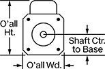 |  |
To improve positioning accuracy, these stepper motors have a built-in encoder that monitors the real-time speed and position of the shaft. It sends that data to a controller (not included), which adjusts or stops the shaft if it isn’t in the right place. This makes them useful when relative positioning is critical, such as when coordinating motion between two motors. Stepper motors are good for precise, repetitive movements. Similar to the hands of a clock, their shaft turns in small, equal increments for smooth motion. When the shaft stops, it holds its position even when a counteracting force is applied to the load. All are bipolar hybrid stepper motors, so the current can flow in both directions. This helps them deliver higher torque, precision, and efficiency than unipolar stepper motors.
All motors require a controller and drive (not included).
2 Shafts—When relative positioning is critical, such as coordinating motion in a multi-axis system, choose a motor with two shafts and mount an encoder (not included) on one of them. The encoder monitors the position of the shaft and reports back to the controller.
Maximum Holding Torque—Holding torque is the force needed to move the shaft out of position when it is stationary. When the shaft is in motion, torque generally decreases as speed increases. Use a torque-speed curve to confirm which motor will work for your application. Click on a part number and select “Product Detail” to view the curve for a motor.
Full Step Increment—Full step increment is the rotation of the shaft from one position to the next. A smaller full step increment means the rotor has more teeth, producing smoother and more precise motion. 1.8° is considered standard.
Overall | Shaft | Temp. Range, ° F | ||||||||||||||||||||
|---|---|---|---|---|---|---|---|---|---|---|---|---|---|---|---|---|---|---|---|---|---|---|
Max. Holding Torque, in·ozf | Max. Rotation Speed, rpm | Max. Current per Phase, amp | Voltage, V DC | Full Step Increment | Stepper Motor Polarity | Encoder Positioning Type | No. of Counts per Rev. | No. of Wire Leads | Lg. | Wd. | Ht. | Dia. | Lg. | Ctr.-to-Base Lg. | Type | No. of Shafts | Min. | Max. | Each | |||
Square Body | ||||||||||||||||||||||
NEMA 17 Frame Size | ||||||||||||||||||||||
| 26.9 | 1,500 | 0.67 | 5 | 1.8° | Bipolar | Incremental | 1,000 | 4 | 2.6" | 2.3" | 1.7" | 5 mm | 22 mm | 0.84" | D-Profile | 2 | 0 | 120 | 6627T361 | 0000000 | ||
| 39 | 900 | 0.62 | 5 | 1.8° | Bipolar | Incremental | 1,000 | 4 | 2.8" | 2.3" | 1.7" | 5 mm | 22 mm | 0.84" | Solid | 2 | 0 | 120 | 6627T371 | 000000 | ||
| 64 | 750 | 0.7 | 5 | 1.8° | Bipolar | Incremental | 1,000 | 4 | 3" | 2.3" | 1.7" | 5 mm | 22 mm | 0.84" | Solid | 2 | 0 | 120 | 6627T381 | 000000 | ||
| 70.8 | 3,000 | 2 | 5 | 1.8° | Bipolar | Incremental | 1,000 | 4 | 3.2" | 2.3" | 1.7" | 5 mm | 22 mm | 0.84" | D-Profile | 2 | 0 | 120 | 6627T391 | 000000 | ||
| 83.5 | 825 | 1.05 | 5 | 1.8° | Bipolar | Incremental | 1,000 | 4 | 3.5" | 2.3" | 1.7" | 5 mm | 22 mm | 0.84" | D-Profile | 2 | 0 | 120 | 6627T411 | 000000 | ||
| 124.6 | 1,400 | 2 | 5 | 1.8° | Bipolar | Incremental | 1,000 | 4 | 3.9" | 2.3" | 1.7" | 5 mm | 22 mm | 0.84" | D-Profile | 2 | 0 | 120 | 6627T421 | 000000 | ||
NEMA 23 Frame Size | ||||||||||||||||||||||
| 181 | 600 | 2.8 | 5 | 1.8° | Bipolar | Incremental | 1,000 | 4 | 3.7" | 2.6" | 2.3" | 1/4" | 3/4" | 1.13" | D-Profile | 2 | 0 | 120 | 6627T441 | 000000 | ||
| 237 | 525 | 4 | 5 | 1.8° | Bipolar | Incremental | 1,000 | 4 | 4.6" | 2.6" | 2.3" | 1/4" | 3/4" | 1.13" | D-Profile | 2 | 0 | 120 | 6627T451 | 000000 | ||
| 355 | 900 | 6 | 5 | 1.8° | Bipolar | Incremental | 1,000 | 4 | 4.9" | 2.6" | 2.3" | 1/4" | 3/4" | 1.13" | D-Profile | 2 | 0 | 120 | 6627T461 | 000000 | ||
| 467.3 | 300 | 2 | 5 | 1.8° | Bipolar | Incremental | 1,000 | 4 | 4.5" | 2.5" | 2.3" | 1/4" | 3/4" | 1.11" | D-Profile | 2 | 0 | 120 | 6627T471 | 000000 | ||
| 600.4 | 1,300 | 6.5 | 5 | 1.8° | Bipolar | Incremental | 1,000 | 4 | 4.9" | 2.6" | 2.3" | 1/4" | 3/4" | 1.13" | D-Profile | 2 | 0 | 120 | 6627T481 | 000000 | ||
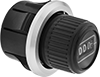
Harsh Environment Potentiometers
 |  |
Plastic Housing | Metal Housing |
Rated NEMA 13, these potentiometers protect against debris and splashing oil and coolant. Also known as variable output switches, they vary electrical flow to control speed, volume, and light intensity.
NEMA 4X Enclosure Rating—NEMA 4X rated potentiometers withstand weather, washdowns, and corrosion.
NEMA 6 Enclosure Rating—NEMA 6 potentiometers seal out water from temporary submersion as well as weather and washdowns.
Actuator | |||||||||||||||
|---|---|---|---|---|---|---|---|---|---|---|---|---|---|---|---|
Wattage @ Voltage | Max. Voltage | For Panel Cutout Dia. | Dp. Behind Panel | No. of Turns | Resolution | Dia. | Material | Wire Connection | Enclosure Rating | Certification | Choose a Maximum Resistance, kohm | Each | |||
Plastic Housing | |||||||||||||||
| 2 W @ 120V AC 2 W @ 24V DC | 500V AC/500V DC | 7/8", 22 mm | 2 1/4" | 1 | 10% | 1 1/8" | Plastic | Screw Terminal | NEMA 4X, NEMA 13, IP65 | UL Listed, C-UL Listed, CE Marked | 1, 2.5, 5, 10 | 7506T1 | 000000 | ||
| 2 W @ 120V AC 2 W @ 24V DC | 500V AC/500V DC | 1 3/16", 30 mm | 2 1/8" | 1 | 10% | 1 1/8" | Plastic | Screw Terminal | NEMA 4X, NEMA 13, IP65 | UL Listed, C-UL Listed, CE Marked | 1, 2.5, 5, 10 | 7506T21 | 000000 | ||
Metal Housing | |||||||||||||||
| 2 W @ 300V AC 2 W @ 300V DC | 300V AC/300V DC | 1 3/16", 30 mm | 1 15/16" | 1 | 5% | 1 1/8" | Plastic | Screw Terminal | NEMA 6, NEMA 13, IP65 | UL Listed, C-UL Listed, CSA Certified, CE Marked | 2.5, 5, 10 | 6787K52 | 000000 | ||
Precision Potentiometers
Push Button Actuator
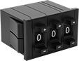 |  |
3 Digits | 4 Digits |
Potentiometers | Covers | |||||||||||||
|---|---|---|---|---|---|---|---|---|---|---|---|---|---|---|
For Panel Cutout | ||||||||||||||
Wattage @ Voltage | No. of Digits | Resolution | Ht. | Wd. | Dp. Behind Panel | Housing Material | Wire Connection | No. of Terminals | Choose a Maximum Resistance, kohm | Each | Each | |||
| 2 W @ 500V AC | 3 | 0.1% | 13/16" | 1 7/16" | 1 3/8" | Plastic | Tab | 3 | 1, 5, 10, 20, 50 | 7436K36 | 000000 | 7436K51 | 000000 | |
| 2 W @ 500V AC | 4 | 0.01% | 13/16" | 1 13/16" | 1 3/8" | Plastic | Tab | 3 | 10, 20 | 7436K116 | 00000 | ——— | 0 | |
Rotary Actuator
 |
Wattage @ Voltage | No. of Digits | Resolution | No. of Turns | For Panel Cutout Dia. | Dp. Behind Panel | Dia. | Housing Material | Wire Connection | No. of Terminals | Choose a Maximum Resistance, kohm | Each | ||
|---|---|---|---|---|---|---|---|---|---|---|---|---|---|
| 1.5 W @ 385V AC | 3 | 0.1% | 10 | 1" | 5/8" | 1 1/4" | Plastic | Tab | 3 | 1, 5, 10 | 7436K43 | 0000000 | |
| 1.5 W @ 385V AC | 3 | 0.1% | 10 | 10 mm | 1/2" | 7/8" | Plastic | Tab | 3 | 1, 5, 10 | 7436K112 | 000000 |
Programmable Potentiometers
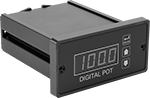 |
For quick, repeatable adjustments to electronic equipment, these potentiometers adjust and save electrical settings. They’re typically used to control speed, volume, or light intensity. For example, if a conveyor needs different speeds for different tasks, you can program each speed into them. Set the digital display to show the specific measurement unit for your application, such as motor rpm.
Install them in a standard 1/8 DIN panel cutout. They’re NEMA 4X rated to resist corrosion, washdowns, and weather.
For Panel Cutout | |||||||||||||||||
|---|---|---|---|---|---|---|---|---|---|---|---|---|---|---|---|---|---|
Input Voltage, V AC | Output Voltage, V DC | Input Freq., Hz | Digital Display Type | No. of Digits | Resolution | DIN Size | Ht. | Wd. | Dp. Behind Panel | Housing Material | Wire Connection | No. of Terminals | Mounting Fasteners Included | Enclosure Rating | Each | ||
| 85 to 250 | 0 to 24 | 50, 60 | LED | 4 | 0.1% | 1/8 | 1 3/4" | 3 5/8" | 4 5/8" | Aluminum | Screw Terminal | 12 | Yes | NEMA 4X | 8890N11 | 0000000 | |
Variable-Speed Foot Potentiometers
 |  |
Iron Housing | Iron Housing with Aluminum Guard |
When the pedal is pressed, the built-in potentiometer adjusts the resistance to vary the speed for motor drives. These switches can be wired to either increase or decrease the current when actuated. All are rated NEMA 4 and 13 for protection from washdowns and oil/coolant spraying.
Mounting | ||||||||||||||||
|---|---|---|---|---|---|---|---|---|---|---|---|---|---|---|---|---|
No. of Circuits Controlled | Switch Starting Position | Switch Action | Switch Designation | Switching Current @ Voltage | No. of Terminals | Quick-Disconnect Tab Wd. | Conduit Trade Size | Enclosure Rating | Fasteners Included | No. of | Hole Dia. | Choose a Maximum Resistance, kohm | Each | |||
Quick-Disconnect-Terminal Wire Connection | ||||||||||||||||
Iron Housing | ||||||||||||||||
| 1 | 1 Off or 1 On | Momentary | SPDT | 15 amp @ 125V AC/250V AC | 3 | 0.187" | 3/4 | IP56, NEMA 4, NEMA 13 | No | 3 | 0.31" | 1, 5, 10 | 6817K11 | 0000000 | ||
Iron Housing with Aluminum Guard | ||||||||||||||||
| 1 | 1 Off or 1 On | Momentary | SPDT | 15 amp @ 125V AC/250V AC | 3 | 0.187" | 3/4 | IP56, NEMA 4, NEMA 13 | No | 3 | 0.31" | 1, 5, 10 | 6817K31 | 000000 | ||
Linear Motion Potentiometers
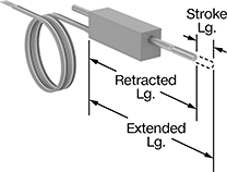 |
Pair these potentiometers with a controller to monitor the position of moving parts or send instructions to an electrical system. They have a rod that slides back and forth against an internal resistor, which increases or decreases the voltage flowing out to your controller. To monitor the position of a moving part, such as a robotic component, connect it to the rod. As the part moves, it pushes the rod back and forth, which allows the controller to observe and report the part’s exact position. To use these potentiometers as part of a controls system, connect them to a volume slider or other manual control. When you move the slider, the controller converts its position into instructions for electrical equipment, such as adjusting volume levels. These potentiometers are also called variable output switches.
Lg. | Rod | 5 kohm Maximum Resistance | 10 kohm Maximum Resistance | |||||||||||||
|---|---|---|---|---|---|---|---|---|---|---|---|---|---|---|---|---|
Stroke | Retracted | Extended | Wattage @ Voltage | Wd. | Ht. | Dia. | Thread Size | Material | Housing Material | Wire Connection | Enclosure Rating | Each | Each | |||
| 5/32" | 1.59" | 1.74" | 0.125 W @ 200V DC | 1/4" | 9/32" | 1/16" | 0-80 | 303 Stainless Steel | Plastic | Wire Leads | IP45 | 7625N11 | 000000 | 7625N12 | 000000 | |
| 1/4" | 1.59" | 1.84" | 0.125 W @ 200V DC | 1/4" | 9/32" | 1/16" | 0-80 | 303 Stainless Steel | Plastic | Wire Leads | IP45 | 7625N13 | 00000 | 7625N14 | 00000 | |
| 1/2" | 2.22" | 2.72" | 0.25 W @ 300V DC | 9/32" | 11/32" | 3/32" | 2-56 | 303 Stainless Steel | Plastic | Wire Leads | IP45 | 7625N15 | 00000 | 7625N16 | 00000 | |
