


Mounting Location Mounting Location |
|---|
|
Industry Designation Industry Designation |
|---|
Switch Starting Position Switch Starting Position |
|---|
Component Component |
|---|
|
|
Wire Connection Type Wire Connection Type |
|---|
|
DFARS (Defense Acquisition Regulations Supplement) DFARS (Defense AcquisitionRegulations Supplement) |
|---|
Switch Type Switch Type |
|---|
|
RoHS (Restriction of Hazardous Substances) RoHS (Restriction ofHazardous Substances) |
|---|
|
Choosing an Electrical Switch
More
Choosing a Proximity Switch
More
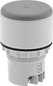
Two-Hand Safety Switches
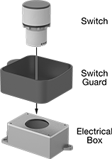
It takes two hands to activate these switches, minimizing the risk of accidental equipment start up. A complete system requires two switches, one safety relay, and two outlet boxes.
Switches meet OSHA requirements and ANSI standards for machine operator safety. They're rated IP64 for protection from splashing water.
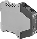
Safety relays control the two switches by sending an output signal when both switches are activated within 0.5 seconds of each other. Self-monitoring circuitry offers additional protection—if any part of the system fails, the entire system shuts down until repaired.
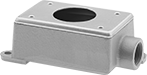
Outlet boxes have a drilled hole to fit the switch.
Switch guards protect switches against damage and accidental activation. Use one guard per switch.
![]() For technical drawings and 3-D models, click on a part number.
For technical drawings and 3-D models, click on a part number.
Actuator | |||||||||||
|---|---|---|---|---|---|---|---|---|---|---|---|
| Input Voltage | No. of Circuits Controlled | Switch Starting Position | Switch Action | No. of Terminals | Industry Designation | Material | Color | Switching Current @ Voltage | Dia. | Each | |
| 24V DC | 2 | 1 Off (Normally Open) and 1 On (Normally Closed) | Springs Back (Momentary) | 4 | DPST-1NO/1NC | Plastic | Gray | 1 A @ 250 V AC/90 V DC | 2 3/8" | 00000000 | 0000000 |
| 120V AC | 2 | 1 Off (Normally Open) and 1 On (Normally Closed) | Springs Back (Momentary) | 4 | DPST-1NO/1NC | Plastic | Gray | 1 A @ 250 V AC/90 V DC | 2 3/8" | 00000000 | 000000 |
| Input Voltage | No. of Circuits Controlled | Switch Starting Position | No. of Terminals | Industry Designation | Switching Current @ Voltage | For DIN Rail Ht., mm | Wire Connection Type | Each | |
| 24V AC/24V DC | 2 | 2 Off (Normally Open) | 4 | DPST-NO | 4 A @ 230 V AC, 2 A @ 24 V DC | 35 | Screw Terminals | 00000000 | 0000000 |
| 115V AC | 2 | 2 Off (Normally Open) | 4 | DPST-NO | 4 A @ 230 V AC, 2 A @ 24 V DC | 35 | Screw Terminals | 00000000 | 000000 |
Conduit | ||||||||
|---|---|---|---|---|---|---|---|---|
| No. of Connections | Trade Size | Ht. | Wd. | Dp. | Mounting Fasteners Included | Environmental Rating | Each | |
| 1 | 3/4 | 2 1/8" | 2 7/8" | 6" | Yes | IP64 | 00000000 | 0000000 |

| Ht. | Wd. | Dp. | Each | |
| 2" | 4 7/8" | 5 3/8" | 00000000 | 0000000 |
Light Beam Safety Barrier Switches
Immediately cut power to machinery by breaking the light beam between the two barriers. Light beams can travel up to 32 feet between the transmitter and receiver. For a complete system, combine a transmitter, receiver, safety relay, and connectors (sold separately). Switches will automatically produce PNP or NPN signal output based on the device they are connected to. To selectively allow material to pass through the sensing field, you can program the system to allow one or more beams to be broken without shutting off your machine.
Note: These switches cannot be used with a full-revolution clutch press or machine. Use only with machinery that can consistently and immediately stop anywhere in its cycle.
Use safety relays when connecting these barrier switches to emergency stop switches.
![]() For technical drawings and 3-D models, click on a part number.
For technical drawings and 3-D models, click on a part number.
| Input Voltage | No. of Circuits Controlled | Switching Current @ Voltage | Industry Designation | Wire Connection Type | Ht. | Wd. | Dp. | Features | For DIN Rail Ht., mm | Each | |
| 24V DC | 2 | 2 A @ 240 V AC, 1.5 A @ 24 V DC | DPST-NO | Terminal Block | 4.9" | 0.69" | 4.3" | Auxiliary PNP Output | 35 | 0000000 | 0000000 |
| 24V DC | 4 | 2 A @ 240 V AC, 1.5 A @ 24 V DC | 4PST-NO | Terminal Block | 4.9" | 0.89" | 4.3" | Auxiliary PNP Output | 35 | 0000000 | 000000 |
Machine-Guard Safety Screw Terminal Relays
The interlocked opposing contacts won't close at the same time, so these relays are suitable for safety applications such as machine guarding. The screw terminals are recessed to prevent accidental contact with live connections. Relays are built to International Electrotechnical Commission (IEC) dimensional standards.
Auxiliary contact (sold separately) allows you to add a signaling device or control another relay.

| Number of Terminals | Input Voltage | Control Current, mA | Switching Current @ 600V AC | Ht. | Wd. | Dp. | For DIN Rail Size, mm | Specifications Met | Each | |
4 Circuits Controlled with 2 Off (Normally Open) and 2 On (Normally Closed)—4PST-2NO/2NC | ||||||||||
|---|---|---|---|---|---|---|---|---|---|---|
| 10 | 24V AC | 125 | 10A | 2.3" | 1.7" | 2.2" | 35 | UL Listed, C-UL Listed | 00000000 | 000000 |
| 10 | 120V AC | 25 | 10A | 2.3" | 1.7" | 2.2" | 35 | UL Listed, C-UL Listed | 00000000 | 00000 |
| 10 | 240V AC | 12.5 | 10A | 2.3" | 1.7" | 2.2" | 35 | UL Listed, C-UL Listed | 00000000 | 00000 |
4 Circuits Controlled with 3 Off (Normally Open) and 1 On (Normally Closed)—4PST-3NO/1NC | ||||||||||
| 10 | 24V AC | 125 | 10A | 2.3" | 1.7" | 2.2" | 35 | UL Listed, C-UL Listed | 00000000 | 00000 |
| 10 | 120V AC | 25 | 10A | 2.3" | 1.7" | 2.2" | 35 | UL Listed, C-UL Listed | 00000000 | 00000 |
| 10 | 240V AC | 12.5 | 10A | 2.3" | 1.7" | 2.2" | 35 | UL Listed, C-UL Listed | 00000000 | 00000 |
| Number of Circuits Controlled | Switch Starting Position | Industry Designation | Mounting Location | Each | |
| 2 | 1 Off (Normally Open) and 1 On (Normally Closed) | DPST-1NO/1NC | Front | 00000000 | 000000 |