


Filter by
Flexibility
Shielding
Wire Finish
Current @ Temperature
Wire and Cable Use
DFARS Specialty Metals
Export Control Classification Number (ECCN)
REACH
Outer Jacket Material
Inner Insulation Material

About Wire and Cable
Compare wire vs. cable and choose the right option based on gauge, number of conductors, insulation, and current rating.
Outdoor Lead Wire
2,000V AC
AWG | Current @ Temp. | OD | Max. Temp., ° F | Outer Jacket Material | Inner Insulation Material | Outer Jacket Color | Cable Designation | Certification | Flammability Rating | 10 ft. Long | 25 ft. Long | 50 ft. Long | 100 ft. Long | |||
|---|---|---|---|---|---|---|---|---|---|---|---|---|---|---|---|---|
Stranded Wire | ||||||||||||||||
| 12 | Not Rated | 0.21" | 190 | CPE | EPDM | Black | DLO, RHW-2 | MSHA Accepted, UL Listed | UL 2556 FT4 | 6584T24 | 000000 | 000000 | 000000 | 000000 | ||
| 10 | Not Rated | 0.27" | 190 | CPE | EPDM | Black | DLO, RHW-2 | MSHA Accepted, UL Listed | UL 2556 FT4 | 6584T25 | 00000 | 00000 | 00000 | 000000 | ||
| 8 | 55 amp @ 86° F | 0.33" | 190 | CPE | EPDM | Black | DLO, RHW-2 | CSA Certified, MSHA Accepted, UL Listed | UL 2556 FT4 | 6584T26 | 00000 | 00000 | 000000 | 000000 | ||
| 6 | 75 amp @ 86° F | 0.37" | 190 | CPE | EPDM | Black | DLO, RHW-2 | CSA Certified, MSHA Accepted, UL Listed | UL 2556 FT4 | 6584T27 | 00000 | 00000 | 000000 | 000000 | ||
| 4 | 95 amp @ 86° F | 0.44" | 190 | CPE | EPDM | Black | DLO, RHW-2 | CSA Certified, MSHA Accepted, UL Listed | UL 2556 FT4 | 6584T28 | 00000 | 000000 | 000000 | 000000 | ||
| 2 | 130 amp @ 86° F | 0.5" | 190 | CPE | EPDM | Black | DLO, RHW-2 | MSHA Accepted, UL Listed | UL 2556 FT4 | 6584T29 | 00000 | 000000 | 000000 | 000000 | ||
| 1/0 | 170 amp @ 86° F | 0.65" | 190 | CPE | EPDM | Black | DLO, RHW-2 | CSA Certified, MSHA Accepted, UL Listed | UL 2556 FT4 | 6584T31 | 000000 | 000000 | 000000 | 000000 | ||
| 2/0 | 195 amp @ 86° F | 0.69" | 190 | CPE | EPDM | Black | DLO, RHW-2 | MSHA Accepted, UL Listed | UL 2556 FT4 | 6584T32 | 000000 | 000000 | 000000 | 000000 | ||
| 4/0 | 260 amp @ 86° F | 0.82" | 190 | CPE | EPDM | Black | DLO, RHW-2 | MSHA Accepted, UL Listed | UL 2556 FT4 | 6584T33 | 000000 | 000000 | 000000 | 00000000 | ||
Servomotor Continuous-Flex Cable
Power Wire—Stranded
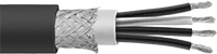 |  |
Double Shielded |
Cable with power wires sends electricity to run a servomotor.
Double Shielded—Double shielded cable has a layer of braid and foil shielding for better protection against signal interference than braid alone. Use it in environments with high signal distortion, such as near transformers, generators, and heavy duty motors.
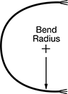
Bend Radius—Bend radius is the point to which the cable will bend without being damaged. It is measured from the center of the bend to the edge of the cable. The smaller the measurement, the tighter the bend.
Per Ft. | ||||||||||||||||||
|---|---|---|---|---|---|---|---|---|---|---|---|---|---|---|---|---|---|---|
No. of Wires | AWG | Cable AWG | Current @ Temp. | OD | Bend Radius | Outer Jacket Material | Outer Jacket Color | Inner Insulation Material | Inner Insulation Color | Temp. Range, ° F | Certification | Flammability Rating | Choose a Length, ft. | 1-49 | 50-Up | |||
Double Shielded—1,000V AC | ||||||||||||||||||
| 4 | 14 | 14/4 | 15 amp @ 86° F | 0.42" | 3.15" | Polyurethane Rubber | Orange | Polypropylene | Black, Green/Yellow | -40 to 175 | UL Recognized Component, CSA Certified | UL 2556 VW-1 | 5, 10, 20, 30, 50 | 8815T11 | 00000 | 00000 | ||
| 4 | 12 | 12/4 | 20 amp @ 86° F | 0.47" | 3.53" | Polyurethane Rubber | Orange | Polypropylene | Black, Green/Yellow | -40 to 175 | UL Recognized Component, CSA Certified | UL 2556 VW-1 | 5, 10, 20, 30, 50 | 8815T13 | 00000 | 00000 | ||
| 4 | 10 | 10/4 | 30 amp @ 86° F | 0.57" | 4.28" | Polyurethane Rubber | Orange | Polypropylene | Black, Green/Yellow | -40 to 175 | UL Recognized Component, CSA Certified | UL 2556 VW-1 | 5, 10, 20, 30, 50 | 8815T14 | 00000 | 00000 | ||
Control Wire—Stranded
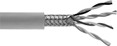 | |
Shielded |
Cable with control wires is also known as feedback cable. It sends and receives signals between a servomotor and a PLC.
Shielded—Shielded cable has a layer of braid that blocks signal interference from nearby equipment and devices.
Bend Radius—Bend radius is the point to which the cable will bend without being damaged. It is measured from the center of the bend to the edge of the cable. The smaller the measurement, the tighter the bend.
No. of Wires | AWG | Cable AWG | Current @ Temp. | OD | Bend Radius | Outer Jacket Material | Outer Jacket Color | Inner Insulation Material | Inner Insulation Color | Temp. Range, ° F | Certification | Flammability Rating | 5 ft. Long | 10 ft. Long | 20 ft. Long | 30 ft. Long | 50 ft. Long | |||
|---|---|---|---|---|---|---|---|---|---|---|---|---|---|---|---|---|---|---|---|---|
Shielded—30V AC/ 45V DC | ||||||||||||||||||||
| 8 | 26 | 26/8 | 0.7 amp @ 86° F | 0.25" | 2.17" | Polyurethane Rubber | Green | Polypropylene | Black, Blue, Brown, Green, Orange, Purple, Red, Yellow | -40 to 175 | UL Recognized Component | UL 2556 VW-1 | 8815T21 | 000000 | 000000 | 0000000 | 0000000 | 0000000 | ||
| 8 | 24 | 24/8 | 1.4 amp @ 86° F | 0.29" | 1.87" | Polyurethane Rubber | Green | Polypropylene | Blue, Brown, Gray, Green, Pink, Red, White, Yellow | -40 to 175 | UL Recognized Component | UL 2556 VW-1 | 8815T22 | 00000 | 00000 | 000000 | 000000 | 000000 | ||
Power and Control Wire—Stranded
| |
Double Shielded |
Cable with power and control wires sends data such as positioning information from a servomotor to a controller. It has four power wires and two pairs of control wires.
Double Shielded—Double shielded cable has a layer of braid and foil shielding for better protection against signal interference than braid alone. Use it in environments with high signal distortion, such as near transformers, generators, and heavy duty motors.
Bend Radius—Bend radius is the point to which the cable will bend without being damaged. It is measured from the center of the bend to the edge of the cable. The smaller the measurement, the tighter the bend.
Power Wire | Control Wire | Per Ft. | |||||||||||||||||||||||
|---|---|---|---|---|---|---|---|---|---|---|---|---|---|---|---|---|---|---|---|---|---|---|---|---|---|
No. of Wires | No. of Wires | AWG | Cable AWG | No. of Wires | AWG | Cable AWG | No. of Wires | AWG | Cable AWG | Current @ Temp. | OD | Bend Radius | Outer Jacket Material | Outer Jacket Color | Inner Insulation Material | Inner Insulation Color | Temp. Range, ° F | Certification | Flammability Rating | Choose a Length, ft. | 1-49 | 50-Up | |||
Double Shielded—1,000V AC | |||||||||||||||||||||||||
| 8 | 4 | 14 | 14/4 | 4 | 18 | 18/4 | — | — | — | 15 amp @ 86° F | 0.57" | 4.28" | Polyurethane Rubber | Orange | Polypropylene | Black, Green/Yellow | -40 to 175 | UL Recognized Component, CSA Certified | UL 2556 VW-1 | 5, 10, 20, 30, 50 | 8815T16 | 000000 | 000000 | ||
| 8 | 4 | 12 | 12/4 | 2 | 18 | 18/2 | 2 | 16 | 16/2 | 20 amp @ 86° F | 0.64" | 4.8" | Polyurethane Rubber | Orange | Polypropylene | Black, Green/Yellow | -40 to 175 | UL Recognized Component, CSA Certified | UL 2556 VW-1 | 5, 10, 20, 30, 50 | 8815T17 | 00000 | 00000 | ||
| 8 | 4 | 10 | 10/4 | 2 | 18 | 18/2 | 2 | 16 | 16/2 | 30 amp @ 86° F | 0.71" | 5.33" | Polyurethane Rubber | Orange | Polypropylene | Black, Green/Yellow | -40 to 175 | UL Recognized Component, CSA Certified | UL 2556 VW-1 | 5, 10, 20, 30, 50 | 8815T18 | 00000 | 00000 | ||
