


System of Measurement System of Measurement |
|---|
|
Thread Size Thread Size | Show |
|---|
Thread Size Thread Size | Hide |
|---|
Material Material |
|---|
|
Mechanical Finish Mechanical Finish |
|---|
|
Edge Type Edge Type |
|---|
| Chamfered | |
Threading Threading |
|---|
|
For Motion Type For Motion Type |
|---|
 | Linear |
RoHS (Restriction of Hazardous Substances) RoHS (Restriction ofHazardous Substances) |
|---|
|
REACH (Registration, Evaluation, Authorization and Restriction of Chemicals) REACH (Registration,Evaluation, Authorization and Restriction of Chemicals) |
|---|
|
DFARS (Defense Acquisition Regulations Supplement) DFARS (Defense AcquisitionRegulations Supplement) |
|---|
Hardness Rating Hardness Rating |
|---|
|
Thread Pitch Thread Pitch |
|---|
|
Surface Smoothness Surface Smoothness |
|---|
|
Yield Strength Yield Strength |
|---|
|
Surface Yield Strength Surface Yield Strength |
|---|
|
Heat Treatment Heat Treatment |
|---|
|
Head Type Head Type |
|---|
| Tapped | |
About Shafts
More
About Threaded Studs and Rods
More
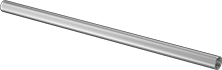
Tapped Linear Motion Shafts
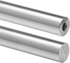
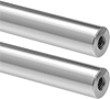
Internal threads allow you to mount these shafts onto threaded studs and fasteners, no shaft supports needed. Smooth, hard, and wear resistant, linear motion shafts work with linear bearings to reduce friction in manual and automated systems, such as those found in packing, machine tool, and material handling operations. The smooth surface reduces friction and wear on the bearing—the lower the microinch value a shaft has, the smoother its finish and the less friction it will create. Shafts are case-hardened to increase hardness and wear resistance on the surface of the shaft while allowing the center to remain soft for absorbing stresses caused by shifting loads. The edges are chamfered to remove sharp corners, reducing damage to bearings, housings, and other components during installation. All are turned, ground, and polished to tight diameter and straightness tolerances.
52100 alloy steel shafts are good for high-load applications. They are, however, more difficult to machine than carbon steel shafts.
440C stainless steel shafts are more corrosion resistant than steel shafts but can be more difficult to machine.
![]() For technical drawings and 3-D models, click on a part number.
For technical drawings and 3-D models, click on a part number.

Thread | |||||||||
|---|---|---|---|---|---|---|---|---|---|
| Lg. | Size | Lg. | Straightness Tolerance | Surface Smoothness, microinch | Edge Type | Heat Treatment | Yield Strength, psi | Each | |
Metric—52100 Alloy Steel (Rockwell C60) | |||||||||
6mm Dia. | |||||||||
| 50mm | M3 | 6mm | 0.050 mm per 300 mm | 16 | Chamfered | Case Hardened | 57,000 | 00000000 | 000000 |
| 100mm | M3 | 6mm | 0.050 mm per 300 mm | 16 | Chamfered | Case Hardened | 57,000 | 00000000 | 00000 |
| 150mm | M3 | 6mm | 0.050 mm per 300 mm | 16 | Chamfered | Case Hardened | 57,000 | 00000000 | 00000 |
| 300mm | M3 | 6mm | 0.050 mm per 300 mm | 16 | Chamfered | Case Hardened | 57,000 | 00000000 | 00000 |
Metric—440C Stainless Steel (Rockwell C56) | |||||||||
6mm Dia. | |||||||||
| 50mm | M3 | 6mm | 0.050 mm per 300 mm | 16 | Chamfered | Case Hardened | 14,000 | 00000000 | 00000 |
| 300mm | M3 | 6mm | 0.050 mm per 300 mm | 16 | Chamfered | Case Hardened | 14,000 | 00000000 | 000000 |
Thread | |||||||||
|---|---|---|---|---|---|---|---|---|---|
| Lg. | Size | Lg. | Straightness Tolerance | Surface Smoothness, microinch | Edge Type | Heat Treatment | Yield Strength, psi | Each | |
Metric—52100 Alloy Steel (Rockwell C60) | |||||||||
6mm Dia. | |||||||||
| 50mm | M3 | 6mm | 0.050 mm per 300 mm | 16 | Chamfered | Case Hardened | 57,000 | 00000000 | 000000 |
| 100mm | M3 | 6mm | 0.050 mm per 300 mm | 16 | Chamfered | Case Hardened | 57,000 | 00000000 | 00000 |
| 150mm | M3 | 6mm | 0.050 mm per 300 mm | 16 | Chamfered | Case Hardened | 57,000 | 00000000 | 00000 |
| 200mm | M3 | 6mm | 0.050 mm per 300 mm | 16 | Chamfered | Case Hardened | 57,000 | 00000000 | 00000 |
Metric—440C Stainless Steel (Rockwell C56) | |||||||||
6mm Dia. | |||||||||
| 50mm | M3 | 6mm | 0.050 mm per 300 mm | 16 | Chamfered | Case Hardened | 14,000 | 00000000 | 00000 |
| 150mm | M3 | 6mm | 0.050 mm per 300 mm | 16 | Chamfered | Case Hardened | 14,000 | 00000000 | 00000 |
Flat-Vent Pull-Out Dowel Pins
The flat side of these pins relieves trapped air, making them easier to insert and remove from blind holes. One end is tapped and the other is chamfered for easy insertion. To remove, thread a screw or tool into the tapped hole, then pull them out. Use them as pivots, hinges, shafts, jigs, and fixtures to locate or hold parts. Pins are precision ground for accurate alignment. Breaking strength is measured as double shear, which is the force required to break a pin into three pieces.
Metric pins meet DIN standards.
![]() For technical drawings and 3-D models, click on a part number.
For technical drawings and 3-D models, click on a part number.
Thread | ||||||||
|---|---|---|---|---|---|---|---|---|
| Lg., mm | Dia. Tolerance, mm | Size | Pitch, mm | Min. Hardness | Breaking Strength, lbs. | Specifications Met | Each | |
4 mm Dia. | ||||||||
| 16 | 0.004 to 0.015 | M3 | 0.5 | Rockwell C18 | 101,000 | DIN 7979C-m6 | 000000000 | 00000 |
| 20 | 0.004 to 0.015 | M3 | 0.5 | Rockwell C18 | 101,000 | DIN 7979C-m6 | 000000000 | 0000 |
5 mm Dia. | ||||||||
| 10 | 0.004 to 0.015 | M3 | 0.5 | Rockwell C18 | 101,000 | DIN 7979C-m6 | 000000000 | 0000 |
| 24 | 0.004 to 0.015 | M3 | 0.5 | Rockwell C18 | 101,000 | DIN 7979C-m6 | 000000000 | 0000 |
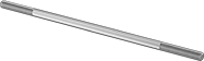
Metric Low-Strength Steel Threaded Rods
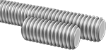
These threaded rods are about half the strength of medium-strength steel threaded rods for light duty hanging, mounting, and fastening.
Zinc-plated steel threaded rods are corrosion resistant in wet environments.
![]() For technical drawings and 3-D models, click on a part number.
For technical drawings and 3-D models, click on a part number.
| Lg. | Thread Pitch, mm | Tensile Strength, psi | Hardness | Specifications Met | Pkg. Qty. | Pkg. | |
Steel | |||||||
|---|---|---|---|---|---|---|---|
M3 | |||||||
| 1 m | 0.5 | 50,000 | Rockwell B49 | __ | 1 | 000000000 | 00000 |
Zinc-Plated Steel | |||||||
M3 | |||||||
| 12 mm | 0.5 | 50,000 | Rockwell B49 | DIN 976 | 10 | 000000000 | 0000 |
| 25 mm | 0.5 | 50,000 | Rockwell B49 | DIN 976 | 10 | 000000000 | 0000 |
| 50 mm | 0.5 | 50,000 | Rockwell B49 | DIN 976 | 5 | 000000000 | 0000 |
| 300 mm | 0.5 | 50,000 | Rockwell B49 | DIN 976 | 1 | 000000000 | 0000 |
| 1 m | 0.5 | 50,000 | Rockwell B49 | __ | 1 | 000000000 | 00000 |
Metric 18-8 Stainless Steel Threaded Rods
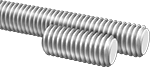
These 18-8 stainless steel threaded rods have good chemical resistance and may be mildly magnetic.
![]() For technical drawings and 3-D models, click on a part number.
For technical drawings and 3-D models, click on a part number.
| Lg. | Thread Pitch, mm | Tensile Strength, psi | Hardness | Specifications Met | Pkg. Qty. | Pkg. | |
18-8 Stainless Steel | |||||||
|---|---|---|---|---|---|---|---|
M3 | |||||||
| 12 mm | 0.5 | 70,000 | Not Rated | DIN 976 | 10 | 000000000 | 000000 |
| 16 mm | 0.5 | 70,000 | Not Rated | DIN 976 | 10 | 000000000 | 00000 |
| 20 mm | 0.5 | 70,000 | Not Rated | DIN 976 | 10 | 000000000 | 00000 |
| 25 mm | 0.5 | 70,000 | Not Rated | DIN 976 | 10 | 000000000 | 00000 |
| 300 mm | 0.5 | 70,000 | Not Rated | DIN 976 | 1 | 000000000 | 0000 |
| 500 mm | 0.5 | 70,000 | Not Rated | DIN 976 | 1 | 000000000 | 0000 |
| 1 m | 0.5 | 70,000 | Not Rated | DIN 976 | 1 | 000000000 | 0000 |
| 2 m | 0.5 | 70,000 | Not Rated | DIN 976 | 1 | 000000000 | 00000 |
Metric Super-Corrosion-Resistant 316 Stainless Steel Threaded Rods
These 316 stainless steel threaded rods are more corrosion resistant than 18-8 and 410 stainless steel threaded rods and have excellent resistance to chemicals and salt water. They may be mildly magnetic. All meet DIN 976 specifications for dimensional standards.
![]() For technical drawings and 3-D models, click on a part number.
For technical drawings and 3-D models, click on a part number.
| Lg. | Thread Pitch, mm | Tensile Strength, psi | Hardness | Specifications Met | Pkg. Qty. | Pkg. | |
316 Stainless Steel | |||||||
|---|---|---|---|---|---|---|---|
M3 | |||||||
| 12 mm | 0.5 | 70,000 | Not Rated | DIN 976 | 5 | 000000000 | 000000 |
| 25 mm | 0.5 | 70,000 | Not Rated | DIN 976 | 5 | 000000000 | 0000 |
| 300 mm | 0.5 | 70,000 | Not Rated | DIN 976 | 1 | 000000000 | 0000 |
| 500 mm | 0.5 | 70,000 | Not Rated | DIN 976 | 1 | 000000000 | 0000 |
| 1 m | 0.5 | 70,000 | Not Rated | DIN 976 | 1 | 000000000 | 00000 |
| 2 m | 0.5 | 70,000 | Not Rated | DIN 976 | 1 | 000000000 | 00000 |
Metric Brass Threaded Rods
These brass threaded rods are corrosion resistant in wet environments, electrically conductive, and nonmagnetic.
![]() For technical drawings and 3-D models, click on a part number.
For technical drawings and 3-D models, click on a part number.
| Lg., m | Thread Pitch, mm | Tensile Strength, psi | Hardness | Specifications Met | Each | |
Brass | ||||||
|---|---|---|---|---|---|---|
M3 | ||||||
| 1 | 0.5 | 50,000 | Rockwell B55 | DIN 976 | 000000000 | 000000 |
Metric Partially Threaded Studs
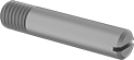
Screw the threaded end of these metric studs into a tapped hole and use the unthreaded end as a pivot point, hinge, shaft, or locator pin. All can be installed and adjusted by hand or with a slotted screwdriver. These studs are steel for strength and wear resistance. They’re best for dry environments, since moisture will cause them to rust. All meet ISO 2342 (formerly DIN 427), an international standard for fastener dimensions.
![]() For technical drawings and 3-D models, click on a part number.
For technical drawings and 3-D models, click on a part number.
Shaft | |||||||||||
|---|---|---|---|---|---|---|---|---|---|---|---|
| Lg., mm | Thread Lg., mm | Lg., mm | Dia., mm | Dia. Tolerance, mm | Tensile Strength | Hardness | Drive Style | Specifications Met | Pkg. Qty. | Pkg. | |
Steel | |||||||||||
M3 × 0.5 mm | |||||||||||
| 6 | 3.6 | 2.4 | 3 | -0.14 to 0 | Not Rated | Rockwell B75 | Slotted | DIN 427, ISO 2342 | 25 | 000000000 | 00000 |
| 10 | 3.6 | 6.4 | 3 | -0.14 to 0 | Not Rated | Rockwell B75 | Slotted | DIN 427, ISO 2342 | 25 | 000000000 | 00000 |
| 12 | 3.6 | 8.4 | 3 | -0.14 to 0 | Not Rated | Rockwell B75 | Slotted | DIN 427, ISO 2342 | 25 | 000000000 | 00000 |
Steel Press-Fit Studs
These steel studs are zinc plated to resist corrosion in wet environments. Press them into a drilled or punched hole with an arbor press or similar pressure tool. Also known as self-clinching studs, ribs under the head hold the stud firmly in place. Length listed is overall length.
![]() For technical drawings and 3-D models, click on a part number.
For technical drawings and 3-D models, click on a part number.
| Lg., mm | Thread Pitch, mm | PEM® Part Number | Thread Lg., mm | Drill Bit Size | For Min. Material Thick., mm | For Min. Lg. Between Hole Center and Sheet Edge, mm | For Hole Dia., mm | Hole Size Tolerance, mm | Base Dia., mm | Tensile Strength | Hardness | Pkg. Qty. | Pkg. | |
Metric Zinc-Plated Steel | ||||||||||||||
|---|---|---|---|---|---|---|---|---|---|---|---|---|---|---|
M3 | ||||||||||||||
| 6 | 0.5 | FH-M3-6 | 4 | 3.0 mm | 1.000 | 5.5 | 3 | 0.000 to 0.08 | 5 | Not Rated | Not Rated | 50 | 000000000 | 000000 |
| 8 | 0.5 | FH-M3-8 | 6 | 3.0 mm | 1.000 | 5.5 | 3 | 0.000 to 0.08 | 5 | Not Rated | Not Rated | 50 | 000000000 | 00000 |
| 10 | 0.5 | FH-M3-10 | 8 | 3.0 mm | 1.000 | 5.5 | 3 | 0.000 to 0.08 | 5 | Not Rated | Not Rated | 50 | 000000000 | 00000 |
| 12 | 0.5 | FH-M3-12 | 10 | 3.0 mm | 1.000 | 5.5 | 3 | 0.000 to 0.08 | 5 | Not Rated | Not Rated | 50 | 000000000 | 00000 |
| 15 | 0.5 | FH-M3-15 | 13 | 3.0 mm | 1.000 | 5.5 | 3 | 0.000 to 0.08 | 5 | Not Rated | Not Rated | 50 | 000000000 | 00000 |
| 18 | 0.5 | FH-M3-18 | 16 | 3.0 mm | 1.000 | 5.5 | 3 | 0.000 to 0.08 | 5 | Not Rated | Not Rated | 50 | 000000000 | 00000 |
| 20 | 0.5 | FH-M3-20 | 18 | 3.0 mm | 1.000 | 5.5 | 3 | 0.000 to 0.08 | 5 | Not Rated | Not Rated | 25 | 000000000 | 0000 |
| 25 | 0.5 | FH-M3-25 | 23 | 3.0 mm | 1.000 | 5.5 | 3 | 0.000 to 0.08 | 5 | Not Rated | Not Rated | 25 | 000000000 | 00000 |
Stainless Steel Press-Fit Studs
18-8 stainless steel studs have good chemical resistance and may be mildly magnetic. Press them into a drilled or punched hole with an arbor press or similar pressure tool. Also known as self-clinching studs, ribs under the head hold the stud firmly in place. Length listed is overall length.
![]() For technical drawings and 3-D models, click on a part number.
For technical drawings and 3-D models, click on a part number.
| Lg., mm | Thread Pitch, mm | PEM® Part Number | Thread Lg., mm | Drill Bit Size, mm | For Min. Material Thick., mm | For Min. Lg. Between Hole Center and Sheet Edge, mm | For Hole Dia., mm | Hole Size Tolerance, mm | Base Dia., mm | Tensile Strength | Hardness | Pkg. Qty. | Pkg. | |
Metric 18-8 Stainless Steel | ||||||||||||||
|---|---|---|---|---|---|---|---|---|---|---|---|---|---|---|
M3 | ||||||||||||||
| 6 | 0.5 | FHS-M3-6 | 4 | 3.0 | 1.000 | 5.5 | 3 | 0.000 to 0.08 | 4.2 | Not Rated | Not Rated | 25 | 000000000 | 00000 |
| 8 | 0.5 | FHS-M3-8 | 6 | 3.0 | 1.000 | 5.5 | 3 | 0.000 to 0.08 | 4.2 | Not Rated | Not Rated | 25 | 000000000 | 00000 |
| 10 | 0.5 | FHS-M3-10 | 8 | 3.0 | 1.000 | 5.5 | 3 | 0.000 to 0.08 | 4.2 | Not Rated | Not Rated | 50 | 000000000 | 00000 |
| 12 | 0.5 | FHS-M3-12 | 10 | 3.0 | 1.000 | 5.5 | 3 | 0.000 to 0.08 | 4.2 | Not Rated | Not Rated | 25 | 000000000 | 0000 |
| 15 | 0.5 | FHS-M3-15 | 13 | 3.0 | 1.000 | 5.5 | 3 | 0.000 to 0.08 | 4.2 | Not Rated | Not Rated | 25 | 000000000 | 0000 |
| 18 | 0.5 | FHS-M3-18 | 16 | 3.0 | 1.000 | 5.5 | 3 | 0.000 to 0.08 | 4.2 | Not Rated | Not Rated | 25 | 000000000 | 00000 |
| 20 | 0.5 | FHS-M3-20 | 18 | 3.0 | 1.000 | 5.5 | 3 | 0.000 to 0.08 | 4.2 | Not Rated | Not Rated | 10 | 000000000 | 0000 |
| 25 | 0.5 | FHS-M3-25 | 23 | 3.0 | 1.000 | 5.5 | 3 | 0.000 to 0.08 | 4.2 | Not Rated | Not Rated | 10 | 000000000 | 0000 |
Connecting Rods
Designed for use with right-hand threaded rod ends, these rods have right-hand threads on both ends. Use them for remote valve operators, throttle controllers, shifting mechanisms, and virtually any push/pull assembly.
Carbon steel rods without a plating are best for dry environments, since moisture will cause them to rust.
Aluminum rods are lightweight and corrosion resistant in wet environments.
18-8 stainless steel rods have good chemical resistance.
![]() For technical drawings and 3-D models, click on a part number.
For technical drawings and 3-D models, click on a part number.
Internally Threaded Connecting Rods
Designed for use with right-hand threaded rod ends, these rods have right-hand threads on both ends. Use them for remote valve operators, throttle controllers, shifting mechanisms, and virtually any push/pull assembly.
Carbon steel rods without a plating are best for dry environments, since moisture will cause them to rust.
Aluminum rods are lightweight and corrosion resistant in wet environments.
18-8 stainless steel rods have good chemical resistance.
![]() For technical drawings and 3-D models, click on a part number.
For technical drawings and 3-D models, click on a part number.