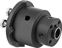
Friction Torque Limiters

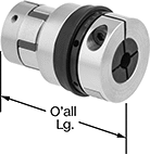
Use friction to prevent torque overload, control tension, and brake. These torque limiters slip when there’s too much torque while still transmitting the set torque. For example, they could be used in a machine that tightens a bottle cap to a certain torque without overtightening and breaking the bottle. Because they rely on friction, exposing them to moisture, oil, or lubricants can affect their performance. They have an adjustment ring, so you can set the torque limit by hand without removing them from your shaft. Fasten them to your shaft by tightening the set screws, which bite into the shaft to hold it.
Shaft-to-shaft torque limiters also act as a shaft coupling, allowing you to regulate torque transmission between two shafts.
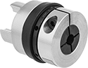
Through-shaft torque limiters regulate torque transmission between an input shaft and a mounted component, such as a pulley, sprocket, or gear.
Torque, in.-lbs | Keyway | ||||||||||
|---|---|---|---|---|---|---|---|---|---|---|---|
| For Shaft Dia. | Min. | Max. | Max. Speed, rpm | OD | Overall Lg. | Wd. | Dp. | Drive Direction | Mounting Hole Thread Size | Each | |
Shaft-to-Shaft | |||||||||||
For Round Shafts | |||||||||||
| 1/4" | 1.6 | 16 | 50 | 1" | 1 1/2" | __ | __ | Clockwise and Counterclockwise | __ | 9132K11 | 0000000 |
| 3/8" | 1.6 | 16 | 50 | 1" | 1 1/2" | __ | __ | Clockwise and Counterclockwise | __ | 9132K13 | 000000 |
| 3/8" | 2.5 | 25 | 50 | 1 3/8" | 2 1/2" | __ | __ | Clockwise and Counterclockwise | __ | 9132K15 | 000000 |
| 1/2" | 2.5 | 25 | 50 | 1 3/8" | 2 1/2" | __ | __ | Clockwise and Counterclockwise | __ | 9132K17 | 000000 |
| 1/2" | 5 | 50 | 50 | 1 5/8" | 2 1/2" | __ | __ | Clockwise and Counterclockwise | __ | 9132K19 | 000000 |
| 1/2" | 7.5 | 75 | 50 | 2 1/4" | 2 1/2" | __ | __ | Clockwise and Counterclockwise | __ | 9132K23 | 000000 |
| 5/8" | 5 | 50 | 50 | 1 5/8" | 2 1/2" | __ | __ | Clockwise and Counterclockwise | __ | 9132K21 | 000000 |
| 5/8" | 7.5 | 75 | 50 | 2 1/4" | 2 1/2" | __ | __ | Clockwise and Counterclockwise | __ | 9132K25 | 000000 |
For Keyed Shafts | |||||||||||
| 1/4" | 1.6 | 16 | 50 | 1" | 1 1/2" | 1/16" | 1/32" | Clockwise and Counterclockwise | __ | 9132K51 | 000000 |
| 3/8" | 2.5 | 25 | 50 | 1 3/8" | 2 1/2" | 3/32" | 3/64" | Clockwise and Counterclockwise | __ | 9132K52 | 000000 |
| 1/2" | 5 | 50 | 50 | 1 5/8" | 2 1/2" | 1/8" | 1/16" | Clockwise and Counterclockwise | __ | 9132K54 | 000000 |
| 1/2" | 7.5 | 75 | 50 | 2 1/4" | 2 1/2" | 1/8" | 1/16" | Clockwise and Counterclockwise | __ | 9132K56 | 000000 |
Through Shaft | |||||||||||
For Round Shafts | |||||||||||
| 1/4" | 1.6 | 16 | 50 | 1" | 1 1/2" | __ | __ | Clockwise and Counterclockwise | 4-40 | 9132K31 | 000000 |
| 3/8" | 1.6 | 16 | 50 | 1" | 1 1/2" | __ | __ | Clockwise and Counterclockwise | 4-40 | 9132K32 | 000000 |
| 3/8" | 2.5 | 25 | 50 | 1 3/8" | 2 1/2" | __ | __ | Clockwise and Counterclockwise | 6-32 | 9132K33 | 000000 |
| 1/2" | 2.5 | 25 | 50 | 1 3/8" | 2 1/2" | __ | __ | Clockwise and Counterclockwise | 6-32 | 9132K34 | 000000 |
| 1/2" | 5 | 50 | 50 | 1 5/8" | 2 1/2" | __ | __ | Clockwise and Counterclockwise | 6-32 | 9132K35 | 000000 |
| 1/2" | 7.5 | 75 | 50 | 2 1/4" | 2 1/2" | __ | __ | Clockwise and Counterclockwise | 8-32 | 9132K37 | 000000 |
| 5/8" | 5 | 50 | 50 | 1 5/8" | 2 1/2" | __ | __ | Clockwise and Counterclockwise | 6-32 | 9132K36 | 000000 |
| 5/8" | 7.5 | 75 | 50 | 2 1/4" | 2 1/2" | __ | __ | Clockwise and Counterclockwise | 8-32 | 9132K38 | 000000 |
For Keyed Shafts | |||||||||||
| 1/2" | 5 | 50 | 50 | 1 5/8" | 2 1/2" | 1/8" | 1/16" | Clockwise and Counterclockwise | 6-32 | 9132K44 | 000000 |
| 1/2" | 7.5 | 75 | 50 | 2 1/4" | 2 1/2" | 1/8" | 1/16" | Clockwise and Counterclockwise | 8-32 | 9132K46 | 000000 |
Noncontact-Magnetic Torque Limiters
Using magnetic force instead of friction to transmit torque, these torque limiters won't wear when they slip. Because there's no wear, they give you accurate, repeatable action. Also known as hysteresis clutches, use them to brake, control tension, and prevent torque overload. They are designed to slip during a torque overload while still transmitting the set torque. For example, you can use them to maintain a constant tension while winding and unwinding wire. All are through-shaft torque limiters, so they regulate torque transmission between an input shaft and a mounted component, such as a pulley, sprocket, or gear. Twist the adjustment ring to set the torque limit, then lock the ring into place with the included set screw.
Through-shaft limiters with D-profile shaft let you mount a component directly on the shaft.

Torque, in.-lbs | Mounting Hole | ||||||||||
|---|---|---|---|---|---|---|---|---|---|---|---|
| Min. | Max. | Max. Speed, rpm | OD | Overall Lg. | Drive Direction | Shaft Mount Type | Thread Size | Thread Pitch, mm | For Shaft Dia. | Each | |
| 0.06 | 1.25 | 880 | 1 15/16" | 1 5/8" | Clockwise and Counterclockwise | Set Screw | M4 | 0.7 | 1/4" | 7220K3 | 0000000 |
| 0.18 | 5 | 300 | 2 3/4" | 2 7/16" | Clockwise and Counterclockwise | Set Screw | M4 | 0.7 | 3/8" | 7220K4 | 000000 |
| 0.5 | 10.6 | 220 | 3 5/16" | 2 1/2" | Clockwise and Counterclockwise | Set Screw | M5 | 0.8 | 7220K5 | 000000 | |
| 1 | 25 | 250 | 4 11/16" | 3 1/8" | Clockwise and Counterclockwise | Set Screw | M5 | 0.8 | 7220K6 | 000000 | |
| 2 | 50 | 200 | 5 1/4" | 3 1/8" | Clockwise and Counterclockwise | Set Screw | M5 | 0.8 | 7220K7 | 000000 | |
| 3 | 70 | 200 | 6 5/16" | 4 1/8" | Clockwise and Counterclockwise | Set Screw | 1/4"-20 | __ | 7220K8 | 00000000 | |

Torque, in.-lbs | Mounting Hole | |||||||||
|---|---|---|---|---|---|---|---|---|---|---|
| Min. | Max. | Max. Speed, rpm | OD | Overall Lg. | Drive Direction | Thread Size | Thread Pitch, mm | Shaft Dia. | Each | |
| 0.01 | 0.06 | 2,000 | 1" | 1 3/8" | Clockwise and Counterclockwise | M3 | 0.5 | 3/16" | 7220K21 | 0000000 |
| 0.01 | 0.13 | 1,500 | 1" | 1 3/8" | Clockwise and Counterclockwise | M3 | 0.5 | 3/16" | 7220K22 | 000000 |
| 0.03 | 0.44 | 1,050 | 1 7/16" | 1 3/4" | Clockwise and Counterclockwise | M3 | 0.5 | 5/16" | 7220K23 | 000000 |
Overload-Protection Spring-Loaded Torque Limiters
Protect your machinery if there is a jam, emergency stop, or other overload by cutting off torque between shafts when a maximum torque is reached. These torque limiters automatically resume transmitting torque once it drops below the set maximum. They should not be used in applications that frequently exceed the maximum torque. Since they come factory-set to a maximum torque, there’s no adjustment required and no risk of unintended changes to the torque setting.
They act as a flexible shaft coupling, so they reduce vibration and protect components from wear by compensating for angular and parallel misalignment. Fasten to your shafts by tightening the set screws, which bite into each shaft to hold it.
Sensor rings help you detect an overload by moving only when the limiter is transmitting torque. Use a sensor (not included) to trigger an alarm or shut down when the ring stops moving.

Misalignment Capability | ||||||||||||||
|---|---|---|---|---|---|---|---|---|---|---|---|---|---|---|
| For Shaft Dia. | For Shaft Type | Max. Speed, rpm | Parallel | Angular | OD | Overall Lg. | Keyway Wd. × Keyway Dp. | Material | Center Material | Drive Direction | Re-Engagement Position | Choose a Max. Torque, in.-lbs. | Each | |
| 1/2" | Round | 1,800 | 0.031" | 6° | 3 1/2" | 3" | __ | 6061 Aluminum | Steel | Clockwise and Counterclockwise | Multiple Position | 6609K11 | 0000000 | |
| 5/8" | Keyed | 1,800 | 0.031" | 6° | 3 1/2" | 3" | 3/16" × 3/32" | 6061 Aluminum | Steel | Clockwise and Counterclockwise | Multiple Position | 6609K12 | 000000 | |
| 3/4" | Keyed | 1,800 | 0.031" | 6° | 3 1/2" | 3" | 3/16" × 3/32" | 6061 Aluminum | Steel | Clockwise and Counterclockwise | Multiple Position | 6609K13 | 000000 | |
| 7/8" | Keyed | 1,800 | 0.031" | 6° | 3 1/2" | 3" | 3/16" × 3/32" | 6061 Aluminum | Steel | Clockwise and Counterclockwise | Multiple Position | 6609K14 | 000000 | |
| 1" | Keyed | 1,800 | 0.031" | 6° | 3 1/2" | 3" | 1/4" × 1/8" | 6061 Aluminum | Steel | Clockwise and Counterclockwise | Multiple Position | 6609K15 | 000000 | |

with Sensor
Ring Installed

| Material | OD | Thickness | Each | |
| Steel | 3 1/2" | 0.06" | 6609K1 | 000000 |
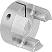
Precision Overload-Protection Spring-Loaded Torque Limiters
With zero backlash (no play), there’s no motion lost when these torque limiters transfer torque, so machines move smoothly with accurate and repeatable motion. They protect your machinery if there is a jam, emergency stop, or other overload by cutting off torque when a maximum torque is reached. They automatically resume transmitting torque once it drops below the set maximum. When they resume, they start transmitting torque from the same position where they stopped, keeping your drive and output sides in sync. They should not be used in applications that frequently exceed the set torque. You can adjust the set torque by using a spanner wrench to twist the adjustment ring.
To help you detect an overload, they have a sensor ring that moves out of place when these limiters cut off torque. Use a sensor (not included) to trigger an alarm or a shutdown when the ring moves.
They clamp evenly around your shaft for more holding power than set screws and won't damage your shaft.
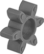
Shaft-to-shaft torque limiters also act as a flexible shaft coupling, so they compensate for angular and parallel misalignment as they regulate torque transmission between shafts. This reduces vibration and protects components from wear. For a complete unit, you’ll need a torque limiter, a hub, and a spider (all sold separately).
Through-shaft torque limiters regulate torque transmission between an input shaft and a mounted component, such as a pulley, sprocket, or gear.
Torque Limiters | Spiders | ||||||||||||||
|---|---|---|---|---|---|---|---|---|---|---|---|---|---|---|---|
Torque, in.-lbs. | Hubs | Misalignment Capability | |||||||||||||
| For Shaft Dia. | Min. | Max. | OD | O'all Lg. | Each | For Shaft Dia. | Each | Max. Speed, rpm | Parallel | Angular | Temp. Range, °F | Each | |||
For Round Shafts | |||||||||||||||
| 1/4" | 9 | 25 | 1 3/8" | 2" | 4404N11 | 0000000 | 4404N25 | 000000 | 15,000 | 0.003" | 1° | 0° to 180° | 4404N24 | 000000 | |
| 3/8" | 9 | 25 | 1 3/8" | 2" | 4404N12 | 000000 | 4404N25 | 00000 | 15,000 | 0.003" | 1° | 0° to 180° | 4404N24 | 00000 | |
| 3/8" | 18 | 50 | 1 3/4" | 2 3/8" | 4404N13 | 000000 | 4404N26 | 00000 | 10,000 | 0.011" | 1° | 0° to 180° | 9939T11 | 00000 | |
| 1/2" | 36 | 100 | 1 3/4" | 2 3/8" | 4404N14 | 000000 | 4404N26 | 00000 | 10,000 | 0.011" | 1° | 0° to 180° | 9939T11 | 00000 | |
For Keyed Shafts | |||||||||||||||
| 1/2" | 90 | 220 | 2 9/16" | 3 3/8" | 4404N15 | 000000 | 4404N27 | 00000 | 9,000 | 0.011" | 1° | 0° to 180° | 9939T14 | 00000 | |
| 5/8" | 90 | 220 | 2 9/16" | 3 3/8" | 4404N16 | 000000 | 4404N27 | 00000 | 9,000 | 0.011" | 1° | 0° to 180° | 9939T14 | 00000 | |
| 5/8" | 225 | 705 | 2 7/8" | 3 13/16" | 4404N18 | 000000 | 4404N28 | 000000 | 8,000 | 0.011" | 1° | 0° to 180° | 9939T17 | 00000 | |
| 3/4" | 90 | 220 | 2 9/16" | 3 3/8" | 4404N17 | 000000 | 4404N27 | 00000 | 9,000 | 0.011" | 1° | 0° to 180° | 9939T14 | 00000 | |
| 3/4" | 225 | 705 | 2 7/8" | 3 13/16" | 4404N19 | 000000 | 4404N28 | 000000 | 8,000 | 0.011" | 1° | 0° to 180° | 9939T17 | 00000 | |
| 1" | 225 | 705 | 2 7/8" | 3 13/16" | 4404N21 | 000000 | 4404N28 | 000000 | 8,000 | 0.011" | 1° | 0° to 180° | 9939T17 | 00000 | |
| 1" | 710 | 1,590 | 3 5/8" | 4 3/16" | 4404N22 | 00000000 | 4404N29 | 000000 | 7,000 | 0.011" | 1° | 0° to 180° | 9939T21 | 00000 | |
| 1 1/4" | 710 | 1,590 | 3 5/8" | 4 3/16" | 4404N23 | 00000000 | 4404N29 | 000000 | 7,000 | 0.011" | 1° | 0° to 180° | 9939T21 | 00000 | |
Torque, in.-lbs. | ||||||||||
|---|---|---|---|---|---|---|---|---|---|---|
| For Shaft Dia. | Min. | Max. | Max. Speed, rpm | OD | Overall Lg. | Keyway Wd. × Keyway Dp. | Material | Drive Direction | Each | |
For Round Shafts | ||||||||||
| 1/4" | 1.8 | 13 | 10,000 | 1 1/4" | 1 1/8" | __ | Steel | Clockwise and Counterclockwise | 4404N31 | 0000000 |
| 1/4" | 18 | 39 | 9,000 | 1 9/16" | 1 1/4" | __ | Steel | Clockwise and Counterclockwise | 4404N32 | 000000 |
| 3/8" | 18 | 39 | 9,000 | 1 9/16" | 1 1/4" | __ | Steel | Clockwise and Counterclockwise | 4404N33 | 000000 |
| 3/8" | 45 | 130 | 8,000 | 2 3/16" | 1 9/16" | __ | Steel | Clockwise and Counterclockwise | 4404N35 | 000000 |
| 1/2" | 36 | 105 | 8,000 | 2" | 1 9/16" | __ | Steel | Clockwise and Counterclockwise | 4404N34 | 000000 |
For Keyed Shafts | ||||||||||
| 1/2" | 90 | 265 | 6,000 | 2 9/16" | 2" | 1/8" × 1/16" | Steel | Clockwise and Counterclockwise | 4404N36 | 000000 |
| 5/8" | 90 | 265 | 6,000 | 2 9/16" | 2" | 3/16" × 3/32" | Steel | Clockwise and Counterclockwise | 4404N37 | 000000 |
| 5/8" | 180 | 615 | 4,000 | 3 5/8" | 2 5/16" | 3/16" × 3/32" | Steel | Clockwise and Counterclockwise | 4404N41 | 000000 |
| 3/4" | 90 | 265 | 6,000 | 2 9/16" | 2" | 3/16" × 3/32" | Steel | Clockwise and Counterclockwise | 4404N38 | 000000 |
| 3/4" | 225 | 705 | 6,000 | 2 7/8" | 2 1/8" | 3/16" × 3/32" | Steel | Clockwise and Counterclockwise | 4404N39 | 000000 |
| 1" | 400 | 1,325 | 4,000 | 3 5/8" | 2 5/16" | 1/4" × 1/8" | Steel | Clockwise and Counterclockwise | 4404N42 | 000000 |
| 1 1/4" | 710 | 1,990 | 4,000 | 3 5/8" | 2 5/16" | 1/4" × 1/8" | Steel | Clockwise and Counterclockwise | 4404N43 | 000000 |
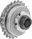
High-Torque Friction Torque Limiters
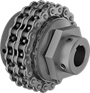
With rugged roller chains, these torque limiters handle more torque than other torque limiters. They have a disc that creates friction to prevent torque overload, control tension, and brake. If there’s too much torque, they’ll slip and only transmit the set torque. For example, they could be used in a machine that tightens a bottle cap to a certain torque without overtightening and breaking the bottle. Because they rely on friction, exposing them to moisture, oil, or lubricants can affect their performance. You can adjust the torque by rotating the hex nut on the hub.
They act as a flexible shaft coupling, so they reduce vibration and protect components from wear by compensating for angular and parallel misalignment. Fasten them to your shafts by tightening the set screws, which bite into each shaft to hold it.
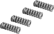
Single-spring torque limiters let you make finer torque adjustments than double-spring torque limiters but can only withstand half as much torque.
Double-spring torque limiters handle twice as much torque as single-spring torque limiters but are not the best for making precise adjustments at low torques.
Torque, ft.-lbs. | Misalignment Capability | Roller Chain | ||||||||||||
|---|---|---|---|---|---|---|---|---|---|---|---|---|---|---|
| For Shaft Dia. | For Shaft Type | Min. | Max. | Max. Speed, rpm | Parallel | Angular | OD | Overall Lg. | Keyway Wd. × Keyway Dp. | Drive Direction | Standard | Trade Size | Each | |
Single Spring | ||||||||||||||
| 1/2" × 1/2" | Round × Round | 0 | 25 | 1,800 | 0.01" | 3° | 2 3/4" | 2 1/4" | __ | Clockwise and Counterclockwise | ANSI | 35-2 | 4782N111 | 0000000 |
| 1/2" × 5/8" | Round × Keyed | 0 | 25 | 1,800 | 0.01" | 3° | 2 3/4" | 2 1/4" | 3/16" × 3/32" | Clockwise and Counterclockwise | ANSI | 35-2 | 4782N113 | 000000 |
| 1/2" × 3/4" | Round × Keyed | 0 | 25 | 1,800 | 0.01" | 3° | 2 3/4" | 2 1/4" | 3/16" × 3/32" | Clockwise and Counterclockwise | ANSI | 35-2 | 4782N115 | 000000 |
| 5/8" × 5/8" | Keyed × Keyed | 0 | 25 | 1,800 | 0.01" | 3° | 2 3/4" | 2 1/4" | 3/16" × 3/32" 3/16" × 3/32" | Clockwise and Counterclockwise | ANSI | 35-2 | 4782N117 | 000000 |
| 5/8" × 3/4" | Keyed × Keyed | 0 | 25 | 1,800 | 0.01" | 3° | 2 3/4" | 2 1/4" | 3/16" × 3/32" 3/16" × 3/32" | Clockwise and Counterclockwise | ANSI | 35-2 | 4782N119 | 000000 |
| 3/4" × 3/4" | Keyed × Keyed | 0 | 25 | 1,800 | 0.01" | 3° | 2 3/4" | 2 1/4" | 3/16" × 3/32" 3/16" × 3/32" | Clockwise and Counterclockwise | ANSI | 35-2 | 4782N122 | 000000 |
| 1" × 1" | Keyed × Keyed | 0 | 75 | 1,800 | 0.01" | 3° | 3 11/16" | 2 13/16" | 1/4" × 1/8" 1/4" × 1/8" | Clockwise and Counterclockwise | ANSI | 40-2 | 4782N131 | 000000 |
| 12mm × 12mm | Keyed × Keyed | 0 | 25 | 1,800 | 0.01" | 3° | 2 3/4" | 2 1/4" | 4mm × 2mm 4mm × 2mm | Clockwise and Counterclockwise | ANSI | 35-2 | 4782N124 | 000000 |
| 12mm × 15mm | Keyed × Keyed | 0 | 25 | 1,800 | 0.01" | 3° | 2 3/4" | 2 1/4" | 4mm × 2mm 5mm × 2.5mm | Clockwise and Counterclockwise | ANSI | 35-2 | 4782N126 | 000000 |
| 15mm × 15mm | Keyed × Keyed | 0 | 25 | 1,800 | 0.01" | 3° | 2 3/4" | 2 1/4" | 5mm × 2.5mm 5mm × 2.5mm | Clockwise and Counterclockwise | ANSI | 35-2 | 4782N128 | 000000 |
| 15mm × 20mm | Keyed × Keyed | 0 | 75 | 1,800 | 0.01" | 3° | 3 11/16" | 2 13/16" | 5mm × 2.5mm 6mm × 3mm | Clockwise and Counterclockwise | ANSI | 40-2 | 4782N133 | 000000 |
| 20mm × 20mm | Keyed × Keyed | 0 | 75 | 1,800 | 0.01" | 3° | 3 11/16" | 2 13/16" | 6mm × 3mm 6mm × 3mm | Clockwise and Counterclockwise | ANSI | 40-2 | 4782N135 | 000000 |
| 20mm × 25mm | Keyed × Keyed | 0 | 75 | 1,800 | 0.01" | 3° | 3 11/16" | 2 13/16" | 6mm × 3mm 8mm × 4mm | Clockwise and Counterclockwise | ANSI | 40-2 | 4782N137 | 000000 |
| 25mm × 25mm | Keyed × Keyed | 0 | 75 | 1,800 | 0.01" | 3° | 3 11/16" | 2 13/16" | 8mm × 4mm 8mm × 4mm | Clockwise and Counterclockwise | ANSI | 40-2 | 4782N139 | 000000 |
Double Spring | ||||||||||||||
| 1/2" × 1/2" | Round × Round | 0 | 50 | 1,800 | 0.01" | 3° | 2 3/4" | 2 1/4" | __ | Clockwise and Counterclockwise | ANSI | 35-2 | 4782N112 | 000000 |
| 1/2" × 5/8" | Round × Keyed | 0 | 50 | 1,800 | 0.01" | 3° | 2 3/4" | 2 1/4" | 3/16" × 3/32" | Clockwise and Counterclockwise | ANSI | 35-2 | 4782N114 | 000000 |
| 1/2" × 3/4" | Round × Keyed | 0 | 50 | 1,800 | 0.01" | 3° | 2 3/4" | 2 1/4" | 3/16" × 3/32" | Clockwise and Counterclockwise | ANSI | 35-2 | 4782N116 | 000000 |
| 5/8" × 5/8" | Keyed × Keyed | 0 | 50 | 1,800 | 0.01" | 3° | 2 3/4" | 2 1/4" | 3/16" × 3/32" 3/16" × 3/32" | Clockwise and Counterclockwise | ANSI | 35-2 | 4782N118 | 000000 |
| 5/8" × 3/4" | Keyed × Keyed | 0 | 50 | 1,800 | 0.01" | 3° | 2 3/4" | 2 1/4" | 3/16" × 3/32" 3/16" × 3/32" | Clockwise and Counterclockwise | ANSI | 35-2 | 4782N121 | 000000 |
| 3/4" × 3/4" | Keyed × Keyed | 0 | 50 | 1,800 | 0.01" | 3° | 2 3/4" | 2 1/4" | 3/16" × 3/32" 3/16" × 3/32" | Clockwise and Counterclockwise | ANSI | 35-2 | 4782N123 | 000000 |
| 1" × 1" | Keyed × Keyed | 0 | 150 | 1,800 | 0.01" | 3° | 3 11/16" | 2 13/16" | 1/4" × 1/8" 1/4" × 1/8" | Clockwise and Counterclockwise | ANSI | 40-2 | 4782N132 | 000000 |
| 12mm × 12mm | Keyed × Keyed | 0 | 50 | 1,800 | 0.01" | 3° | 2 3/4" | 2 1/4" | 4mm × 2mm 4mm × 2mm | Clockwise and Counterclockwise | ANSI | 35-2 | 4782N125 | 000000 |
| 12mm × 15mm | Keyed × Keyed | 0 | 50 | 1,800 | 0.01" | 3° | 2 3/4" | 2 1/4" | 4mm × 2mm 5mm × 2.5mm | Clockwise and Counterclockwise | ANSI | 35-2 | 4782N127 | 000000 |
| 15mm × 15mm | Keyed × Keyed | 0 | 50 | 1,800 | 0.01" | 3° | 2 3/4" | 2 1/4" | 5mm × 2.5mm 5mm × 2.5mm | Clockwise and Counterclockwise | ANSI | 35-2 | 4782N129 | 000000 |
| 15mm × 20mm | Keyed × Keyed | 0 | 150 | 1,800 | 0.01" | 3° | 3 11/16" | 2 13/16" | 5mm × 2.5mm 6mm × 3mm | Clockwise and Counterclockwise | ANSI | 40-2 | 4782N134 | 000000 |
| 20mm × 20mm | Keyed × Keyed | 0 | 150 | 1,800 | 0.01" | 3° | 3 11/16" | 2 13/16" | 6mm × 3mm 6mm × 3mm | Clockwise and Counterclockwise | ANSI | 40-2 | 4782N136 | 000000 |
| 20mm × 25mm | Keyed × Keyed | 0 | 150 | 1,800 | 0.01" | 3° | 3 11/16" | 2 13/16" | 6mm × 3mm 8mm × 4mm | Clockwise and Counterclockwise | ANSI | 40-2 | 4782N138 | 000000 |
| 25mm × 25mm | Keyed × Keyed | 0 | 150 | 1,800 | 0.01" | 3° | 3 11/16" | 2 13/16" | 8mm × 4mm 8mm × 4mm | Clockwise and Counterclockwise | ANSI | 40-2 | 4782N141 | 000000 |
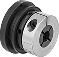
Corrosion-Resistant Overload-Protection Spring-Loaded Torque Limiters
Prevent corrosion from interfering with these torque limiters’ ability to protect your machinery if there’s a jam, emergency stop, or other overload. Made of nylon, they won’t rust or corrode from moisture, salt, and oil. They cut off torque when they reach the set maximum torque and automatically resume transmitting torque once it drops below the set maximum. They should not be used in applications that frequently exceed the set torque. You can adjust the set torque by tightening the hex head screw on the housing.
To help you detect an overload, these torque limiters have a sensor ring that moves out of place when these limiters cut off torque. Use a sensor (not included) to trigger an alarm or a shutdown when the ring moves.
Fasten them to your shaft by tightening the set screws, which bite into the shaft to hold it.
Shaft-to-shaft torque limiters also act as a shaft coupling, allowing you to regulate torque transmission between two shafts.
Through-shaft torque limiters regulate torque transmission between an input shaft and a mounted component, such as a pulley, sprocket, or gear.
Spring kits let you change the torque range on your torque limiter.
Torque | Misalignment Capability | |||||||||||||||
|---|---|---|---|---|---|---|---|---|---|---|---|---|---|---|---|---|
| For Shaft Dia. | For Shaft Type | Min., in.-lbs. | Max., in.-lbs. | Max. Speed, rpm | Parallel | Angular | OD | Overall Lg. | Keyway Wd. × Keyway Dp. | No. of Springs | Material | Drive Direction | Re-Engagement Position | Features | Each | |
Shaft-to-Shaft | ||||||||||||||||
| 1/4" | Round | 4 | 60 | 1,800 | 0.01" | 1° | 2 1/2" | 2 1/2" | __ | 4 | Nylon Plastic | Clockwise and Counterclockwise | Multiple Position | Sensor Ring | 4410N101 | 0000000 |
| 3/8" | Round | 4 | 60 | 1,800 | 0.01" | 1° | 2 1/2" | 2 1/2" | __ | 4 | Nylon Plastic | Clockwise and Counterclockwise | Multiple Position | Sensor Ring | 4410N102 | 000000 |
| 1/2" | Keyed | 4 | 60 | 1,800 | 0.01" | 1° | 2 1/2" | 2 1/2" | 1/8" × 1/16" | 4 | Nylon Plastic | Clockwise and Counterclockwise | Multiple Position | Sensor Ring | 4410N103 | 000000 |
| 1/2" | Keyed | 40 | 150 | 1,800 | 0.01" | 1° | 4 1/32" | 3 7/16" | 1/8" × 1/16" | 6 | Nylon Plastic | Clockwise and Counterclockwise | Multiple Position | Sensor Ring | 4410N104 | 000000 |
| 5/8" | Keyed | 40 | 150 | 1,800 | 0.01" | 1° | 4 1/32" | 3 7/16" | 3/16" × 3/32" | 6 | Nylon Plastic | Clockwise and Counterclockwise | Multiple Position | Sensor Ring | 4410N105 | 000000 |
| 3/4" | Keyed | 40 | 150 | 1,800 | 0.01" | 1° | 4 1/32" | 3 7/16" | 3/16" × 3/32" | 6 | Nylon Plastic | Clockwise and Counterclockwise | Multiple Position | Sensor Ring | 4410N106 | 000000 |
| 1" | Keyed | 40 | 150 | 1,800 | 0.01" | 1° | 4 1/32" | 3 7/16" | 1/4" × 1/8" | 6 | Nylon Plastic | Clockwise and Counterclockwise | Multiple Position | Sensor Ring | 4410N107 | 000000 |
Through Shaft | ||||||||||||||||
| 1/4" | Round | 4 | 60 | 1,800 | __ | __ | 2 1/2" | 2 1/2" | __ | 4 | Nylon Plastic | Clockwise and Counterclockwise | Multiple Position | Sensor Ring | 4410N108 | 000000 |
| 3/8" | Round | 4 | 60 | 1,800 | __ | __ | 2 1/2" | 2 1/2" | __ | 4 | Nylon Plastic | Clockwise and Counterclockwise | Multiple Position | Sensor Ring | 4410N109 | 000000 |
| 1/2" | Keyed | 4 | 60 | 1,800 | __ | __ | 2 1/2" | 2 1/2" | 1/8" × 1/16" | 4 | Nylon Plastic | Clockwise and Counterclockwise | Multiple Position | Sensor Ring | 4410N111 | 000000 |
| 1/2" | Keyed | 40 | 150 | 1,800 | __ | __ | 4 1/32" | 3 7/16" | 1/8" × 1/16" | 6 | Nylon Plastic | Clockwise and Counterclockwise | Multiple Position | Sensor Ring | 4410N112 | 000000 |
| 5/8" | Keyed | 40 | 150 | 1,800 | __ | __ | 4 1/32" | 3 7/16" | 3/16" × 3/32" | 6 | Nylon Plastic | Clockwise and Counterclockwise | Multiple Position | Sensor Ring | 4410N113 | 000000 |
| 3/4" | Keyed | 40 | 150 | 1,800 | __ | __ | 4 1/32" | 3 7/16" | 3/16" × 3/32" | 6 | Nylon Plastic | Clockwise and Counterclockwise | Multiple Position | Sensor Ring | 4410N114 | 000000 |
| 1" | Keyed | 40 | 150 | 1,800 | __ | __ | 4 1/32" | 3 7/16" | 1/4" × 1/8" | 6 | Nylon Plastic | Clockwise and Counterclockwise | Multiple Position | Sensor Ring | 4410N115 | 000000 |
Remote-Adjust Air-Powered Friction Torque Limiters

Use your air system to remotely make changes to the torque setting or cut off torque completely, even during operation. Adjust the torque setting by adjusting the air pressure—the higher the pressure, the higher the set torque. When these torque limiters exceed their set torque, they’ll slip but still transmit the set torque. They use friction to prevent torque overload, control tension, and brake. They’re often used in automated systems. For instance, they can be used in a machine that tightens a bottle cap to a certain torque without overtightening it and breaking the bottle. Because they rely on friction, exposing them to moisture, oil, or lubricants can affect their performance.
Fasten them to your shaft by tightening the set screws, which bite into the shaft to hold it.
Shaft-to-shaft torque limiters also act as a shaft coupling, allowing you to regulate torque transmission between two shafts.
Through-shaft torque limiters regulate torque transmission between an input shaft and a mounted component, such as a pulley, sprocket, or gear.
Torque | Keyway | Air Inlet | ||||||||||||
|---|---|---|---|---|---|---|---|---|---|---|---|---|---|---|
| For Shaft Dia. | Min., in.-lbs. | Max., in.-lbs. | Max. Pressure, psi | Max. Speed | OD | Overall Lg. | Wd. | Dp. | Drive Direction | Thread Size | Thread Type | Gender | Each | |
Shaft-to-Shaft | ||||||||||||||
For Round Shafts | ||||||||||||||
| 1/4" | 2 | 20 | 100 | Not Rated | 1 1/4" | 2 1/2" | __ | __ | Clockwise and Counterclockwise | 10-32 | UNF | Female | 9133K11 | 0000000 |
| 3/8" | 5 | 50 | 100 | Not Rated | 1 1/2" | 3 3/8" | __ | __ | Clockwise and Counterclockwise | 10-32 | UNF | Female | 9133K12 | 000000 |
| 1/2" | 10 | 100 | 100 | Not Rated | 2" | 3 5/8" | __ | __ | Clockwise and Counterclockwise | 10-32 | UNF | Female | 9133K15 | 000000 |
| 5/8" | 30 | 300 | 100 | Not Rated | 2 3/4" | 3 5/8" | __ | __ | Clockwise and Counterclockwise | 10-32 | UNF | Female | 9133K19 | 000000 |
For Keyed Shafts | ||||||||||||||
| 1/2" | 10 | 100 | 100 | Not Rated | 2" | 3 5/8" | 1/8" | 1/16" | Clockwise and Counterclockwise | 10-32 | UNF | Female | 9133K53 | 000000 |
| 5/8" | 30 | 300 | 100 | Not Rated | 2 3/4" | 3 5/8" | 3/16" | 3/32" | Clockwise and Counterclockwise | 10-32 | UNF | Female | 9133K54 | 000000 |
Through Shaft | ||||||||||||||
For Round Shafts | ||||||||||||||
| 1/4" | 2 | 20 | 100 | Not Rated | 1 1/4" | 2 1/2" | __ | __ | Clockwise and Counterclockwise | 10-32 | UNF | Female | 9133K31 | 000000 |
| 3/8" | 5 | 50 | 100 | Not Rated | 1 1/2" | 3 3/8" | __ | __ | Clockwise and Counterclockwise | 10-32 | UNF | Female | 9133K32 | 000000 |
| 1/2" | 10 | 100 | 100 | Not Rated | 2" | 3 5/8" | __ | __ | Clockwise and Counterclockwise | 10-32 | UNF | Female | 9133K33 | 000000 |
For Keyed Shafts | ||||||||||||||
| 5/8" | 30 | 300 | 100 | Not Rated | 2 3/4" | 3 5/8" | 3/16" | 3/32" | Clockwise and Counterclockwise | 10-32 | UNF | Female | 9133K44 | 000000 |
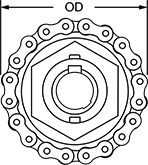
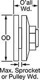
Torque Limiters for Chain and Belt Drives
Prevent damage from overloading. When overloaded, these limiters cause your sprocket or pulley to slip. Once the overload is removed, the limiters automatically reset. Set the torque within the range listed. Friction discs are between the hub and pressure plate.
Double-spring limiters have a second spring for handling nearly twice the torque of single-spring limiters.
Optional sprockets are designed specifically to fit their corresponding limiters. These hubless sprockets are not interchangeable.
Torque Limiters | |||||||||||||||||||
|---|---|---|---|---|---|---|---|---|---|---|---|---|---|---|---|---|---|---|---|
Keyway | Torque | Optional Sprockets | Replacement Friction Discs for Torque Limiters | Replacement Bushings for Optional Sprockets | |||||||||||||||
| For Shaft Dia. | OD | O'all Wd. | Wd. | Dp. | For Max. Sprocket or Pulley Wd. | Friction Disc Thick. | Min., ft.-lbs. | Max., ft.-lbs. | Hub Material | Each | For Roller Chain Trade Size | Each | Each | For Roller Chain Trade Size | Each | ||||
Single Spring | |||||||||||||||||||
| 1/4" | 1 5/16" | 1 3/8" | 1/16" | 1/32" | 11/32" | 1/8" | 1 | 6 | Steel | 6524K171 | 000000 | 6525K27 | 000000 | 6525K68 | 000000 | __ | ______ | 00 | |
| 5/16" | 1 5/16" | 1 3/8" | 3/32" | 3/64" | 11/32" | 1/8" | 1 | 6 | Steel | 6524K172 | 00000 | 6525K27 | 00000 | 6525K68 | 00000 | __ | ______ | 00 | |
| 3/8" | 1 5/16" | 1 3/8" | 3/32" | 3/64" | 11/32" | 1/8" | 1 | 6 | Steel | 6524K173 | 00000 | 6525K27 | 00000 | 6525K68 | 00000 | __ | ______ | 00 | |
| 3/8" | 2 1/4" | 2" | 3/32" | 3/64" | 1/2" | 1/8" | 5 | 35 | Steel | 6524K111 | 000000 | 6525K11 | 00000 | 6525K62 | 00000 | __ | ______ | 00 | |
| 1/2" | 2 1/4" | 2" | 1/8" | 1/16" | 1/2" | 1/8" | 5 | 35 | Steel | 6524K18 | 000000 | 6525K11 | 00000 | 6525K62 | 00000 | __ | ______ | 00 | |
| 1/2" | 2 1/2" | 1 3/4" | 1/8" | 1/16" | 11/32" | 1/8" | 25 | 60 | Steel | 6524K121 | 00000 | 6525K12 | 00000 | 6525K64 | 0000 | 6525K6 | 00000 | ||
| 1/2" | 3 3/8" | 2 1/8" | 1/8" | 1/16" | 1/2" | 1/8" | 11 | 100 | Steel | 6524K131 | 000000 | 6525K13 | 00000 | 6525K63 | 00000 | __ | ______ | 00 | |
| 5/8" | 2 1/4" | 2" | 3/16" | 3/32" | 1/2" | 1/8" | 5 | 35 | Steel | 6524K19 | 000000 | 6525K11 | 00000 | 6525K62 | 00000 | __ | ______ | 00 | |
| 5/8" | 2 1/2" | 1 3/4" | 3/16" | 3/32" | 11/32" | 1/8" | 25 | 60 | Steel | 6524K122 | 00000 | 6525K12 | 00000 | 6525K64 | 0000 | 6525K6 | 0000 | ||
| 5/8" | 3 3/8" | 2 1/8" | 3/16" | 3/32" | 1/2" | 1/8" | 11 | 100 | Steel | 6524K27 | 000000 | 6525K13 | 00000 | 6525K63 | 00000 | __ | ______ | 00 | |
| 3/4" | 2 1/4" | 2" | 3/16" | 3/32" | 1/2" | 1/8" | 5 | 35 | Steel | 6524K21 | 000000 | 6525K11 | 00000 | 6525K62 | 00000 | __ | ______ | 00 | |
| 3/4" | 2 1/2" | 1 3/4" | 3/16" | 3/32" | 11/32" | 1/8" | 25 | 60 | Steel | 6524K123 | 00000 | 6525K12 | 00000 | 6525K64 | 0000 | 6525K6 | 0000 | ||
| 3/4" | 3 3/8" | 2 1/8" | 3/16" | 3/32" | 1/2" | 1/8" | 11 | 100 | Steel | 6524K28 | 000000 | 6525K13 | 00000 | 6525K63 | 00000 | __ | ______ | 00 | |
| 3/4" | 3 1/2" | 2 3/16" | 3/16" | 3/32" | 1/2" | 1/8" | 50 | 120 | Steel | 6524K141 | 000000 | 6525K14 | 00000 | 6525K65 | 00000 | 6525K7 | 0000 | ||
| 3/4" | 4 1/2" | 2 7/8" | 3/16" | 3/32" | 7/8" | 1/8" | 18 | 190 | Steel | 6524K321 | 000000 | 6525K32 | 00000 | 6525K72 | 00000 | __ | ______ | 00 | |
| 7/8" | 2 1/2" | 1 3/4" | 3/16" | 3/32" | 11/32" | 1/8" | 25 | 60 | Steel | 6524K124 | 00000 | 6525K12 | 00000 | 6525K64 | 0000 | 6525K6 | 0000 | ||
| 7/8" | 3 3/8" | 2 1/8" | 3/16" | 3/32" | 1/2" | 1/8" | 11 | 100 | Steel | 6524K29 | 000000 | 6525K13 | 00000 | 6525K63 | 00000 | __ | ______ | 00 | |
| 7/8" | 3 1/2" | 2 3/16" | 3/16" | 3/32" | 1/2" | 1/8" | 50 | 120 | Steel | 6524K142 | 000000 | 6525K14 | 00000 | 6525K65 | 00000 | 6525K7 | 0000 | ||
| 1" | 2 1/2" | 1 3/4" | 1/4" | 1/8" | 11/32" | 1/8" | 25 | 60 | Steel | 6524K501 | 00000 | 6525K12 | 00000 | 6525K64 | 0000 | 6525K6 | 0000 | ||
| 1" | 3 3/8" | 2 1/8" | 1/4" | 1/8" | 1/2" | 1/8" | 11 | 100 | Steel | 6524K31 | 000000 | 6525K13 | 00000 | 6525K63 | 00000 | __ | ______ | 00 | |
| 1" | 3 1/2" | 2 3/16" | 1/4" | 1/8" | 1/2" | 1/8" | 50 | 120 | Steel | 6524K143 | 000000 | 6525K14 | 00000 | 6525K65 | 00000 | 6525K7 | 0000 | ||
| 1" | 4 1/2" | 2 7/8" | 1/4" | 1/8" | 7/8" | 1/8" | 18 | 190 | Steel | 6524K322 | 000000 | 6525K32 | 00000 | 6525K72 | 00000 | __ | ______ | 00 | |
| 1" | 5" | 2 7/8" | 1/4" | 1/8" | 5/8" | 1/8" | 90 | 250 | Steel | 6524K151 | 000000 | 6525K15 | 00000 | 6525K66 | 00000 | 6525K8 | 00000 | ||
| 1" | 6" | 3" | 1/4" | 1/8" | 13/16" | 1/8" | 24 | 320 | Steel | 6524K125 | 000000 | 6525K33 | 000000 | 6525K73 | 00000 | __ | ______ | 00 | |
| 1 1/8" | 4 1/2" | 2 7/8" | 1/4" | 1/8" | 7/8" | 1/8" | 18 | 190 | Steel | 6524K323 | 000000 | 6525K32 | 00000 | 6525K72 | 00000 | __ | ______ | 00 | |
| 1 1/8" | 5" | 2 7/8" | 1/4" | 1/8" | 5/8" | 1/8" | 90 | 250 | Steel | 6524K152 | 000000 | 6525K15 | 00000 | 6525K66 | 00000 | 6525K8 | 00000 | ||
| 1 3/16" | 5" | 2 7/8" | 1/4" | 1/8" | 5/8" | 1/8" | 90 | 250 | Steel | 6524K153 | 000000 | 6525K15 | 00000 | 6525K66 | 00000 | 6525K8 | 00000 | ||
| 1 1/4" | 3 1/2" | 2 3/16" | 1/4" | 1/8" | 1/2" | 1/8" | 50 | 120 | Steel | 6524K503 | 000000 | 6525K14 | 00000 | 6525K65 | 00000 | 6525K7 | 0000 | ||
| 1 1/4" | 4 1/2" | 2 7/8" | 1/4" | 1/8" | 7/8" | 1/8" | 18 | 190 | Steel | 6524K324 | 000000 | 6525K32 | 00000 | 6525K72 | 00000 | __ | ______ | 00 | |
| 1 1/4" | 5" | 2 7/8" | 1/4" | 1/8" | 5/8" | 1/8" | 90 | 250 | Steel | 6524K154 | 000000 | 6525K15 | 00000 | 6525K66 | 00000 | 6525K8 | 00000 | ||
| 1 1/4" | 6" | 3" | 1/4" | 1/8" | 13/16" | 1/8" | 24 | 320 | Steel | 6524K126 | 000000 | 6525K33 | 000000 | 6525K73 | 00000 | __ | ______ | 00 | |
| 1 3/8" | 4 1/2" | 2 7/8" | 5/16" | 5/32" | 7/8" | 1/8" | 18 | 190 | Steel | 6524K325 | 000000 | 6525K32 | 00000 | 6525K72 | 00000 | __ | ______ | 00 | |
| 1 3/8" | 5" | 2 7/8" | 5/16" | 5/32" | 5/8" | 1/8" | 90 | 250 | Steel | 6524K155 | 000000 | 6525K15 | 00000 | 6525K66 | 00000 | 6525K8 | 00000 | ||
| 1 3/8" | 6" | 3" | 5/16" | 5/32" | 13/16" | 1/8" | 24 | 320 | Steel | 6524K127 | 000000 | 6525K33 | 000000 | 6525K73 | 00000 | __ | ______ | 00 | |
| 1 7/16" | 5" | 2 7/8" | 3/8" | 3/16" | 5/8" | 1/8" | 90 | 250 | Steel | 6524K156 | 000000 | 6525K15 | 00000 | 6525K66 | 00000 | 6525K8 | 00000 | ||
| 1 7/16" | 6" | 3" | 3/8" | 3/16" | 13/16" | 1/8" | 24 | 320 | Steel | 6524K138 | 000000 | 6525K33 | 000000 | 6525K73 | 00000 | __ | ______ | 00 | |
| 1 1/2" | 5" | 2 7/8" | 3/8" | 3/16" | 5/8" | 1/8" | 90 | 250 | Steel | 6524K157 | 000000 | 6525K15 | 00000 | 6525K66 | 00000 | 6525K8 | 00000 | ||
| 1 1/2" | 6" | 3" | 3/8" | 3/16" | 13/16" | 1/8" | 24 | 320 | Steel | 6524K128 | 000000 | 6525K33 | 000000 | 6525K73 | 00000 | __ | ______ | 00 | |
| 1 5/8" | 5" | 2 7/8" | 3/8" | 3/16" | 5/8" | 1/8" | 90 | 250 | Steel | 6524K158 | 000000 | 6525K15 | 00000 | 6525K66 | 00000 | 6525K8 | 00000 | ||
| 1 5/8" | 6" | 3" | 3/8" | 3/16" | 13/16" | 1/8" | 24 | 320 | Steel | 6524K129 | 000000 | 6525K33 | 000000 | 6525K73 | 00000 | __ | ______ | 00 | |
Double Spring | |||||||||||||||||||
| 1/4" | 1 5/16" | 1 3/8" | 1/16" | 1/32" | 5/16" | 1/8" | 2 | 12 | Steel | 6524K331 | 000000 | 6525K27 | 00000 | 6525K68 | 00000 | __ | ______ | 00 | |
| 5/16" | 1 5/16" | 1 3/8" | 3/32" | 3/64" | 5/16" | 1/8" | 2 | 12 | Steel | 6524K332 | 000000 | 6525K27 | 00000 | 6525K68 | 00000 | __ | ______ | 00 | |
| 3/8" | 1 5/16" | 1 3/8" | 3/32" | 3/64" | 5/16" | 1/8" | 2 | 12 | Steel | 6524K333 | 000000 | 6525K27 | 00000 | 6525K68 | 00000 | __ | ______ | 00 | |
| 3/8" | 2 1/4" | 2" | 3/32" | 3/64" | 15/32" | 1/8" | 7 | 50 | Steel | 6524K411 | 000000 | 6525K11 | 00000 | 6525K62 | 00000 | __ | ______ | 00 | |
| 1/2" | 2 1/4" | 2" | 1/8" | 1/16" | 15/32" | 1/8" | 7 | 50 | Steel | 6524K23 | 000000 | 6525K11 | 00000 | 6525K62 | 00000 | __ | ______ | 00 | |
| 1/2" | 2 1/2" | 1 3/4" | 1/8" | 1/16" | 11/32" | 1/8" | 30 | 95 | Steel | 6524K421 | 000000 | 6525K12 | 00000 | 6525K64 | 0000 | 6525K6 | 0000 | ||
| 1/2" | 3 3/8" | 2 1/8" | 1/8" | 1/16" | 7/16" | 1/8" | 13 | 175 | Steel | 6524K431 | 000000 | 6525K13 | 00000 | 6525K63 | 00000 | __ | ______ | 00 | |
| 5/8" | 2 1/4" | 2" | 3/16" | 3/32" | 15/32" | 1/8" | 7 | 50 | Steel | 6524K24 | 000000 | 6525K11 | 00000 | 6525K62 | 00000 | __ | ______ | 00 | |
| 5/8" | 2 1/2" | 1 3/4" | 3/16" | 3/32" | 11/32" | 1/8" | 30 | 95 | Steel | 6524K422 | 000000 | 6525K12 | 00000 | 6525K64 | 0000 | 6525K6 | 0000 | ||
| 5/8" | 3 3/8" | 2 1/8" | 3/16" | 3/32" | 7/16" | 1/8" | 13 | 175 | Steel | 6524K432 | 000000 | 6525K13 | 00000 | 6525K63 | 00000 | __ | ______ | 00 | |
| 3/4" | 2 1/4" | 2" | 3/16" | 3/32" | 15/32" | 1/8" | 7 | 50 | Steel | 6524K25 | 000000 | 6525K11 | 00000 | 6525K62 | 00000 | __ | ______ | 00 | |
| 3/4" | 2 1/2" | 1 3/4" | 3/16" | 3/32" | 11/32" | 1/8" | 30 | 95 | Steel | 6524K423 | 000000 | 6525K12 | 00000 | 6525K64 | 0000 | 6525K6 | 0000 | ||
| 3/4" | 3 3/8" | 2 1/8" | 3/16" | 3/32" | 7/16" | 1/8" | 13 | 175 | Steel | 6524K34 | 000000 | 6525K13 | 00000 | 6525K63 | 00000 | __ | ______ | 00 | |
| 3/4" | 3 1/2" | 2 3/16" | 3/16" | 3/32" | 1/2" | 1/8" | 60 | 190 | Steel | 6524K441 | 000000 | 6525K14 | 00000 | 6525K65 | 00000 | 6525K7 | 0000 | ||
| 3/4" | 4 1/2" | 2 7/8" | 3/16" | 3/32" | 13/16" | 1/8" | 20 | 285 | Steel | 6524K381 | 000000 | 6525K32 | 00000 | 6525K72 | 00000 | __ | ______ | 00 | |
| 7/8" | 2 1/2" | 1 3/4" | 3/16" | 3/32" | 11/32" | 1/8" | 30 | 95 | Steel | 6524K424 | 000000 | 6525K12 | 00000 | 6525K64 | 0000 | 6525K6 | 0000 | ||
| 7/8" | 3 3/8" | 2 1/8" | 3/16" | 3/32" | 7/16" | 1/8" | 13 | 175 | Steel | 6524K434 | 000000 | 6525K13 | 00000 | 6525K63 | 00000 | __ | ______ | 00 | |
| 7/8" | 3 1/2" | 2 3/16" | 3/16" | 3/32" | 1/2" | 1/8" | 60 | 190 | Steel | 6524K442 | 000000 | 6525K14 | 00000 | 6525K65 | 00000 | 6525K7 | 0000 | ||
| 1" | 2 1/2" | 1 3/4" | 1/4" | 1/8" | 11/32" | 1/8" | 30 | 95 | Steel | 6524K502 | 000000 | 6525K12 | 00000 | 6525K64 | 0000 | 6525K6 | 0000 | ||
| 1" | 3 3/8" | 2 1/8" | 1/4" | 1/8" | 7/16" | 1/8" | 13 | 175 | Steel | 6524K36 | 000000 | 6525K13 | 00000 | 6525K63 | 00000 | __ | ______ | 00 | |
| 1" | 3 1/2" | 2 3/16" | 1/4" | 1/8" | 1/2" | 1/8" | 60 | 190 | Steel | 6524K443 | 000000 | 6525K14 | 00000 | 6525K65 | 00000 | 6525K7 | 0000 | ||
| 1" | 4 1/2" | 2 7/8" | 1/4" | 1/8" | 13/16" | 1/8" | 20 | 285 | Steel | 6524K382 | 000000 | 6525K32 | 00000 | 6525K72 | 00000 | __ | ______ | 00 | |
| 1" | 5" | 2 7/8" | 1/4" | 1/8" | 5/8" | 1/8" | 120 | 400 | Steel | 6524K451 | 000000 | 6525K15 | 00000 | 6525K66 | 00000 | 6525K8 | 00000 | ||
| 1" | 6" | 3" | 1/4" | 1/8" | 3/4" | 1/8" | 26 | 440 | Steel | 6524K132 | 000000 | 6525K33 | 000000 | 6525K73 | 00000 | __ | ______ | 00 | |
| 1 1/8" | 4 1/2" | 2 7/8" | 1/4" | 1/8" | 13/16" | 1/8" | 20 | 285 | Steel | 6524K383 | 000000 | 6525K32 | 00000 | 6525K72 | 00000 | __ | ______ | 00 | |
| 1 1/8" | 5" | 2 7/8" | 1/4" | 1/8" | 5/8" | 1/8" | 120 | 400 | Steel | 6524K452 | 000000 | 6525K15 | 00000 | 6525K66 | 00000 | 6525K8 | 00000 | ||
| 1 3/16" | 5" | 2 7/8" | 1/4" | 1/8" | 5/8" | 1/8" | 120 | 400 | Steel | 6524K453 | 000000 | 6525K15 | 00000 | 6525K66 | 00000 | 6525K8 | 00000 | ||
| 1 1/4" | 3 1/2" | 2 3/16" | 1/4" | 1/8" | 1/2" | 1/8" | 60 | 190 | Steel | 6524K504 | 000000 | 6525K14 | 00000 | 6525K65 | 00000 | 6525K7 | 0000 | ||
| 1 1/4" | 4 1/2" | 2 7/8" | 1/4" | 1/8" | 13/16" | 1/8" | 20 | 285 | Steel | 6524K384 | 000000 | 6525K32 | 00000 | 6525K72 | 00000 | __ | ______ | 00 | |
| 1 1/4" | 5" | 2 7/8" | 1/4" | 1/8" | 5/8" | 1/8" | 120 | 400 | Steel | 6524K454 | 000000 | 6525K15 | 00000 | 6525K66 | 00000 | 6525K8 | 00000 | ||
| 1 1/4" | 6" | 3" | 1/4" | 1/8" | 3/4" | 1/8" | 26 | 440 | Steel | 6524K133 | 000000 | 6525K33 | 000000 | 6525K73 | 00000 | __ | ______ | 00 | |
| 1 3/8" | 4 1/2" | 2 7/8" | 5/16" | 5/32" | 13/16" | 1/8" | 20 | 285 | Steel | 6524K385 | 000000 | 6525K32 | 00000 | 6525K72 | 00000 | __ | ______ | 00 | |
| 1 3/8" | 5" | 2 7/8" | 5/16" | 5/32" | 5/8" | 1/8" | 120 | 400 | Steel | 6524K455 | 000000 | 6525K15 | 00000 | 6525K66 | 00000 | 6525K8 | 00000 | ||
| 1 3/8" | 6" | 3" | 5/16" | 5/32" | 3/4" | 1/8" | 26 | 440 | Steel | 6524K134 | 000000 | 6525K33 | 000000 | 6525K73 | 00000 | __ | ______ | 00 | |
| 1 7/16" | 5" | 2 7/8" | 3/8" | 3/16" | 5/8" | 1/8" | 120 | 400 | Steel | 6524K456 | 000000 | 6525K15 | 00000 | 6525K66 | 00000 | 6525K8 | 00000 | ||
| 1 7/16" | 6" | 3" | 3/8" | 3/16" | 3/4" | 1/8" | 26 | 440 | Steel | 6524K137 | 000000 | 6525K33 | 000000 | 6525K73 | 00000 | __ | ______ | 00 | |
| 1 1/2" | 5" | 2 7/8" | 3/8" | 3/16" | 5/8" | 1/8" | 120 | 400 | Steel | 6524K457 | 000000 | 6525K15 | 00000 | 6525K66 | 00000 | 6525K8 | 00000 | ||
| 1 1/2" | 6" | 3" | 3/8" | 3/16" | 3/4" | 1/8" | 26 | 440 | Steel | 6524K135 | 000000 | 6525K33 | 000000 | 6525K73 | 00000 | __ | ______ | 00 | |
| 1 5/8" | 5" | 2 7/8" | 3/8" | 3/16" | 5/8" | 1/8" | 120 | 400 | Steel | 6524K458 | 000000 | 6525K15 | 00000 | 6525K66 | 00000 | 6525K8 | 00000 | ||
| 1 5/8" | 6" | 3" | 3/8" | 3/16" | 3/4" | 1/8" | 26 | 440 | Steel | 6524K136 | 000000 | 6525K33 | 000000 | 6525K73 | 00000 | __ | ______ | 00 | |