


Latching Distance Latching Distance |
|---|
For Maximum Thickness For Maximum Thickness |
|---|
|
Material Material |
|---|
|
Turn Direction Turn Direction |
|---|
|
Cam Style Cam Style |
|---|
|
DFARS (Defense Acquisition Regulations Supplement) DFARS (Defense AcquisitionRegulations Supplement) |
|---|
RoHS (Restriction of Hazardous Substances) RoHS (Restriction ofHazardous Substances) |
|---|
|
REACH (Registration, Evaluation, Authorization and Restriction of Chemicals) REACH (Registration,Evaluation, Authorization and Restriction of Chemicals) |
|---|
|
About Cam Latches and Locks
More
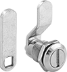
Washdown Slotted-Drive Cam Locks
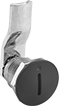
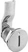

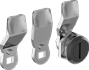
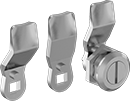
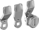
For protection against dust, dirt, and washdowns, these locks are IP65 rated. Select the turn direction when mounting the cam.
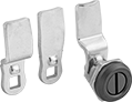
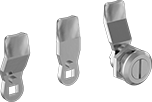
Style B comes with one straight and two nonreversible offset cams to accommodate different latching distances.
Style C comes with three nonreversible offset cams to accommodate different latching distances.
Offset Cam | ||||||||||
|---|---|---|---|---|---|---|---|---|---|---|
| For Max. Thick. | Latching Distance | For Through Hole Dia. | Head Dia. | Lg. | Wd. | Mounting Fasteners Included | For Use On | Environmental Rating | Each | |
Style A, Black Powder-Coated Zinc | ||||||||||
| 35/64" | 5/8" | 7/8" | 1 1/4" | 1 3/4" | 3/4" | Yes | Metal | IP65, NEMA 4 | 00000000 | 00000 |
Style A, Chrome-Plated Zinc—Polished | ||||||||||
| 35/64" | 5/8" | 7/8" | 1 1/4" | 1 3/4" | 3/4" | Yes | Metal | IP65, NEMA 4 | 00000000 | 00000 |
Style B, Black Powder-Coated Zinc | ||||||||||
| 3/16" | 5/16", 11/16", 1 1/8" | 7/8" | 1 1/8" | 1 3/4" | 3/4" | Yes | Metal | IP65, NEMA 4 | 00000000 | 00000 |
| 5/16" | 11/16", 13/16", 1 1/16" | 7/8" | 1 1/8" | 1 3/4" | 3/4" | Yes | Metal | IP65 | 000000000 | 00000 |
| 25/32" | 1 3/16", 1 11/32", 1 37/64" | 7/8" | 1 1/8" | 1 3/4" | 3/4" | Yes | Metal | IP65 | 000000000 | 00000 |
| 1" | 1 27/64", 1 37/64", 1 13/16" | 7/8" | 1 1/8" | 1 3/4" | 3/4" | Yes | Metal | IP65 | 000000000 | 00000 |
| 1 3/16" | 1 37/64", 1 47/64", 1 31/32" | 7/8" | 1 1/8" | 1 3/4" | 3/4" | Yes | Metal | IP65 | 000000000 | 00000 |
| 1 37/64" | 1 31/32", 2 1/8", 2 23/64" | 7/8" | 1 1/8" | 1 3/4" | 3/4" | Yes | Metal | IP65 | 000000000 | 00000 |
| 1 31/32" | 2 23/64", 2 33/64", 2 3/4" | 7/8" | 1 1/8" | 1 3/4" | 3/4" | Yes | Metal | IP65 | 000000000 | 00000 |
Style B, Chrome-Plated Zinc—Polished | ||||||||||
| 3/16" | 5/16", 11/16", 1 1/8" | 7/8" | 1 1/8" | 1 3/4" | 3/4" | Yes | Metal | IP65, NEMA 4 | 00000000 | 00000 |
| 5/16" | 45/64", 55/64", 1 3/32" | 7/8" | 1 1/8" | 1 3/4" | 3/4" | Yes | Metal | IP65 | 000000000 | 00000 |
| 25/32" | 1 3/16", 1 11/32", 1 37/64" | 7/8" | 1 1/8" | 1 3/4" | 3/4" | Yes | Metal | IP65 | 000000000 | 00000 |
| 1" | 1 27/64", 1 37/64", 1 13/16" | 7/8" | 1 1/8" | 1 3/4" | 3/4" | Yes | Metal | IP65 | 000000000 | 00000 |
| 1 3/16" | 1 37/64", 1 47/64", 1 31/32" | 7/8" | 1 1/8" | 1 3/4" | 3/4" | Yes | Metal | IP65 | 000000000 | 00000 |
| 1 37/64" | 1 31/32", 2 1/8", 2 23/64" | 7/8" | 1 1/8" | 1 3/4" | 3/4" | Yes | Metal | IP65 | 000000000 | 00000 |
| 1 31/32" | 2 23/64", 2 33/64", 2 3/4" | 7/8" | 1 1/8" | 1 3/4" | 3/4" | Yes | Metal | IP65 | 000000000 | 00000 |
Style B, 304 Stainless Steel—Dull | ||||||||||
| 5/16" | 11/16", 13/16", 1 1/16" | 7/8" | 1 1/8" | 1 3/4" | 3/4" | Yes | Metal | IP65 | 00000000 | 00000 |
Style B, 316 Stainless Steel—Dull | ||||||||||
| 5/16" | 11/16", 13/16", 1 1/16" | 7/8" | 1 1/8" | 1 3/4" | 3/4" | Yes | Metal | IP65 | 00000000 | 000000 |
| 25/32" | 1 3/16", 1 11/32", 1 37/64" | 7/8" | 1 1/8" | 1 3/4" | 3/4" | Yes | Metal | IP65 | 000000000 | 000000 |
Style C, Black Powder-Coated Zinc | ||||||||||
| 5/16" | 1/4", 3/8", 9/16" | 7/8" | 1 1/8" | 1 3/4" | 3/4" | Yes | Metal | IP65 | 000000000 | 00000 |
| 1" | 15/16", 1 3/32", 1 17/64" | 7/8" | 1 1/8" | 1 3/4" | 3/4" | Yes | Metal | IP65 | 000000000 | 00000 |
| 1 3/16" | 1 1/2", 1 21/32", 1 13/16" | 7/8" | 1 1/8" | 1 3/4" | 3/4" | Yes | Metal | IP65 | 000000000 | 00000 |
| 1 37/64" | 1 1/2", 1 21/32", 1 13/16" | 7/8" | 1 1/8" | 1 3/4" | 3/4" | Yes | Metal | IP65 | 000000000 | 00000 |
| 1 31/32" | 1 57/64", 2 3/64", 2 13/64" | 7/8" | 1 1/8" | 1 3/4" | 3/4" | Yes | Metal | IP65 | 000000000 | 00000 |
Style C, Chrome-Plated Zinc—Polished | ||||||||||
| 5/16" | 1/4", 3/8", 9/16" | 7/8" | 1 1/8" | 1 3/4" | 3/4" | Yes | Metal | IP65 | 000000000 | 00000 |
| 1" | 15/64", 1 3/32", 1 17/64" | 7/8" | 1 1/8" | 1 3/4" | 3/4" | Yes | Metal | IP65 | 000000000 | 00000 |
| 1 3/16" | 1 3/32", 1 17/64", 1 27/64" | 7/8" | 1 1/8" | 1 3/4" | 3/4" | Yes | Metal | IP65 | 000000000 | 00000 |
| 1 37/64" | 1 1/2", 1 21/32", 1 13/16" | 7/8" | 1 1/8" | 1 3/4" | 3/4" | Yes | Metal | IP65 | 000000000 | 00000 |
| 1 31/32" | 1 57/64", 2 3/64", 2 13/64" | 7/8" | 1 1/8" | 1 3/4" | 3/4" | Yes | Metal | IP65 | 000000000 | 00000 |
Style C, 304 Stainless Steel—Dull | ||||||||||
| 5/16" | 1/4", 3/8", 9/16" | 7/8" | 1 1/8" | 1 3/4" | 3/4" | Yes | Metal | IP65 | 000000000 | 00000 |
Style C, 316 Stainless Steel—Dull | ||||||||||
| 5/16" | 1/4", 3/8", 9/16" | 7/8" | 1 1/8" | 1 3/4" | 3/4" | Yes | Metal | IP65 | 000000000 | 000000 |
| 25/32" | 15/16", 1 3/32", 1 17/64" | 7/8" | 1 1/8" | 1 3/4" | 3/4" | Yes | Metal | IP65 | 000000000 | 000000 |
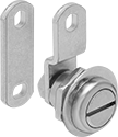
Miniature Slotted-Drive Cam Locks
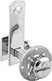
Designed for use in 1/4" or 1/2" dia. through holes. Select the turn direction when mounting the cam.
Style A lock is for use in 1/4" dia. through holes. It doesn't require any tools for installation—insert the shaft through a drilled hole and use the push-on retainer to tension-mount the latch against the inside surface.
Style B locks are for use in 1/2" dia. through holes. They come with a straight cam and a reversible offset cam to accommodate different latching distances.
![]() For technical drawings and 3-D models, click on a part number.
For technical drawings and 3-D models, click on a part number.
Straight Cam | Offset Cam | |||||||||||
|---|---|---|---|---|---|---|---|---|---|---|---|---|
| Style | For Max. Thick. | Latching Distance | For Through Hole Dia. | Head Dia. | Lg. | Wd. | Lg. | Wd. | Mounting Fasteners Included | For Use On | Each | |
Nickel-Plated Steel—Polished | ||||||||||||
| A | 3/4" | 1/4"-1" | 1/4" | 9/16" | 1 5/16" | 1/2" | __ | __ | Yes | Metal, Plastic, Wood | 0000000 | 00000 |
Nickel-Plated Zinc—Dull | ||||||||||||
| B | 5/16" | 9/32", 5/8", 31/32" | 1/2" | 19/32" | 1 1/8" | 3/8" | 1 1/8" | 3/8" | Yes | Metal, Plastic, Wood | 0000000 | 00000 |
Black Powder-Coated Zinc | ||||||||||||
| B | 5/16" | 9/32", 5/8", 31/32" | 1/2" | 19/32" | 1 1/8" | 3/8" | 1 1/8" | 3/8" | Yes | Metal, Plastic, Wood | 0000000 | 00000 |
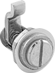
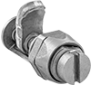
Slotted-Drive Cam Locks
Use this lock in a 3/4" dia. through hole, which is the most common through-hole size. Select the turn direction when mounting the cam. Lock comes with a straight cam and a reversible offset cam to accommodate different latching distances.
![]() For technical drawings and 3-D models, click on a part number.
For technical drawings and 3-D models, click on a part number.
Straight Cam | Offset Cam | ||||||||||
|---|---|---|---|---|---|---|---|---|---|---|---|
| For Max. Thick. | Latching Distance | For Through Hole Dia. | Head Dia. | Lg. | Wd. | Lg. | Wd. | Mounting Fasteners Included | For Use On | Each | |
Nickel-Plated Zinc—Polished | |||||||||||
| 1/4" | 7/16", 5/8", 13/16" | 3/4" | 7/8" | 1 1/2" | 5/8" | 1 1/2" | 5/8" | Yes | Metal, Wood | 00000000 | 00000 |
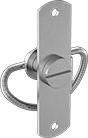
Adjustable-Tension Tight-Hold Slotted-Drive Cam Locks
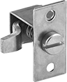
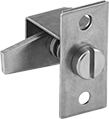
Also known as adjustable compression cam locks, these adjust to compensate for door or drawer misalignment. To latch, turn the head a quarter-turn and then continue to turn it to draw the cam firmly against the door or drawer surface.
For styles A, B, C, D, and F, select the turn direction of the lock when mounting the cam. For styles E and G, turn the lock counterclockwise to open.
Straight Cam | Offset Cam | Mount. Plate | Mount. | Mount. Holes | |||||||||||||||
|---|---|---|---|---|---|---|---|---|---|---|---|---|---|---|---|---|---|---|---|
| Style | For Max. Thick. | Latching Distance | For Through Hole Dia. | Rear Proj. | Head Dia. | Lg. | Wd. | Lg. | Wd. | Wd. | Lg. | Fasteners Included | Screw Size | No. of | Dia. | Ctr.-to-Ctr. | Max. Clamping Force, lbs. | Each | |
Zinc-Plated Steel—Dull | |||||||||||||||||||
Quarter-Turn Clockwise to Open or Quarter-Turn Counterclockwise to Open | |||||||||||||||||||
| B | 3/16" | 1/8"-3/8" | 9/16" | 1" | 1/2" | __ | __ | 3/4" | 1/4" | __ | __ | Yes | __ | __ | __ | __ | 50 | 0000000 | 000000 |
| B | 3/16" | 5/8"-7/8" | 9/16" | 1" | 1/2" | __ | __ | 3/4" | 1/4" | __ | __ | Yes | __ | __ | __ | __ | 50 | 0000000 | 00000 |
| C | 3/16" | 3/8"-5/8" | 9/16" | 1" | 1/2" | 3/4" | 1/4" | __ | __ | __ | __ | Yes | __ | __ | __ | __ | 50 | 0000000 | 00000 |
| D | 3/4" | 1/8"-3/8" | 9/16" | 1 5/16" | 1/2" | __ | __ | 1 5/16" | 5/16" | 7/8" | 1 3/4" | No | No. 10 | 2 | 3/16" | 1 1/4" | 110 | 0000000 | 00000 |
| D | 3/4" | 3/4"-1 1/8" | 9/16" | 1 5/16" | 1/2" | __ | __ | 1 5/16" | 5/16" | 7/8" | 1 3/4" | No | No. 10 | 2 | 3/16" | 1 1/4" | 110 | 0000000 | 00000 |
| F | 3/4" | 3/8"-3/4" | 9/16" | 1 5/16" | 1/2" | 1 5/16" | 5/16" | __ | __ | 7/8" | 1 3/4" | No | No. 10 | 2 | 3/16" | 1 1/4" | 110 | 0000000 | 00000 |
Zinc-Plated Steel—Polished | |||||||||||||||||||
Quarter-Turn Counterclockwise to Open | |||||||||||||||||||
| E | 1/8" | 1/8"-3/4" | 15/16" | 1 3/4" | __ | __ | __ | 1 5/16" | 5/8" | __ | __ | No | No. 10 | 2 | 1/4" | 1 7/8" | 150 | 0000000 | 00000 |
| E | 1/8" | 7/8"-1 11/16" | 15/16" | 1 3/4" | __ | __ | __ | 1 5/16" | 5/8" | __ | __ | No | No. 10 | 2 | 1/4" | 1 7/8" | 150 | 0000000 | 00000 |
| G | 1/8" | 3/8"-1 1/4" | 15/16" | 1 3/4" | __ | 1 5/16" | 5/8" | __ | __ | __ | __ | No | No. 10 | 2 | 1/4" | 1 7/8" | 150 | 0000000 | 00000 |
300 Series Stainless Steel—Dull | |||||||||||||||||||
Quarter-Turn Clockwise to Open or Quarter-Turn Counterclockwise to Open | |||||||||||||||||||
| A | 3/16" | 1/16"-1/4" | 5/16" | 9/16" | 5/16" | __ | __ | 1/2" | 1/4" | __ | __ | Yes | __ | __ | __ | __ | 35 | 0000000 | 00000 |
| D | 3/4" | 1/8"-3/8" | 9/16" | 1 5/16" | 1/2" | __ | __ | 1 5/16" | 5/16" | 7/8" | 1 3/4" | No | No. 10 | 2 | 3/16" | 1 1/4" | 110 | 0000000 | 00000 |
| D | 3/4" | 3/4"-1 1/8" | 9/16" | 1 5/16" | 1/2" | __ | __ | 1 5/16" | 5/16" | 7/8" | 1 3/4" | No | No. 10 | 2 | 3/16" | 1 1/4" | 110 | 0000000 | 00000 |
| F | 3/4" | 3/8"-3/4" | 9/16" | 1 5/16" | 1/2" | 1 5/16" | 5/16" | __ | __ | 7/8" | 1 3/4" | No | No. 10 | 2 | 3/16" | 1 1/4" | 110 | 0000000 | 00000 |
| Latch Covers for Styles D and F | 0000000 | Each | 00000 |
Spring-Cam Slotted-Drive Locks
These locks have a spring-wire cam that slips under a receiving catch on a cabinet body to create tension and hold cabinet doors and drawers closed. To latch, turn the head a quarter-turn to draw the cam against the door or drawer surface. A quarter-turn in the opposite direction releases the tension and opens the door or drawer.
Locks with a serrated-spring cam grip tighter than those with a smooth-spring cam to help retain their hold. They’re best for high-vibration applications.
Fastener-mount locks are easy to remove and replace for maintenance.
Use weld-on locks for a permanent, more secure installation than fastener-mount locks.
Zinc- and copper-plated steel locks are mildly corrosion resistant.
300-series stainless steel locks are more corrosion resistant than zinc- and copper-plated steel locks, so they’re less likely to rust.
![]() For technical drawings and 3-D models, click on a part number.
For technical drawings and 3-D models, click on a part number.
Mounting Plate | Mounting | Mounting Holes | |||||||||||
|---|---|---|---|---|---|---|---|---|---|---|---|---|---|
| For Max. Thick. | Latching Distance | For Through Hole Dia. | Head Dia. | Mount Type | Lg. | Wd. | Fasteners Included | Screw Size | No. of | Ctr.-to-Ctr. | For Use On | Each | |
Copper Plated Steel—Dull | |||||||||||||
Quarter-Turn Counterclockwise to Open | |||||||||||||
| 1/8" | 1/16"-1/8" | 5/16" | 1/4" | Weld On | 1 1/16" | 5/16" | No | __ | 2 | 7/8" | Metal, Plastic, Wood | 0000000 | 00000 |
| 3/16" | 1/16"-1/4" | 7/16" | 3/8" | Weld On | 1 9/16" | 7/16" | No | __ | 2 | 1 5/16" | Metal, Plastic, Wood | 0000000 | 0000 |
| 1/4" | 1/16"-3/8" | 1/2" | 1/2" | Weld On | 2 5/16" | 5/8" | No | __ | 2 | 1 15/16" | Metal, Plastic, Wood | 0000000 | 0000 |
Zinc-Plated Steel—Dull | |||||||||||||
Quarter-Turn Counterclockwise to Open | |||||||||||||
| 1/8" | 1/16"-1/8" | 5/16" | 1/4" | Fastener Mount | 1 1/16" | 5/16" | No | No. 3 | 2 | 7/8" | Metal, Plastic, Wood | 000000 | 0000 |
| 1/4" | 1/16"-1/4" | 7/16" | 3/8" | Fastener Mount | 1 9/16" | 7/16" | No | No. 3 | 2 | 1 5/16" | Metal, Plastic, Wood | 000000 | 0000 |
| 3/8" | 1/16"-3/8" | 1/2" | 1/2" | Fastener Mount | 2 5/16" | 5/8" | No | No. 6 | 2 | 1 15/16" | Metal, Plastic, Wood | 0000000 | 0000 |
| 9/16" | 1/8"-9/16" | 13/16" | 3/4" | Fastener Mount | 3 1/2" | 15/16" | No | No. 10 | 2 | 2 15/16" | Metal, Plastic, Wood | 000000 | 00000 |
300 Series Stainless Steel—Dull | |||||||||||||
Quarter-Turn Counterclockwise to Open | |||||||||||||
| 1/4" | 1/16"-3/8" | 1/2" | 1/2" | Fastener Mount | 2 5/16" | 5/8" | No | No. 6 | 2 | 1 15/16" | Metal, Plastic, Wood | 0000000 | 0000 |
| 1/4" | 1/16"-3/8" | 1/2" | 1/2" | Weld On | 2 5/16" | 5/8" | No | __ | 2 | 1 15/16" | Metal, Plastic, Wood | 0000000 | 0000 |
Mounting Plate | Mounting | Mounting Holes | |||||||||||
|---|---|---|---|---|---|---|---|---|---|---|---|---|---|
| For Max. Thick. | Latching Distance | For Through Hole Dia. | Head Dia. | Mount Type | Lg. | Wd. | Fasteners Included | Screw Size | No. of | Ctr.-to-Ctr. | For Use On | Each | |
Copper Plated Steel—Dull | |||||||||||||
Quarter-Turn Counterclockwise to Open | |||||||||||||
| 1/4" | 1/16"-3/8" | 1/2" | 1/2" | Weld On | 2 5/16" | 5/8" | No | __ | 2 | 1 15/16" | Metal, Plastic, Wood | 0000000 | 00000 |
Zinc-Plated Steel—Dull | |||||||||||||
Quarter-Turn Counterclockwise to Open | |||||||||||||
| 1/4" | 1/16"-3/8" | 1/2" | 1/2" | Fastener Mount | 2 5/16" | 5/8" | No | No. 6 | 2 | 1 15/16" | Metal, Plastic, Wood | 0000000 | 0000 |
| 5/16" | 1/8"-9/16" | 13/16" | 3/4" | Fastener Mount | 3 1/2" | 15/16" | No | No. 10 | 2 | 2 15/16" | Metal, Plastic, Wood | 0000000 | 00000 |
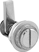
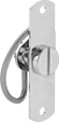
Tight-Hold Slotted-Drive Cam Locks
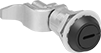
Also known as a compression cam lock, turn the head a quarter-turn to latch, then another quarter-turn to draw the cam firmly against the door or drawer surface. This lock comes with a reversible offset cam to provide variable latching-distance ranges depending on the cam position.
![]() For technical drawings and 3-D models, click on a part number.
For technical drawings and 3-D models, click on a part number.
Latching Distance | Offset Cam | ||||||||||
|---|---|---|---|---|---|---|---|---|---|---|---|
| For Max. Thick. | Short | Long | For Through Hole Dia. | Head Dia. | Lg. | Wd. | Max. Clamping Force, lbs. | Mounting Fasteners Included | For Use On | Each | |
Black Painted Zinc | |||||||||||
Quarter-Turn Counterclockwise to Open | |||||||||||
| 3/4" | 1/2"-1 1/8" | 2 5/8"-3" | 7/8" | 1 1/8" | 1 11/16" | 3/4" | 100 | Yes | Metal, Plastic, Wood | 0000000 | 000000 |