


Default Position Default Position |
|---|
| Closed | P Open to A, B Open to T |
| P Closed, A and B Open to T | P Open to T, A and B Closed |
| P Closed, A Open to T | Open |
| P Open to B, A Open to T |
For Use With For Use With | Show |
|---|
|
For Use With For Use With | Hide |
|---|
Actuation Actuation |
|---|
|
Valve Function Valve Function |
|---|
|
Valve Type Valve Type |
|---|
|
Return Actuation Return Actuation |
|---|
|
Wire Connection Type Wire Connection Type |
|---|
|
Hydraulic Directional Control Valve Flow Pattern Hydraulic DirectionalControl Valve Flow Pattern |
|---|
|
Seal Material Seal Material |
|---|
|
DFARS (Defense Acquisition Regulations Supplement) DFARS (Defense AcquisitionRegulations Supplement) |
|---|
Electrical Connection Type Electrical Connection Type |
|---|
|
RoHS (Restriction of Hazardous Substances) RoHS (Restriction ofHazardous Substances) |
|---|
|
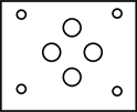
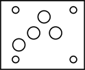
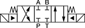
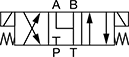
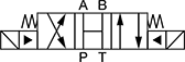
Solenoid-Operated Directional-Control Block-Mount Hydraulic Valves
Direct flow with an electronic signal. Use screws to attach to an NFPA valve-mounting block (each component sold separately).
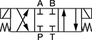
In NFPA diagrams, P represents the pressure source, T represents the tank, and A and B represent work ports.
![]() For technical drawings and 3-D models, click on a part number.
For technical drawings and 3-D models, click on a part number.


Valves | Screws | |||||||||
|---|---|---|---|---|---|---|---|---|---|---|
| NFPA Mounting Pattern | ISO Trade Size | Max. Flow Rate, gpm | Max. Pressure, psi | Choose a Voltage | Each | Pkg. Qty. | Pkg. | |||
Default Position: P Open to A, B Open to T | ||||||||||
| 1 | D03 | 3 | 20 | 5,000 | 00000000 | 0000000 | 4 | 0000000 | 00000 | |
| 1 | D05 | 5 | 40 | 5,000 | 00000000 | 000000 | 4 | 0000000 | 0000 | |
Default Position: P Open to B, A Open to T | ||||||||||
| 2 | D03 | 3 | 20 | 5,000 | 00000000 | 000000 | 4 | 0000000 | 0000 | |
| 2 | D05 | 5 | 40 | 5,000 | 00000000 | 000000 | 4 | 0000000 | 0000 | |
Valves | Screws | |||||||||
|---|---|---|---|---|---|---|---|---|---|---|
| NFPA Mounting Pattern | ISO Trade Size | Max. Flow Rate, gpm | Max. Pressure, psi | Choose a Voltage | Each | Pkg. Qty. | Pkg. | |||
Default Position: Closed | ||||||||||
| 3 | D03 | 3 | 20 | 5,000 | 0000000 | 0000000 | 4 | 0000000 | 00000 | |
| 3 | D05 | 5 | 40 | 5,000 | 0000000 | 000000 | 4 | 0000000 | 0000 | |
| 4 | D08 | 8 | 100 | 5,000 | 00000000 | 00000000 | 6 | 0000000 | 00000 | |
Default Position: Open | ||||||||||
| 5 | D03 | 3 | 20 | 5,000 | 0000000 | 000000 | 4 | 0000000 | 0000 | |
| 5 | D05 | 5 | 40 | 5,000 | 00000000 | 000000 | 4 | 0000000 | 0000 | |
| 6 | D08 | 8 | 80 | 5,000 | 00000000 | 00000000 | 6 | 0000000 | 00000 | |
Default Position: P Closed, A and B Open to T | ||||||||||
| 7 | D03 | 3 | 10 | 5,000 | 0000000 | 000000 | 4 | 0000000 | 0000 | |
| 7 | D05 | 5 | 40 | 5,000 | 00000000 | 000000 | 4 | 0000000 | 0000 | |
| 8 | D08 | 8 | 100 | 5,000 | 00000000 | 00000000 | 6 | 0000000 | 00000 | |
Default Position: P Open to T, A and B Closed | ||||||||||
| 9 | D03 | 3 | 15 | 5,000 | 0000000 | 000000 | 4 | 0000000 | 0000 | |
| 9 | D05 | 5 | 10 | 5,000 | 00000000 | 000000 | 4 | 0000000 | 0000 | |
| 10 | D08 | 8 | 100 | 5,000 | 00000000 | 00000000 | 6 | 0000000 | 00000 | |
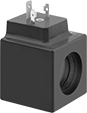
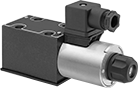
Solenoid-Operated On/Off Screw-In Hydraulic Valves
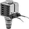
Start and stop flow with an electronic signal. A spring returns the valve to its default position when the signal stops. Also known as cartridge valves, these compact valves screw into your mounting block.
![]() For technical drawings and 3-D models, click on a part number.
For technical drawings and 3-D models, click on a part number.
Valves | ||||||||||||
|---|---|---|---|---|---|---|---|---|---|---|---|---|
Body— UN/UNF (SAE Straight) | Repl. Solenoid Coils | |||||||||||
| Deltrol Equivalent Model No. | Hydraforce Equivalent Model No. | Parker Equivalent Model No. | Thread Size | Dash Size | Max. Flow Rate, gpm | Max. Pressure, psi | Voltage | O'all Ht. | Each | Each | ||
Single-Solenoid | ||||||||||||
| DSV2-080-2NCS-N-D1DE | SV08-24-0-N-12EL | DSL082-C-N-SP-D012-L | 3/4"-16 | 08 | 3 | 3,000 | 12V DC | 5 5/8" | 0000000 | 000000 | 0000000 | 000000 |
| DSV2-080-2NCS-N-D2DE | SV08-24-0-N-24EL | DSL082-C-N-SP-D012-L | 3/4"-16 | 08 | 3 | 3,000 | 24V DC | 5 5/8" | 0000000 | 00000 | 0000000 | 00000 |
| DSV2-080-2NOS-N-D1DE | SV08-25-0-N-12EL | DSL082-N-N-SP-D012-L | 3/4"-16 | 08 | 3 | 3,000 | 12V DC | 3 7/8" | 0000000 | 00000 | 0000000 | 00000 |
| DSV2-080-2NOS-N-D2DE | SV08-25-0-N-24EL | DSL082-N-N-SP-D012-L | 3/4"-16 | 08 | 3 | 3,000 | 24V DC | 3 7/8" | 0000000 | 00000 | 0000000 | 00000 |
| DSV2-100-2NCS-N-D1D | SV10-24-0-N-12DL | DSV102-C-N-D012-L | 7/8"-14 | 10 | 6 | 3,000 | 12V DC | 4 5/8" | 0000000 | 00000 | 0000000 | 00000 |
| DSV2-100-2NOS-N-D1DE | SV10-25-0-N-12DL | DSV102-N-N-D012-L | 7/8"-14 | 10 | 6 | 3,000 | 12V DC | 4 5/8" | 0000000 | 00000 | 0000000 | 00000 |
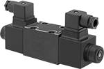
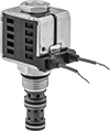
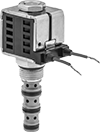
Directional-Control Screw-In Hydraulic Valves
Control the direction of flow or stop flow altogether with an electronic signal. These valves are also known as cartridge valves, and they screw into your mounting block.
Place three-way valves between the pressure source and a single-acting cylinder. Place four-way valves between the pressure source and a double-acting cylinder.
In NFPA diagrams, P represents the pressure source, T represents the tank, and A and B represent work ports.
![]() For technical drawings and 3-D models, click on a part number.
For technical drawings and 3-D models, click on a part number.

Valves | ||||||||||||
|---|---|---|---|---|---|---|---|---|---|---|---|---|
Body— UN/UNF (SAE Straight) | Repl. Solenoid Coils | |||||||||||
| Deltrol Equivalent Model No. | Hydraforce Equivalent Model No. | Parker Equivalent Model No. | Thread Size | Dash Size | Max. Flow Rate, gpm | Max. Pressure, psi | Voltage | O'all Ht. | Each | Each | ||
Style 1—Default Position: P Closed, A Open to T | ||||||||||||
| DSV2-080-3B-N-D1DE | SV08-30-0-N-12EL | DSL083-B-N-SP-D012-L | 3/4"-16 | 08 | 5 | 3,000 | 12V DC | 4 3/8" | 0000000 | 000000 | 0000000 | 000000 |
| DSV2-080-3B-N-D2DE | SV08-30-0-N-24EL | DSL083-B-N-SP-D024-L | 3/4"-16 | 08 | 5 | 3,000 | 24V DC | 4 3/8" | 0000000 | 00000 | 0000000 | 00000 |
| DSV2-100-3B-N-D1D | __ | DSL103-B-N-D012-L | 7/8"-14 | 10 | 6 | 3,000 | 12V DC | 4 1/4" | 0000000 | 000000 | 0000000 | 00000 |


Valves | ||||||||||||
|---|---|---|---|---|---|---|---|---|---|---|---|---|
Body— UN/UNF (SAE Straight) | Repl. Solenoid Coils | |||||||||||
| Deltrol Equivalent Model No. | Hydraforce Equivalent Model No. | Parker Equivalent Model No. | Thread Size | Dash Size | Max. Flow Rate, gpm | Max. Pressure, psi | Voltage | O'all Ht. | Each | Each | ||
Style 2—Default Position: Closed | ||||||||||||
| DSV2-080-4NC-N-D1DE | SV08-41-0-N-12EL | DSL084-N-N-DP-D012-L | 3/4"-16 | 08 | 3 | 3,000 | 12V DC | 5" | 0000000 | 000000 | 0000000 | 000000 |
| DSV2-080-4NC-N-D2DE | SV08-41-0-N-24EL | DSL084-N-N-DP-D024-L | 3/4"-16 | 08 | 3 | 3,000 | 24V DC | 5" | 0000000 | 00000 | 0000000 | 00000 |
Style 3—Default Position: P Open to A, B Open to T | ||||||||||||
| DSV2-080-4CO-N-D1DE | SV08-40-0-N-12EL | DSL084-B-N-SP-D012-L | 3/4"-16 | 08 | 3 | 3,000 | 12V DC | 5" | 0000000 | 00000 | 0000000 | 00000 |
| DSV2-080-4CO-N-D2DE | SV08-40-0-N-24EL | DSL084-B-N-SP-D024-L | 3/4"-16 | 08 | 3 | 3,000 | 24V DC | 5" | 0000000 | 00000 | 0000000 | 00000 |
| DSV2-100-4CO-N-D1D | SV10-40-0-N-12DL | DSL104-B-N-D012-L | 7/8"-14 | 10 | 6 | 3,000 | 12V DC | 4 7/8" | 0000000 | 000000 | 0000000 | 00000 |
Style 4—Default Position: P Open to T, A and B Closed | ||||||||||||
| DSV2-080-4TC-N-D2DE | __ | __ | 3/4"-16 | 08 | 3 | 3,000 | 24V DC | 5" | 0000000 | 00000 | 0000000 | 00000 |
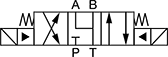
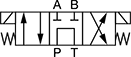
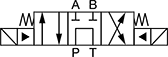
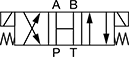
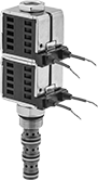 Double-Solenoid Four-Way Valve | 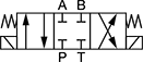 5 | 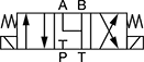 7 |
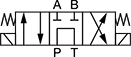 8 | 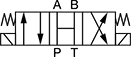 6 |
Valves | ||||||||||||
|---|---|---|---|---|---|---|---|---|---|---|---|---|
Body— UN/UNF (SAE Straight) | Repl. Solenoid Coils | |||||||||||
| Deltrol Equivalent Model No. | Hydraforce Equivalent Model No. | Parker Equivalent Model No. | Thread Size | Dash Size | Max. Flow Rate, gpm | Max. Pressure, psi | Voltage | O'all Ht. | Each | Each | ||
Style 5—Default Position: Closed | ||||||||||||
| DSV-080-34C-N-D1DE | SV08-47C-0-N-12EL | __ | 3/4"-16 | 08 | 3 | 3,000 | 12V DC | 7 3/8" | 0000000 | 0000000 | 0000000 | 000000 |
| DSV-080-34C-N-D2DE | SV08-47C-0-N-24EL | __ | 3/4"-16 | 08 | 3 | 3,000 | 24V DC | 7 3/8" | 0000000 | 000000 | 0000000 | 00000 |
| DSV-100-34C-N-D1D | SV10-47C-0-N-12DL | DSL105-C1-N-D012-L | 7/8"-14 | 10 | 6 | 3,000 | 12V DC | 7" | 0000000 | 000000 | 0000000 | 00000 |
Style 6—Default Position: Open | ||||||||||||
| DSV-080-34O-N-D1DE | SV08-47B-0-N-12ER | __ | 3/4"-16 | 08 | 1.5 | 3,000 | 12V DC | 7 3/8" | 0000000 | 000000 | 0000000 | 00000 |
| DSV-080-34O-N-D2DE | SV08-47B-0-N-24ER | __ | 3/4"-16 | 08 | 1.5 | 3,000 | 24V DC | 7 3/8" | 0000000 | 000000 | 0000000 | 00000 |
| DSV-100-34O-N-D1D | SV10-47B-0-N-12DL | DSL105-C2-N-D012-L | 7/8"-14 | 10 | 3 | 3,000 | 12V DC | 7" | 0000000 | 000000 | 0000000 | 00000 |
Style 7—Default Position: P Closed, A and B Open to T | ||||||||||||
| DSV-080-34M-N-D1DE | SV08-47D-0-N-12EL | __ | 3/4"-16 | 08 | 3 | 3,000 | 12V DC | 7 3/8" | 0000000 | 000000 | 0000000 | 00000 |
| DSV-080-34M-N-D2DE | SV08-47D-0-N-24EL | __ | 3/4"-16 | 08 | 3 | 3,000 | 24V DC | 7 3/8" | 0000000 | 000000 | 0000000 | 00000 |
| DSV-100-34M-N-D1D | SV10-47D-0-N-12DL | DSL105-C4-N-D012-L | 7/8"-14 | 10 | 6 | 3,000 | 12V DC | 7" | 0000000 | 000000 | 0000000 | 00000 |
Style 8—Default Position: P Open to T, A and B Closed | ||||||||||||
| DSV-080-34T-N-D1DE | SV08-47A-0-N-12EL | __ | 3/4"-16 | 08 | 3 | 3,000 | 12V DC | 7 3/8" | 0000000 | 000000 | 0000000 | 00000 |
| DSV-080-34T-N-D2DE | SV08-47A-0-N-24EL | __ | 3/4"-16 | 08 | 3 | 3,000 | 24V DC | 7 3/8" | 0000000 | 000000 | 0000000 | 00000 |
| DSV-100-34T-N-D1D | SV10-47A-0-N-12DL | DSL105-C9-N-D012-L | 7/8"-14 | 10 | 4 | 3,000 | 12V DC | 7" | 0000000 | 000000 | 0000000 | 00000 |