


Thread Type Thread Type |
|---|
Body Material Body Material |
|---|
|
Maximum Pressure Maximum Pressure |
|---|
|
Valve Starting Position Valve Starting Position |
|---|
|
Valve Type Valve Type |
|---|
|
For Use With For Use With | Show |
|---|
|
For Use With For Use With | Hide |
|---|
Wire Connection Type Wire Connection Type |
|---|
|
Actuation Actuation |
|---|
--30402310031599830276-p9@1x_637354092326867916.png?ver=imagenotfound) | Electric (Solenoid) |
Valve Function Valve Function |
|---|
|
Shape Shape |
|---|
| Straight | |
Pressure Drop Pressure Drop |
|---|
|
Maximum Temperature Maximum Temperature |
|---|
|
Minimum Temperature Minimum Temperature |
|---|
|
Connection Style Connection Style |
|---|
 | Threaded |
Connection Type Connection Type |
|---|
| Pipe | |
Mounting Orientation Mounting Orientation |
|---|
|
RoHS (Restriction of Hazardous Substances) RoHS (Restriction ofHazardous Substances) |
|---|
|
REACH (Registration, Evaluation, Authorization and Restriction of Chemicals) REACH (Registration,Evaluation, Authorization and Restriction of Chemicals) |
|---|
|
About Actuated On/Off Valves
More
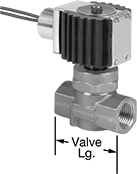
Solenoid On/Off Valves for Coolant and Detergent
These valves operate on electricity to automatically start and stop flow. The actuator is directly mounted to the valve body to minimize movement and reduce wear.
Normally closed valves are closed unless actuated. 304 stainless steel valves are more corrosion resistant than nickel-plated and plain brass valves. 316 stainless steel valves have excellent corrosion resistance.
Zero pressure drop valves don’t require a minimum pressure drop between the inlet and outlet for operation. Pressure drop assisted valves require a minimum pressure drop between the inlet and the outlet for operation; the upstream pressure must be greater than the downstream pressure.
For valves rated NEMA 2 and IP50, the ratings apply only to the enclosure, which resists water and dust.
Flow coefficient (Cv) is the amount of water (in gallons per minute) at 60° F that will flow through a fully open valve with a difference of 1 psi between the inlet and the outlet.
![]() For technical drawings and 3-D models, click on a part number.
For technical drawings and 3-D models, click on a part number.
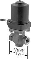
- For Use With: Ethylene Glycol, Soap Solutions
Valves | Replacement Copper Solenoid Coils | |||||||||||
|---|---|---|---|---|---|---|---|---|---|---|---|---|
| Pipe Size | Gender | Thread Type | Flow Coefficient (Cv) | Max. Pressure | Pressure Drop | Temp. Range, °F | Valve Lg. | O'all Ht. | Each | Each | ||
Normally Closed—120V AC | ||||||||||||
| 1/2 | Female | NPT | 4 | 110 psi @ 400° F | Zero Pressure Drop | -320° to 400° | 3 1/4" | 7 3/16" | 0000000 | 0000000 | 0000000 | 0000000 |
| 1/2 | Female | NPT | 4 | 200 psi @ 400° F | Zero Pressure Drop | -320° to 400° | 3 1/4" | 7 3/16" | 0000000 | 000000 | 0000000 | 000000 |
| 1/2 | Female | NPT | 4 | 300 psi @ 400° F | Zero Pressure Drop | -320° to 400° | 3 1/4" | 8" | 0000000 | 000000 | 0000000 | 000000 |
| 3/4 | Female | NPT | 8 | 110 psi @ 400° F | Zero Pressure Drop | -320° to 400° | 3 1/2" | 7 5/16" | 0000000 | 000000 | 0000000 | 000000 |
| 1 | Female | NPT | 13 | 110 psi @ 400° F | Zero Pressure Drop | -320° to 400° | 4 1/8" | 8" | 0000000 | 000000 | 0000000 | 000000 |
| 1 | Female | NPT | 13 | 200 psi @ 400° F | Zero Pressure Drop | -320° to 400° | 4 1/8" | 8 7/8" | 0000000 | 000000 | 0000000 | 000000 |
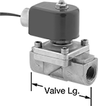
- For Use With: Ethylene Glycol, Soap Solutions
- Specifications Met: CSA Certified, UL Listed
| Pipe Size | Gender | Thread Type | Max. Pressure | Pressure Drop | Temp. Range, °F | Valve Lg. | O'all Ht. | Environmental Rating | Each | |
Normally Closed—120V AC | ||||||||||
|---|---|---|---|---|---|---|---|---|---|---|
| 3/8 | Female | NPT | 150 psi @ 70° F | Zero Pressure Drop | 0° to 300° | 3 1/2" | 4 1/8" | IP50, NEMA 2 | 00000000 | 0000000 |
| 1/2 | Female | NPT | 150 psi @ 70° F | Zero Pressure Drop | 0° to 300° | 3 1/2" | 4 1/8" | IP50, NEMA 2 | 00000000 | 00000000 |
| 3/4 | Female | NPT | 150 psi @ 70° F | Zero Pressure Drop | 0° to 300° | 3 1/2" | 4 1/8" | IP50, NEMA 2 | 00000000 | 00000000 |
| 1 | Female | NPT | 150 psi @ 70° F | Zero Pressure Drop | 0° to 300° | 3 1/2" | 4 7/16" | IP50, NEMA 2 | 00000000 | 000000 |
- For Use With: Ethylene Glycol, Soap Solutions
| Pipe Size | Gender | Thread Type | Flow Coefficient (Cv) | Max. Pressure | Pressure Drop | Temp. Range, °F | Valve Lg. | O'all Ht. | Each | |
Normally Closed—120V AC | ||||||||||
|---|---|---|---|---|---|---|---|---|---|---|
| 1/2 | Female | NPT | 3 | 1000 psi @ 300° F | Pressure Drop Assisted | -40° to 300° | 3 1/8" | 6 3/4" | 0000000 | 0000000 |
| 1 | Female | NPT | 6 | 1000 psi @ 300° F | Pressure Drop Assisted | -40° to 300° | 4 3/16" | 7 7/16" | 0000000 | 00000000 |
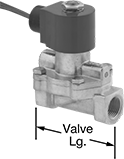
Solenoid On/Off Valves with Easy-Access Strainer for Detergent
- For Use With: Soap Solutions
- Seal Material: EPDM Rubber
A built-in strainer traps debris and allows you to replace the screen without disconnecting your pipeline. These valves operate on electricity to automatically start and stop flow.
All valves are normally closed unless actuated. They require a minimum pressure drop between the inlet and the outlet for operation; the upstream pressure must be greater than the downstream pressure. The actuator is directly mounted to the valve body to minimize movement and reduce wear.
Flow coefficient (Cv) is the amount of water (in gallons per minute) at 60° F that will flow through a fully open valve with a difference of 1 psi between the inlet and the outlet.
![]() For technical drawings and 3-D models, click on a part number.
For technical drawings and 3-D models, click on a part number.
| Pipe Size | Gender | Thread Type | Flow Coefficient (Cv) | Max. Pressure | Pressure Drop | Temp. Range, °F | Valve Lg. | O'all Ht. | Mesh Size | Quick-Disconnect Tab Wd. | Each | |
Brass Body with Quick-Disconnect Terminals | ||||||||||||
|---|---|---|---|---|---|---|---|---|---|---|---|---|
Normally Closed—24V AC | ||||||||||||
| 1/4 | Female | NPT | 1 | 125 psi @ 180° F | Pressure Drop Assisted | 35° to 180° | 2 3/8" | 3 3/4" | 60 × 60 | 1/4" | 0000000 | 000000 |
| 3/8 | Female | NPT | 1 | 125 psi @ 180° F | Pressure Drop Assisted | 35° to 180° | 2 3/8" | 3 3/4" | 60 × 60 | 1/4" | 0000000 | 00000 |
Normally Closed—24V DC | ||||||||||||
| 1/4 | Female | NPT | 1 | 125 psi @ 180° F | Pressure Drop Assisted | 35° to 180° | 2 3/8" | 3 3/4" | 60 × 60 | 1/4" | 0000000 | 00000 |
| 3/8 | Female | NPT | 1 | 125 psi @ 180° F | Pressure Drop Assisted | 35° to 180° | 2 3/8" | 3 3/4" | 60 × 60 | 1/4" | 0000000 | 00000 |
Normally Closed—120V AC | ||||||||||||
| 1/4 | Female | NPT | 1 | 125 psi @ 180° F | Pressure Drop Assisted | 35° to 180° | 2 3/8" | 3 3/4" | 60 × 60 | 1/4" | 0000000 | 00000 |
| 3/8 | Female | NPT | 1 | 125 psi @ 180° F | Pressure Drop Assisted | 35° to 180° | 2 3/8" | 3 3/4" | 60 × 60 | 1/4" | 0000000 | 00000 |
Normally Closed—240V AC | ||||||||||||
| 1/4 | Female | NPT | 1 | 125 psi @ 180° F | Pressure Drop Assisted | 35° to 180° | 2 3/8" | 3 3/4" | 60 × 60 | 1/4" | 0000000 | 00000 |
| 3/8 | Female | NPT | 1 | 125 psi @ 180° F | Pressure Drop Assisted | 35° to 180° | 2 3/8" | 3 3/4" | 60 × 60 | 1/4" | 0000000 | 00000 |
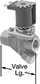
High-Use Solenoid On/Off Valves for Detergent
- For Use With: Soap Solutions
- Seal Material: PTFE Plastic
- Specifications Met: C-UL Listed, UL Listed
Sturdy internal components resist wear for a long service life in applications with frequent cycling. These valves operate on electricity to automatically start and stop flow.
All valves are normally closed unless actuated. They require a minimum pressure drop between the inlet and the outlet for operation; the upstream pressure must be greater than the downstream pressure. The actuator is directly mounted to the valve body to minimize movement and reduce wear.
Flow coefficient (Cv) is the amount of water (in gallons per minute) at 60° F that will flow through a fully open valve with a difference of 1 psi between the inlet and the outlet.
![]() For technical drawings and 3-D models, click on a part number.
For technical drawings and 3-D models, click on a part number.
| Pipe Size | Gender | Thread Type | Flow Coefficient (Cv) | Max. Pressure | Pressure Drop | Temp. Range, °F | Valve Lg. | O'all Ht. | Each | |
Brass Body with Wire Leads | ||||||||||
|---|---|---|---|---|---|---|---|---|---|---|
Normally Closed—120V AC | ||||||||||
| 3/8 | Female | NPT | 2 | 150 psi @ 180° F | Pressure Drop Assisted | 35° to 200° | 2 1/16" | 3 3/4" | 0000000 | 0000000 |
| 1/2 | Female | NPT | 3 | 150 psi @ 180° F | Pressure Drop Assisted | 35° to 200° | 2 3/8" | 3 7/8" | 0000000 | 000000 |
| 3/4 | Female | NPT | 5 | 150 psi @ 180° F | Pressure Drop Assisted | 35° to 200° | 3" | 4 1/4" | 0000000 | 000000 |
| 1 | Female | NPT | 8 | 150 psi @ 180° F | Pressure Drop Assisted | 35° to 200° | 3 1/2" | 4 3/4" | 0000000 | 000000 |