


Filter by


Face Material
Maximum Spring Force
Body Material
Minimum Spring Force
Export Control Classification Number (ECCN)
DFARS Specialty Metals
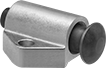
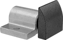
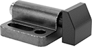
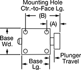
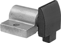
Spring-Loaded Guide Plungers
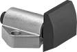
Round Face
 |  |  |
Triangular Base | Rectangular Base |
Round face plungers hold curved and contoured surfaces.
Acetal Face—An acetal face is nonmarring to protect soft metal and polished surfaces.
Steel Face—A steel face is strong and wear resistant.
Stainless Steel Face—Choose a stainless steel face for chemical and corrosion resistance.
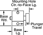
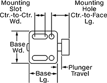
Base | Mounting Hole | ||||||||||||||
|---|---|---|---|---|---|---|---|---|---|---|---|---|---|---|---|
Face Dia. | Plunger Travel | Shape | Lg. | Wd. | Spring Force, lbf | Body Material | No. of | Dia. | Ctr.-to-Ctr. Wd. | Ctr.-to-Face Lg. | Mounting Fasteners Included | Each | |||
Acetal Face | |||||||||||||||
| 0.38" | 1/8" | Triangle | 0.688" | 0.875" | 1.5 to 2.5 | Aluminum | 2 | 0.138" | 0.656" | 0.593" | No | 3351A43 | 00000 | ||
| 0.38" | 1/8" | Triangle | 0.688" | 0.875" | 5.1 to 14.6 | Aluminum | 2 | 0.136" | 0.656" | 0.593" | No | 3351A36 | 0000 | ||
| 0.56" | 3/16" | Rectangle | 1" | 1.5" | 2.3 to 25.8 | Aluminum | 2 | 0.203" | 1.125" | 0.875" | No | 3351A37 | 0000 | ||
| 0.81" | 1/4" | Rectangle | 1.375" | 2" | 16.5 to 47.5 | Aluminum | 2 | 0.266" | 1.5" | 1.218" | No | 3351A38 | 00000 | ||
Steel Face | |||||||||||||||
| 0.38" | 1/8" | Triangle | 0.688" | 0.875" | 1.5 to 2.5 | Aluminum | 2 | 0.138" | 0.656" | 0.593" | No | 3351A41 | 0000 | ||
| 0.38" | 1/8" | Triangle | 0.688" | 0.875" | 5.1 to 14.6 | Aluminum | 2 | 0.136" | 0.656" | 0.593" | No | 3351A11 | 0000 | ||
| 0.56" | 3/16" | Rectangle | 1" | 1.5" | 2.3 to 25.8 | Aluminum | 2 | 0.203" | 1.125" | 0.875" | No | 3351A14 | 0000 | ||
| 0.81" | 1/4" | Rectangle | 1.375" | 2" | 16.5 to 47.5 | Aluminum | 2 | 0.266" | 1.5" | 1.218" | No | 3351A17 | 00000 | ||
Stainless Steel Face | |||||||||||||||
| 0.38" | 1/8" | Triangle | 0.688" | 0.875" | 1.5 to 2.5 | Aluminum | 2 | 0.138" | 0.656" | 0.593" | No | 3351A42 | 00000 | ||
| 0.38" | 1/8" | Triangle | 0.688" | 0.875" | 5.1 to 14.6 | Aluminum | 2 | 0.138" | 0.656" | 0.593" | No | 3351A44 | 00000 | ||
| 0.56" | 3/16" | Triangle | 1" | 1.5" | 2.3 to 25.8 | Aluminum | 2 | 0.19" | 1.125" | 0.875" | No | 3351A45 | 00000 | ||
| 0.81" | 1/4" | Triangle | 1.375" | 2" | 16.5 to 47.5 | Aluminum | 2 | 0.25" | 1.5" | 1.218" | No | 3351A46 | 00000 | ||
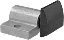
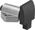
Square Face
 |  |  |
Triangular Base | Rectangular Base | Rectangular Base 2 Mounting Slots |
 |  |  |
2 Mounting Slots 2 Mounting Holes | 2 Mounting Holes | 4 Mounting Holes |
Base | Mounting Slot | Mounting Hole | ||||||||||||||||||
|---|---|---|---|---|---|---|---|---|---|---|---|---|---|---|---|---|---|---|---|---|
Face Wd. | Plunger Travel | Shape | Lg. | Wd. | Spring Force, lbf | Body Material | No. of | Lg. | Wd. | Ctr.-to-Ctr. Wd. | No. of | Dia. | Ctr.-to-Ctr. Wd. | Ctr.-to-Ctr. Lg. | Ctr.-to-Face Lg. | Mounting Fasteners Included | Each | |||
Acetal Face—Adjustable | ||||||||||||||||||||
| 0.39" | 1/8" | Rectangle | 0.65" | 0.866" | 1.8 to 2.4 | Zinc Alloy | 2 | 0.307" | 0.13" | 0.551" | 2 | 0.13" | 0.551" | — | 0.457" | No | 3351A111 | 00000 | ||
| 0.39" | 1/8" | Rectangle | 0.65" | 0.866" | 2.5 to 4.5 | Zinc Alloy | 2 | 0.307" | 0.13" | 0.551" | 2 | 0.13" | 0.551" | — | 0.457" | No | 3351A112 | 0000 | ||
| 0.63" | 3/16" | Rectangle | 1.083" | 1.25" | 1.8 to 4.2 | Zinc Alloy | 2 | 0.606" | 0.213" | 0.827" | 2 | 0.213" | 0.827" | — | 0.689" | No | 3351A115 | 00000 | ||
| 0.63" | 3/16" | Rectangle | 1.083" | 1.25" | 4.3 to 10.1 | Zinc Alloy | 2 | 0.606" | 0.213" | 0.827" | 2 | 0.213" | 0.827" | — | 0.689" | No | 3351A116 | 00000 | ||
| 0.87" | 5/16" | Rectangle | 1.375" | 1.5" | 3.9 to 7.4 | Zinc Alloy | 2 | 0.787" | 0.25" | 1.063" | 2 | 0.25" | 1.063" | — | 0.972" | No | 3351A119 | 00000 | ||
| 0.87" | 5/16" | Rectangle | 1.375" | 1.5" | 6.1 to 16.8 | Zinc Alloy | 2 | 0.787" | 0.25" | 1.063" | 2 | 0.25" | 1.063" | — | 0.972" | No | 3351A121 | 00000 | ||
Steel Face | ||||||||||||||||||||
| 0.63" | 1/8" | Triangle | 0.688" | 0.875" | 5.1 to 14.6 | Aluminum | — | — | — | — | 2 | 0.136" | 0.656" | — | 0.656" | No | 3351A13 | 0000 | ||
| 0.88" | 3/16" | Rectangle | 1" | 1.5" | 2.3 to 25.8 | Aluminum | — | — | — | — | 2 | 0.203" | 1.125" | — | 0.983" | No | 3351A16 | 0000 | ||
| 1.25" | 1/4" | Rectangle | 1.375" | 2" | 16.5 to 47.5 | Aluminum | — | — | — | — | 2 | 0.266" | 1.5" | — | 1.312" | No | 3351A19 | 00000 | ||
| 1.75" | 1/4" | Rectangle | 2.25" | 1.75" | 50 to 160 | Steel | — | — | — | — | 4 | 0.25" | 1.38" | 1.75" | 1" (A), 2.75" (B) | No | 3351A47 | 000000 | ||
Stainless Steel Face—Adjustable | ||||||||||||||||||||
| 0.39" | 1/8" | Rectangle | 0.65" | 0.866" | 1.8 to 2.4 | Zinc Alloy | 2 | 0.307" | 0.13" | 0.551" | 2 | 0.13" | 0.551" | — | 0.457" | No | 3351A113 | 00000 | ||
| 0.39" | 1/8" | Rectangle | 0.65" | 0.866" | 2.5 to 4.5 | Zinc Alloy | 2 | 0.307" | 0.13" | 0.551" | 2 | 0.13" | 0.551" | — | 0.457" | No | 3351A114 | 00000 | ||
| 0.63" | 3/16" | Rectangle | 1.083" | 1.25" | 1.8 to 4.2 | Zinc Alloy | 2 | 0.606" | 0.213" | 0.827" | 2 | 0.213" | 0.827" | — | 0.689" | No | 3351A117 | 00000 | ||
| 0.63" | 3/16" | Rectangle | 1.083" | 1.25" | 4.3 to 10.1 | Zinc Alloy | 2 | 0.606" | 0.213" | 0.827" | 2 | 0.213" | 0.827" | — | 0.689" | No | 3351A118 | 00000 | ||
| 0.87" | 5/16" | Rectangle | 1.375" | 1.5" | 3.9 to 7.4 | Zinc Alloy | 2 | 0.787" | 0.25" | 1.063" | 2 | 0.25" | 1.063" | — | 0.972" | No | 3351A122 | 00000 | ||
| 0.87" | 5/16" | Rectangle | 1.375" | 1.5" | 6.1 to 16.8 | Zinc Alloy | 2 | 0.787" | 0.25" | 1.063" | 2 | 0.25" | 1.063" | — | 0.972" | No | 3351A123 | 00000 | ||
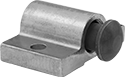
Square Face with Chamfered Bottom
 |  | |
Triangular Base | Rectangular Base |
Plungers that have a square face with chamfered bottom provide extra clearance for weld beads or imperfections on your workpiece.
Steel Face—A steel face is strong and wear resistant.
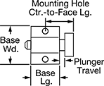
Base | Mounting Hole | ||||||||||||||
|---|---|---|---|---|---|---|---|---|---|---|---|---|---|---|---|
Face Wd. | Plunger Travel | Shape | Lg. | Wd. | Spring Force, lbf | Body Material | No. of | Dia. | Ctr.-to-Ctr. Wd. | Ctr.-to-Face Lg. | Mounting Fasteners Included | Each | |||
Steel Face | |||||||||||||||
| 0.63" | 1/8" | Triangle | 0.688" | 0.875" | 5.1 to 14.6 | Aluminum | 2 | 0.136" | 0.656" | 0.656" | No | 3351A21 | 000000 | ||
| 0.88" | 3/16" | Rectangle | 1" | 1.5" | 2.3 to 25.8 | Aluminum | 2 | 0.203" | 1.125" | 0.983" | No | 3351A22 | 00000 | ||
| 1.25" | 1/4" | Rectangle | 1.375" | 2" | 16.5 to 47.5 | Aluminum | 2 | 0.266" | 1.5" | 1.312" | No | 3351A23 | 00000 | ||
Spring-Loaded Guide Plungers for Thin Workpieces
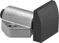
Square Face with Tang
 |  | |
Triangular Base | Rectangular Base |
Base | Mounting Hole | ||||||||||||||
|---|---|---|---|---|---|---|---|---|---|---|---|---|---|---|---|
Face Wd. | Plunger Travel | Shape | Lg. | Wd. | Spring Force, lbf | Body Material | No. of | Dia. | Ctr.-to-Ctr. | Ctr.-to-Face Lg. | Mounting Fasteners Included | Each | |||
Steel Face | |||||||||||||||
| 0.63" | 1/8" | Triangle | 0.688" | 0.875" | 5.1 to 14.6 | Aluminum | 2 | 0.136" | 0.656" | 0.656" | No | 3351A12 | 00000 | ||
| 0.88" | 3/16" | Rectangle | 1" | 1.5" | 2.3 to 25.8 | Aluminum | 2 | 0.203" | 1.125" | 0.983" | No | 3351A15 | 0000 | ||
| 1.25" | 1/4" | Rectangle | 1.375" | 2" | 16.5 to 47.5 | Aluminum | 2 | 0.266" | 1.5" | 1.312" | No | 3351A18 | 00000 | ||
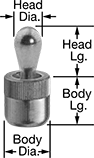
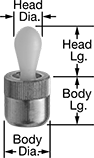
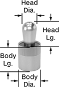
Spring Locating Pins
 |  |
Zinc-Plated Steel Head | Acetal Head |
As the workpiece pushes against the pin head in one direction, the internal spring pushes back to hold it in place for clamping. Press into a drilled hole using the installation tool (sold separately). Also known as spring locating pins and side-thrust pins.
Acetal Head—Acetal-head pins won't mar soft metal and polished surfaces.
Pins | Installation Tools | |||||||||||||
|---|---|---|---|---|---|---|---|---|---|---|---|---|---|---|
Body | Head | |||||||||||||
Dia. | Lg. | Dia. | Lg. | Max. Head Movement | Min. Spring Force | Max. Spring Force, lbf | Body Dia. Tolerance | Body Material | Each | Each | ||||
Zinc-Plated Steel Head | ||||||||||||||
| 0.25" | 0.28" | 0.12" | 0.16" | 0.04" | 2.3 lbf | 2.5 | 0" to 0.0009" | Aluminum | 8485A51 | 00000 | 8485A81 | 000000 | ||
| 0.25" | 0.28" | 0.12" | 0.16" | 0.04" | 4.5 lbf | 5 | 0" to 0.0009" | Aluminum | 8485A52 | 0000 | 8485A81 | 00000 | ||
| 0.25" | 0.28" | 0.12" | 0.16" | 0.04" | Not Rated | 9 | -0.002" to 0.002" | Aluminum | 8485A88 | 0000 | 8485A81 | 00000 | ||
| 0.44" | 0.43" | 0.2" | 0.24" | 0.06" | 4.5 lbf | 5 | 0" to 0.0011" | Aluminum | 8485A53 | 0000 | 8485A82 | 00000 | ||
| 0.44" | 0.43" | 0.2" | 0.24" | 0.06" | 11.3 lbf | 12.4 | 0" to 0.0011" | Aluminum | 8485A54 | 0000 | 8485A82 | 00000 | ||
| 0.44" | 0.43" | 0.24" | 0.43" | 0.08" | 9 lbf | 9.9 | 0" to 0.0011" | Aluminum | 8485A55 | 0000 | 8485A82 | 00000 | ||
| 0.44" | 0.43" | 0.24" | 0.43" | 0.08" | 16.9 lbf | 18.6 | 0" to 0.0011" | Aluminum | 8485A56 | 0000 | 8485A82 | 00000 | ||
| 0.5" | 0.51" | 0.31" | 0.53" | 0.1" | 11.3 lbf | 12.4 | 0" to 0.0011" | Aluminum | 8485A57 | 0000 | 8485A83 | 00000 | ||
| 0.5" | 0.51" | 0.31" | 0.53" | 0.1" | 22.5 lbf | 24.8 | 0" to 0.0011" | Aluminum | 8485A58 | 0000 | 8485A83 | 00000 | ||
| 0.63" | 0.67" | 0.39" | 0.64" | 0.13" | 22.5 lbf | 24.8 | 0" to 0.0011" | Aluminum | 8485A59 | 0000 | 8485A84 | 00000 | ||
| 0.63" | 0.67" | 0.39" | 0.64" | 0.13" | 45 lbf | 49.5 | 0" to 0.0011" | Aluminum | 8485A61 | 0000 | 8485A84 | 00000 | ||
| 6 mm | 7 mm | 3 mm | 4 mm | 1 mm | 2.3 lbf | 2.5 | 0 mm to 0.0221 mm | Aluminum | 8485A11 | 0000 | 8485A81 | 00000 | ||
| 6 mm | 7 mm | 3 mm | 4 mm | 1 mm | 4.5 lbf | 5 | 0 mm to 0.0221 mm | Aluminum | 8485A12 | 0000 | 8485A81 | 00000 | ||
| 6 mm | 7 mm | 3 mm | 4 mm | 1 mm | 9 lbf | 9.9 | 0 mm to 0.0221 mm | Aluminum | 8485A41 | 0000 | 8485A81 | 00000 | ||
| 10 mm | 11 mm | 5 mm | 6.7 mm | 1.6 mm | 4.5 lbf | 5 | 0 mm to 0.0269 mm | Aluminum | 8485A13 | 0000 | 8485A82 | 00000 | ||
| 10 mm | 11 mm | 5 mm | 6.7 mm | 1.6 mm | 11.3 lbf | 12.4 | 0 mm to 0.0269 mm | Aluminum | 8485A14 | 0000 | 8485A82 | 00000 | ||
| 10 mm | 11 mm | 5 mm | 6.7 mm | 1.6 mm | 22.5 lbf | 24.8 | 0 mm to 0.0269 mm | Aluminum | 8485A42 | 0000 | 8485A82 | 00000 | ||
| 10 mm | 11 mm | 6 mm | 10.7 mm | 2 mm | 9 lbf | 9.9 | 0 mm to 0.0269 mm | Aluminum | 8485A15 | 0000 | 8485A82 | 00000 | ||
| 10 mm | 11 mm | 6 mm | 10.7 mm | 2 mm | 16.9 lbf | 18.6 | 0 mm to 0.0269 mm | Aluminum | 8485A16 | 0000 | 8485A82 | 00000 | ||
| 10 mm | 11 mm | 6 mm | 10.7 mm | 2 mm | 33.8 lbf | 37.1 | 0 mm to 0.0269 mm | Aluminum | 8485A43 | 0000 | 8485A82 | 00000 | ||
| 12 mm | 13 mm | 8 mm | 13.9 mm | 2.6 mm | 11.3 lbf | 12.4 | 0 mm to 0.0269 mm | Aluminum | 8485A17 | 0000 | 8485A83 | 00000 | ||
| 12 mm | 13 mm | 8 mm | 13.9 mm | 2.6 mm | 22.5 lbf | 24.8 | 0 mm to 0.0269 mm | Aluminum | 8485A18 | 0000 | 8485A83 | 00000 | ||
| 16 mm | 17 mm | 10 mm | 16.7 mm | 3.2 mm | 22.5 lbf | 24.8 | 0 mm to 0.0269 mm | Aluminum | 8485A45 | 0000 | 8485A84 | 00000 | ||
| 16 mm | 17 mm | 10 mm | 16.7 mm | 3.2 mm | 67.5 lbf | 74.3 | 0 mm to 0.0269 mm | Aluminum | 8485A46 | 0000 | 8485A84 | 00000 | ||
Acetal Head | ||||||||||||||
| 0.25" | 0.28" | 0.12" | 0.16" | 0.04" | 2.3 lbf | 2.5 | 0" to 0.0009" | Aluminum | 1366N11 | 0000 | 8485A81 | 00000 | ||
| 0.44" | 0.38" | 0.24" | 0.41" | 0.08" | 13.5 lbf | 14.8 | 0" to 0.0011" | Aluminum | 1366N13 | 0000 | 8485A82 | 00000 | ||
| 0.44" | 0.43" | 0.24" | 0.43" | 0.08" | 9 lbf | 9.9 | 0" to 0.0011" | Aluminum | 1366N12 | 0000 | 8485A82 | 00000 | ||
| 0.5" | 0.51" | 0.31" | 0.53" | 0.1" | 11.3 lbf | 12.4 | 0" to 0.0011" | Aluminum | 1366N14 | 0000 | 8485A83 | 00000 | ||
| 0.63" | 0.67" | 0.39" | 0.64" | 0.13" | 22.5 lbf | 24.8 | 0" to 0.0011" | Aluminum | 1366N15 | 0000 | 8485A84 | 00000 | ||
| 6 mm | 7 mm | 3 mm | 4 mm | 1 mm | 2.3 lbf | 2.5 | 0 mm to 0.022 mm | Aluminum | 1366N21 | 0000 | 8485A81 | 00000 | ||
| 10 mm | 11 mm | 5 mm | 6.7 mm | 1.6 mm | 4.5 lbf | 5 | 0 mm to 0.027 mm | Aluminum | 1366N22 | 0000 | 8485A82 | 00000 | ||
| 10 mm | 11 mm | 6 mm | 10.7 mm | 2 mm | 9 lbf | 9.9 | 0 mm to 0.027 mm | Aluminum | 1366N23 | 0000 | 8485A82 | 00000 | ||
| 12 mm | 13 mm | 8 mm | 13.9 mm | 2.6 mm | 11.3 lbf | 12.4 | 0 mm to 0.027 mm | Aluminum | 1366N24 | 0000 | 8485A83 | 00000 | ||
| 16 mm | 17 mm | 10 mm | 16.7 mm | 3.2 mm | 22.5 lbf | 24.8 | 0 mm to 0.027 mm | Aluminum | 1366N25 | 0000 | 8485A84 | 00000 | ||
Threaded Spring Locating Pins
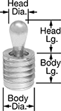 |
Threading makes these guide pins easier to remove and replace than press fit, so they're useful for high-wear applications. A sealed top prevents debris from getting inside and making them seize up. As the workpiece pushes against the pin head in one direction, the internal spring pushes back to hold it in place for clamping.
Pins | Installation Tools | ||||||||||||||
|---|---|---|---|---|---|---|---|---|---|---|---|---|---|---|---|
Body, mm | Head, mm | ||||||||||||||
Thread Size | Dia. | Lg. | Dia. | Lg. | Max. Head Movement, mm | Min. Spring Force | Max. Spring Force, lbf | Body Dia. Tolerance, mm | Body Material | Each | Each | ||||
Zinc-Plated Steel Head | |||||||||||||||
| M12 × 1.75 mm | 10 | 11.5 | 5 | 6 | 0.8 | Not Rated | 4.5 | -0.15 to 0.15 | Steel | 3077N11 | 00000 | 8485A93 | 000000 | ||
| M12 × 1.75 mm | 10 | 11.5 | 5 | 6 | 0.8 | Not Rated | 22 | -0.15 to 0.15 | Steel | 3077N14 | 0000 | 8485A93 | 00000 | ||
| M12 × 1.75 mm | 10 | 11.5 | 6 | 10 | 1 | Not Rated | 9 | -0.15 to 0.15 | Steel | 3077N12 | 0000 | 8485A93 | 00000 | ||
| M12 × 1.75 mm | 10 | 11.5 | 6 | 10 | 1 | Not Rated | 16 | -0.15 to 0.15 | Steel | 3077N13 | 0000 | 8485A93 | 00000 | ||
| M18 × 1.5 mm | 16 | 18 | 10 | 16 | 1.6 | Not Rated | 33 | -0.15 to 0.15 | Steel | 3077N15 | 0000 | 8485A94 | 00000 | ||
| M18 × 1.5 mm | 16 | 18 | 10 | 16 | 1.6 | Not Rated | 45 | -0.15 to 0.15 | Steel | 3077N16 | 0000 | 8485A94 | 00000 | ||
Create-Your-Own Spring Locating Pins
 |
Thread in a screw, handle, or other part to create the right size and shape guide pin for your application. As the workpiece pushes against the pin head in one direction, the internal spring pushes back to hold it in place for clamping. Press into a drilled hole using the installation tool (sold separately).
Sealed Spring Locating Pins
 |
Sealed at the top to prevent debris from getting inside and making them seize up, these guide pins are a good choice for machining fixtures. As the workpiece pushes against the pin head in one direction, the internal spring pushes back to hold it in place for clamping. Press into a drilled hole using the installation tool (sold separately).
Stainless Steel Head—Stainless steel pins are a good choice to avoid corrosion when working with stainless steel workpieces or fixtures.
Pins | Installation Tools | |||||||||||||
|---|---|---|---|---|---|---|---|---|---|---|---|---|---|---|
Body | Head | |||||||||||||
Dia. | Lg. | Dia. | Lg. | Max. Head Movement | Max. Spring Force, lbf | Body Dia. Min. Tolerance | Body Dia. Max. Tolerance | Body Material | Each | Each | ||||
Zinc-Plated Steel Head | ||||||||||||||
| 0.5" | 0.52" | 0.32" | 0.51" | 0.05" | 11 | 0.000" | 0.001" | Aluminum | 3074N21 | 000000 | 8485A83 | 000000 | ||
Stainless Steel Head | ||||||||||||||
| 0.25" | 0.28" | 0.12" | 0.16" | 0.02" | 4.5 | — | 0.004" | Aluminum | 3074N16 | 0000 | 8485A81 | 00000 | ||
| 0.44" | 0.37" | 0.24" | 0.41" | 0.04" | 6.7 | -0.0004" | 0.0004" | Aluminum | 3074N17 | 00000 | 8485A82 | 00000 | ||
| 0.63" | 0.68" | 0.39" | 0.68" | 0.06" | 18 | -0.0004" | 0.0004" | Aluminum | 3074N19 | 00000 | 8485A84 | 00000 | ||
Baseboard-Mount Door Stops
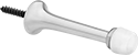 |
Style 2 |
Simply screw these bumpers into baseboards with the attached self-tapping wood screw to prevent doors from damaging walls. All of these stops have a nonmarking rubber pad, which is abrasion resistant.
Door Chains
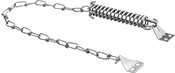 | 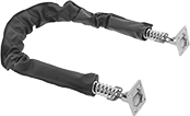 |
For Screen and Storm Doors | For Exterior Doors |
Mount one end to the frame and the other end to the door to prevent it from opening too far.
For Exterior Doors—Chains for exterior doors have a spring on each end for greater shock absorption than the stop for screen and storm doors. A vinyl cover protects the chain as well as surfaces from damage.
Finish | Material | For Door Wd. | Chain Lg. | No. of Springs | Mount Type | Mounting Fasteners Included | Features | Each | |||
|---|---|---|---|---|---|---|---|---|---|---|---|
For Screen and Storm Doors | |||||||||||
| Zinc Plated | Steel | 30", 32", 36" | 18" | 1 | Unthreaded Hole | Yes | — | 1472A12 | 00000 | ||
For Exterior Doors | |||||||||||
| Chrome Plated | Steel | 30" | 20 1/2" | 2 | Unthreaded Hole | Yes | Gray Vinyl Cover | 1472A33 | 00000 | ||
| Chrome Plated | Steel | 36" | 25 1/2" | 2 | Unthreaded Hole | Yes | Gray Vinyl Cover | 1472A35 | 00000 | ||
| Chrome Plated | Steel | 42" | 30 1/2" | 2 | Unthreaded Hole | Yes | Gray Vinyl Cover | 1472A37 | 00000 | ||
| Bronze Plated | Steel | 30" | 20 1/2" | 2 | Unthreaded Hole | Yes | Brown Vinyl Cover | 1472A38 | 00000 | ||
| Bronze Plated | Steel | 36" | 25 1/2" | 2 | Unthreaded Hole | Yes | Brown Vinyl Cover | 1472A39 | 00000 | ||
| Bronze Plated | Steel | 42" | 30 1/2" | 2 | Unthreaded Hole | Yes | Brown Vinyl Cover | 1472A41 | 00000 | ||
