


Filter by
Shaft Diameter
OD
Component


Hub Diameter


Shaft Mount Type

Shaft Type
Overall Width
Width


Export Control Classification Number (ECCN)
DFARS Specialty Metals
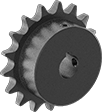
Sprockets
Metal Spur Gears
Gears
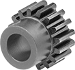 | 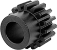 |  |
20° Pressure Angle Round Bore | Gear with Round or Round/Machinable Bore | Gear with Round Bore and Set Screw |
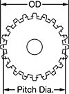
20° Pressure Angle—The current industry standard, these 20° pressure angle spur gears have thicker, stronger teeth than 14½° pressure angle gears.
14 1/2° Pressure Angle—A former industry standard, 14½° pressure angle gears are often found in older machinery.
Steel—Steel gears have hard, strong, and wear-resistant teeth, although they will rust when exposed to moisture and corrosive chemicals.
Brass—Brass gears are easy to machine, so you can add your own mounting holes and make other alterations. They won't rust when exposed to water.
Hub | |||||||||||||||||||||||||||||||||||||||||||||||||||||||||||||||||||||||||||||||||||||||||||||||||||
|---|---|---|---|---|---|---|---|---|---|---|---|---|---|---|---|---|---|---|---|---|---|---|---|---|---|---|---|---|---|---|---|---|---|---|---|---|---|---|---|---|---|---|---|---|---|---|---|---|---|---|---|---|---|---|---|---|---|---|---|---|---|---|---|---|---|---|---|---|---|---|---|---|---|---|---|---|---|---|---|---|---|---|---|---|---|---|---|---|---|---|---|---|---|---|---|---|---|---|---|
Gear Pitch | No. of Teeth | Gear Pitch Dia. | OD | Face Wd. | Dia. | Wd. | Bore Type | For Shaft Dia. | Tooth Heat Treatment | Material | Each | ||||||||||||||||||||||||||||||||||||||||||||||||||||||||||||||||||||||||||||||||||||||||
20° Pressure Angle | |||||||||||||||||||||||||||||||||||||||||||||||||||||||||||||||||||||||||||||||||||||||||||||||||||
Brass | |||||||||||||||||||||||||||||||||||||||||||||||||||||||||||||||||||||||||||||||||||||||||||||||||||
| 48 | 24 | 1/2" | 0.54" | 1/8" | 0.38" | 0.25" | Round Bore | 3/16" | — | Brass | 7880K21 | 000000 | |||||||||||||||||||||||||||||||||||||||||||||||||||||||||||||||||||||||||||||||||||||||
| 48 | 36 | 3/4" | 0.79" | 1/8" | 0.5" | 0.25" | Round Bore | 3/16" | — | Brass | 7880K23 | 00000 | |||||||||||||||||||||||||||||||||||||||||||||||||||||||||||||||||||||||||||||||||||||||
| 32 | 16 | 1/2" | 0.56" | 3/16" | 0.4" | 0.25" | Round Bore | 3/16" | — | Brass | 7880K27 | 00000 | |||||||||||||||||||||||||||||||||||||||||||||||||||||||||||||||||||||||||||||||||||||||
| 32 | 20 | 5/8" | 0.69" | 3/16" | 0.47" | 0.25" | Round Bore | 3/16" | — | Brass | 7880K29 | 00000 | |||||||||||||||||||||||||||||||||||||||||||||||||||||||||||||||||||||||||||||||||||||||
| 32 | 24 | 3/4" | 0.81" | 3/16" | 0.53" | 0.25" | Round Bore | 3/16" | — | Brass | 7880K31 | 00000 | |||||||||||||||||||||||||||||||||||||||||||||||||||||||||||||||||||||||||||||||||||||||
| 32 | 28 | 7/8" | 0.94" | 3/16" | 0.59" | 0.25" | Round Bore | 3/16" | — | Brass | 7880K32 | 00000 | |||||||||||||||||||||||||||||||||||||||||||||||||||||||||||||||||||||||||||||||||||||||
| 24 | 12 | 1/2" | 0.58" | 1/4" | 0.38" | 0.25" | Round Bore | 3/16" | — | Brass | 7880K37 | 00000 | |||||||||||||||||||||||||||||||||||||||||||||||||||||||||||||||||||||||||||||||||||||||
| 24 | 15 | 5/8" | 0.71" | 1/4" | 0.5" | 0.25" | Round Bore | 3/16" | — | Brass | 7880K38 | 00000 | |||||||||||||||||||||||||||||||||||||||||||||||||||||||||||||||||||||||||||||||||||||||
| 24 | 18 | 3/4" | 0.83" | 1/4" | 0.54" | 0.25" | Round Bore | 3/16" | — | Brass | 7880K39 | 00000 | |||||||||||||||||||||||||||||||||||||||||||||||||||||||||||||||||||||||||||||||||||||||
| 24 | 21 | 7/8" | 0.96" | 1/4" | 0.6" | 0.25" | Round Bore | 3/16" | — | Brass | 7880K41 | 00000 | |||||||||||||||||||||||||||||||||||||||||||||||||||||||||||||||||||||||||||||||||||||||
14 1/2° Pressure Angle | |||||||||||||||||||||||||||||||||||||||||||||||||||||||||||||||||||||||||||||||||||||||||||||||||||
Steel | |||||||||||||||||||||||||||||||||||||||||||||||||||||||||||||||||||||||||||||||||||||||||||||||||||
| 32 | 16 | 1/2" | 0.56" | 3/16" | 0.406" | 0.313" | Round Bore with Set Screw | 3/16" | Not Hardened | 1117 Carbon Steel | 6325K89 | 00000 | |||||||||||||||||||||||||||||||||||||||||||||||||||||||||||||||||||||||||||||||||||||||
| 32 | 18 | 0.563" | 0.63" | 3/16" | 0.406" | 0.313" | Round Bore | 3/16" | Not Hardened | 1117 Carbon Steel | 6325K94 | 00000 | |||||||||||||||||||||||||||||||||||||||||||||||||||||||||||||||||||||||||||||||||||||||
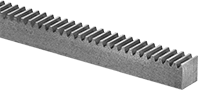
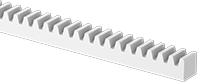
Gear Racks
 |
20° Pressure Angle—Rectangular |
 |
14 1/2° Pressure Angle—Rectangular |
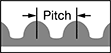
These racks match with spur gears to convert rotary motion to linear motion. For components to mesh correctly, they must have the same pressure angle and pitch/module.
Steel—Steel gear racks have strong and wear-resistant teeth, although they will rust when exposed to moisture and corrosive chemicals.
Brass—Brass gear racks are easy to machine, so you can add your own mounting holes and make other alterations. They won't rust when exposed to water.
Gear Pitch | Lg., ft. | Pitch Ht. | Ht. | Face Wd. | Tooth Heat Treatment | Material | Each | ||||||||||||||||||||||||||||||||||||||||||||||||||||||||||||||||||||||||||||||||||||||||||||
|---|---|---|---|---|---|---|---|---|---|---|---|---|---|---|---|---|---|---|---|---|---|---|---|---|---|---|---|---|---|---|---|---|---|---|---|---|---|---|---|---|---|---|---|---|---|---|---|---|---|---|---|---|---|---|---|---|---|---|---|---|---|---|---|---|---|---|---|---|---|---|---|---|---|---|---|---|---|---|---|---|---|---|---|---|---|---|---|---|---|---|---|---|---|---|---|---|---|---|---|
20° Pressure Angle—Rectangular | |||||||||||||||||||||||||||||||||||||||||||||||||||||||||||||||||||||||||||||||||||||||||||||||||||
Brass | |||||||||||||||||||||||||||||||||||||||||||||||||||||||||||||||||||||||||||||||||||||||||||||||||||
| 48 | 2 | 0.104" | 1/8" | 1/8" | — | Brass | 7854K12 | 0000000 | |||||||||||||||||||||||||||||||||||||||||||||||||||||||||||||||||||||||||||||||||||||||||||
| 32 | 2 | 0.156" | 3/16" | 3/16" | — | Brass | 7854K13 | 000000 | |||||||||||||||||||||||||||||||||||||||||||||||||||||||||||||||||||||||||||||||||||||||||||
| 24 | 2 | 0.208" | 1/4" | 1/4" | — | Brass | 7854K15 | 000000 | |||||||||||||||||||||||||||||||||||||||||||||||||||||||||||||||||||||||||||||||||||||||||||
14 1/2° Pressure Angle—Rectangular | |||||||||||||||||||||||||||||||||||||||||||||||||||||||||||||||||||||||||||||||||||||||||||||||||||
Steel | |||||||||||||||||||||||||||||||||||||||||||||||||||||||||||||||||||||||||||||||||||||||||||||||||||
| 32 | 2 | 0.156" | 3/16" | 3/16" | Not Hardened | 1018 Low-Carbon Steel | 6295K11 | 00000 | |||||||||||||||||||||||||||||||||||||||||||||||||||||||||||||||||||||||||||||||||||||||||||
| 32 | 4 | 0.156" | 3/16" | 3/16" | Not Hardened | 1215 Carbon Steel | 6295K242 | 00000 | |||||||||||||||||||||||||||||||||||||||||||||||||||||||||||||||||||||||||||||||||||||||||||
| 32 | 6 | 0.156" | 3/16" | 3/16" | Not Hardened | 1215 Carbon Steel | 6295K243 | 00000 | |||||||||||||||||||||||||||||||||||||||||||||||||||||||||||||||||||||||||||||||||||||||||||
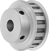
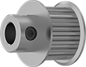
Timing Belt Pulleys
 |
Finished Bore |
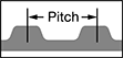 |
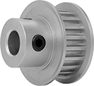
Keep your drive system in sync. Trapezoidal teeth mesh with matching belts to synchronize motion. With the original tooth profile, these pulleys handle enough torque for most applications. If you need high torque or precise starts and stops, consider curved tooth profiles, such as GT and HTD pulleys.
Steel—Strong but best for dry environments since moisture will cause them to rust.
Corrosion-Resistant Aluminum—Won't rust in wet environments and one-third the weight of steel and iron. However, aluminum pulleys are not as strong as iron and steel.
Finished Bore—Mount these pulleys onto the shaft and secure with a set screw—no machining required.
Flush Hub—Ideal in tight spots where a raised hub would get in the way.
For Max. Belt Wd. | Pitch | No. of Teeth | Bore Type | For Shaft Dia. | Pitch Dia. | No. of Flanges | Hub Type | Each | |||||||||||||||||||||||||||||||||||||||||||||||||||||||||||||||||||||||||||||||||||||||||||
|---|---|---|---|---|---|---|---|---|---|---|---|---|---|---|---|---|---|---|---|---|---|---|---|---|---|---|---|---|---|---|---|---|---|---|---|---|---|---|---|---|---|---|---|---|---|---|---|---|---|---|---|---|---|---|---|---|---|---|---|---|---|---|---|---|---|---|---|---|---|---|---|---|---|---|---|---|---|---|---|---|---|---|---|---|---|---|---|---|---|---|---|---|---|---|---|---|---|---|---|
For MXL Trade Size | |||||||||||||||||||||||||||||||||||||||||||||||||||||||||||||||||||||||||||||||||||||||||||||||||||
Corrosion-Resistant Aluminum | |||||||||||||||||||||||||||||||||||||||||||||||||||||||||||||||||||||||||||||||||||||||||||||||||||
| 1/8" | 0.080" | 15 | Finished | 3/16" | 0.382" | 1 | Standard | 1375K15 | 000000 | ||||||||||||||||||||||||||||||||||||||||||||||||||||||||||||||||||||||||||||||||||||||||||
| 1/8" | 0.080" | 16 | Finished | 3/16" | 0.407" | 1 | Standard | 1375K16 | 00000 | ||||||||||||||||||||||||||||||||||||||||||||||||||||||||||||||||||||||||||||||||||||||||||
| 1/8" | 0.080" | 18 | Finished | 3/16" | 0.458" | 2 | Standard | 1375K17 | 00000 | ||||||||||||||||||||||||||||||||||||||||||||||||||||||||||||||||||||||||||||||||||||||||||
| 1/4" | 0.080" | 15 | Finished | 3/16" | 0.382" | 1 | Standard | 1375K34 | 00000 | ||||||||||||||||||||||||||||||||||||||||||||||||||||||||||||||||||||||||||||||||||||||||||
| 1/4" | 0.080" | 16 | Finished | 3/16" | 0.407" | 1 | Standard | 1375K35 | 00000 | ||||||||||||||||||||||||||||||||||||||||||||||||||||||||||||||||||||||||||||||||||||||||||
| 1/4" | 0.080" | 18 | Finished | 3/16" | 0.458" | 2 | Standard | 1375K36 | 00000 | ||||||||||||||||||||||||||||||||||||||||||||||||||||||||||||||||||||||||||||||||||||||||||
For XL Trade Size | |||||||||||||||||||||||||||||||||||||||||||||||||||||||||||||||||||||||||||||||||||||||||||||||||||
Steel | |||||||||||||||||||||||||||||||||||||||||||||||||||||||||||||||||||||||||||||||||||||||||||||||||||
| 3/8" | 0.200" | 10 | Finished | 3/16" | 0.637" | 2 | Standard | 6495K711 | 00000 | ||||||||||||||||||||||||||||||||||||||||||||||||||||||||||||||||||||||||||||||||||||||||||
| 3/8" | 0.200" | 11 | Finished | 3/16" | 0.7" | 2 | Standard | 6495K712 | 00000 | ||||||||||||||||||||||||||||||||||||||||||||||||||||||||||||||||||||||||||||||||||||||||||
| 3/8" | 0.200" | 12 | Finished | 3/16" | 0.764" | 2 | Standard | 6495K713 | 00000 | ||||||||||||||||||||||||||||||||||||||||||||||||||||||||||||||||||||||||||||||||||||||||||
Corrosion-Resistant Aluminum | |||||||||||||||||||||||||||||||||||||||||||||||||||||||||||||||||||||||||||||||||||||||||||||||||||
| 1/4" | 0.200" | 10 | Finished | 3/16" | 0.637" | 2 | Standard | 1277N11 | 00000 | ||||||||||||||||||||||||||||||||||||||||||||||||||||||||||||||||||||||||||||||||||||||||||
| 1/4" | 0.200" | 12 | Finished | 3/16" | 0.764" | 2 | Standard | 1277N13 | 00000 | ||||||||||||||||||||||||||||||||||||||||||||||||||||||||||||||||||||||||||||||||||||||||||
| 3/8" | 0.200" | 10 | Finished | 3/16" | 0.637" | 2 | Flush | 1277N735 | 00000 | ||||||||||||||||||||||||||||||||||||||||||||||||||||||||||||||||||||||||||||||||||||||||||
| 3/8" | 0.200" | 10 | Finished | 3/16" | 0.637" | 2 | Standard | 1277N41 | 00000 | ||||||||||||||||||||||||||||||||||||||||||||||||||||||||||||||||||||||||||||||||||||||||||
| 3/8" | 0.200" | 11 | Finished | 3/16" | 0.7" | 2 | Standard | 1277N42 | 00000 | ||||||||||||||||||||||||||||||||||||||||||||||||||||||||||||||||||||||||||||||||||||||||||
| 3/8" | 0.200" | 12 | Finished | 3/16" | 0.764" | 2 | Flush | 1277N738 | 00000 | ||||||||||||||||||||||||||||||||||||||||||||||||||||||||||||||||||||||||||||||||||||||||||
| 3/8" | 0.200" | 12 | Finished | 3/16" | 0.764" | 2 | Standard | 1277N43 | 00000 | ||||||||||||||||||||||||||||||||||||||||||||||||||||||||||||||||||||||||||||||||||||||||||
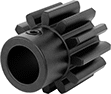
Plastic Spur Gears
Gears
 | |
20° Pressure Angle | 14 1/2° Pressure Angle, Round Bore |
20° Pressure Angle—The current industry standard, these 20° pressure angle spur gears have thicker, stronger teeth than 14½° pressure angle gears.
14 1/2° Pressure Angle—A former industry standard, 14½° pressure angle gears are often found in older machinery.
Acetal—Acetal gears absorb less water than nylon gears, so they’re less likely to swell.
Nylon—Nylon gears are wear resistant, but will swell and weaken over time when wet.
Hub | |||||||||||||||||||||||||||||||||||||||||||||||||||||||||||||||||||||||||||||||||||||||||||||||||||
|---|---|---|---|---|---|---|---|---|---|---|---|---|---|---|---|---|---|---|---|---|---|---|---|---|---|---|---|---|---|---|---|---|---|---|---|---|---|---|---|---|---|---|---|---|---|---|---|---|---|---|---|---|---|---|---|---|---|---|---|---|---|---|---|---|---|---|---|---|---|---|---|---|---|---|---|---|---|---|---|---|---|---|---|---|---|---|---|---|---|---|---|---|---|---|---|---|---|---|---|
Gear Pitch | No. of Teeth | Gear Pitch Dia. | OD | Face Wd. | Dia. | Wd. | Bore Type | For Shaft Dia. | Color | Each | |||||||||||||||||||||||||||||||||||||||||||||||||||||||||||||||||||||||||||||||||||||||||
20° Pressure Angle | |||||||||||||||||||||||||||||||||||||||||||||||||||||||||||||||||||||||||||||||||||||||||||||||||||
Acetal | |||||||||||||||||||||||||||||||||||||||||||||||||||||||||||||||||||||||||||||||||||||||||||||||||||
| 48 | 36 | 3/4" | 0.79" | 1/8" | 0.547" | 0.25" | Round Bore | 3/16" | White | 2662N24 | 00000 | ||||||||||||||||||||||||||||||||||||||||||||||||||||||||||||||||||||||||||||||||||||||||
| 32 | 24 | 3/4" | 0.81" | 3/16" | 0.5" | 0.313" | Round Bore | 3/16" | White | 2662N15 | 0000 | ||||||||||||||||||||||||||||||||||||||||||||||||||||||||||||||||||||||||||||||||||||||||
| 24 | 12 | 1/2" | 0.54" | 1/4" | 0.375" | 0.313" | Round Bore | 3/16" | White | 2662N7 | 0000 | ||||||||||||||||||||||||||||||||||||||||||||||||||||||||||||||||||||||||||||||||||||||||
| 24 | 18 | 3/4" | 0.83" | 1/4" | 0.547" | 0.313" | Round Bore | 3/16" | White | 2662N8 | 0000 | ||||||||||||||||||||||||||||||||||||||||||||||||||||||||||||||||||||||||||||||||||||||||
14 1/2° Pressure Angle | |||||||||||||||||||||||||||||||||||||||||||||||||||||||||||||||||||||||||||||||||||||||||||||||||||
Nylon | |||||||||||||||||||||||||||||||||||||||||||||||||||||||||||||||||||||||||||||||||||||||||||||||||||
| 48 | 36 | 3/4" | 0.79" | 1/8" | 0.625" | 0.25" | Round Bore | 3/16" | White | 57655K19 | 00000 | ||||||||||||||||||||||||||||||||||||||||||||||||||||||||||||||||||||||||||||||||||||||||
| 48 | 40 | 0.833" | 0.87" | 1/8" | 0.625" | 0.25" | Round Bore | 3/16" | White | 57655K21 | 00000 | ||||||||||||||||||||||||||||||||||||||||||||||||||||||||||||||||||||||||||||||||||||||||
| 48 | 48 | 1" | 1.04" | 1/8" | 0.625" | 0.25" | Round Bore | 3/16" | White | 57655K24 | 00000 | ||||||||||||||||||||||||||||||||||||||||||||||||||||||||||||||||||||||||||||||||||||||||
| 48 | 56 | 1.167" | 1.2" | 1/8" | 0.625" | 0.25" | Round Bore | 3/16" | White | 57655K25 | 00000 | ||||||||||||||||||||||||||||||||||||||||||||||||||||||||||||||||||||||||||||||||||||||||
| 32 | 16 | 1/2" | 0.56" | 3/16" | 0.375" | 0.25" | Round Bore | 3/16" | White | 57655K34 | 00000 | ||||||||||||||||||||||||||||||||||||||||||||||||||||||||||||||||||||||||||||||||||||||||
| 32 | 18 | 0.563" | 0.63" | 3/16" | 0.375" | 0.25" | Round Bore | 3/16" | White | 57655K35 | 00000 | ||||||||||||||||||||||||||||||||||||||||||||||||||||||||||||||||||||||||||||||||||||||||
| 32 | 20 | 5/8" | 0.69" | 3/16" | 0.5" | 0.25" | Round Bore | 3/16" | White | 57655K36 | 00000 | ||||||||||||||||||||||||||||||||||||||||||||||||||||||||||||||||||||||||||||||||||||||||
| 32 | 24 | 3/4" | 0.81" | 3/16" | 0.625" | 0.25" | Round Bore | 3/16" | White | 57655K38 | 00000 | ||||||||||||||||||||||||||||||||||||||||||||||||||||||||||||||||||||||||||||||||||||||||
| 32 | 28 | 7/8" | 0.94" | 3/16" | 0.625" | 0.25" | Round Bore | 3/16" | White | 57655K41 | 00000 | ||||||||||||||||||||||||||||||||||||||||||||||||||||||||||||||||||||||||||||||||||||||||
Gear Racks
 |
20° Pressure Angle—Rectangular |
|
14 1/2° Pressure Angle—Rectangular |
Gear Pitch | Lg., ft. | Pitch Ht. | Ht. | Face Wd. | Fabrication | Color | Each | ||||||||||||||||||||||||||||||||||||||||||||||||||||||||||||||||||||||||||||||||||||||||||||
|---|---|---|---|---|---|---|---|---|---|---|---|---|---|---|---|---|---|---|---|---|---|---|---|---|---|---|---|---|---|---|---|---|---|---|---|---|---|---|---|---|---|---|---|---|---|---|---|---|---|---|---|---|---|---|---|---|---|---|---|---|---|---|---|---|---|---|---|---|---|---|---|---|---|---|---|---|---|---|---|---|---|---|---|---|---|---|---|---|---|---|---|---|---|---|---|---|---|---|---|
20° Pressure Angle—Rectangular | |||||||||||||||||||||||||||||||||||||||||||||||||||||||||||||||||||||||||||||||||||||||||||||||||||
Acetal | |||||||||||||||||||||||||||||||||||||||||||||||||||||||||||||||||||||||||||||||||||||||||||||||||||
| 48 | 1 | 0.109" | 1/8" | 1/8" | Molded | Gray | 2662N54 | 00000 | |||||||||||||||||||||||||||||||||||||||||||||||||||||||||||||||||||||||||||||||||||||||||||
| 32 | 1 | 0.156" | 3/16" | 3/16" | Molded | Gray | 2662N53 | 0000 | |||||||||||||||||||||||||||||||||||||||||||||||||||||||||||||||||||||||||||||||||||||||||||
| 24 | 1 | 0.203" | 1/4" | 1/4" | Molded | Gray | 2662N52 | 0000 | |||||||||||||||||||||||||||||||||||||||||||||||||||||||||||||||||||||||||||||||||||||||||||
14 1/2° Pressure Angle—Rectangular | |||||||||||||||||||||||||||||||||||||||||||||||||||||||||||||||||||||||||||||||||||||||||||||||||||
Nylon | |||||||||||||||||||||||||||||||||||||||||||||||||||||||||||||||||||||||||||||||||||||||||||||||||||
| 48 | 1 | 0.109" | 1/8" | 1/8" | Molded | White | 57655K61 | 0000 | |||||||||||||||||||||||||||||||||||||||||||||||||||||||||||||||||||||||||||||||||||||||||||
| 32 | 1 | 0.156" | 3/16" | 3/16" | Molded | White | 57655K62 | 0000 | |||||||||||||||||||||||||||||||||||||||||||||||||||||||||||||||||||||||||||||||||||||||||||
Plastic Timing Belt Pulleys
 | |
Naturally rust resistant and lightweight, these plastic pulleys are ideal for machines that require frequent washdowns. Trapezoidal teeth, the original tooth profile, mesh with matching belts to transmit power without slipping.
Finished Bore—Mount these pulleys onto the shaft and secure with a set screw—no machining required.
Plain Bore—Do it your way—machine the bore to your exact shaft size or add a set screw or keyway.
For Max. Belt Wd. | Pitch | No. of Teeth | Bore Type | For Shaft Dia. | Pitch Dia. | No. of Flanges | Hub Type | Each | |||||||||||||||||||||||||||||||||||||||||||||||||||||||||||||||||||||||||||||||||||||||||||
|---|---|---|---|---|---|---|---|---|---|---|---|---|---|---|---|---|---|---|---|---|---|---|---|---|---|---|---|---|---|---|---|---|---|---|---|---|---|---|---|---|---|---|---|---|---|---|---|---|---|---|---|---|---|---|---|---|---|---|---|---|---|---|---|---|---|---|---|---|---|---|---|---|---|---|---|---|---|---|---|---|---|---|---|---|---|---|---|---|---|---|---|---|---|---|---|---|---|---|---|
For MXL Trade Size | |||||||||||||||||||||||||||||||||||||||||||||||||||||||||||||||||||||||||||||||||||||||||||||||||||
Polycarbonate | |||||||||||||||||||||||||||||||||||||||||||||||||||||||||||||||||||||||||||||||||||||||||||||||||||
| 1/4" | 0.080" | 18 | Plain | 3/16" | 0.458" | 2 | Standard | 1254N17 | 00000 | ||||||||||||||||||||||||||||||||||||||||||||||||||||||||||||||||||||||||||||||||||||||||||
| 1/4" | 0.080" | 20 | Plain | 3/16" | 0.509" | 2 | Standard | 1254N18 | 0000 | ||||||||||||||||||||||||||||||||||||||||||||||||||||||||||||||||||||||||||||||||||||||||||
| 1/4" | 0.080" | 21 | Plain | 3/16" | 0.535" | 2 | Standard | 1254N19 | 0000 | ||||||||||||||||||||||||||||||||||||||||||||||||||||||||||||||||||||||||||||||||||||||||||
| 1/4" | 0.080" | 22 | Plain | 3/16" | 0.56" | 2 | Standard | 1254N2 | 0000 | ||||||||||||||||||||||||||||||||||||||||||||||||||||||||||||||||||||||||||||||||||||||||||
| 1/4" | 0.080" | 24 | Plain | 3/16" | 0.611" | 2 | Standard | 1254N21 | 0000 | ||||||||||||||||||||||||||||||||||||||||||||||||||||||||||||||||||||||||||||||||||||||||||
For XL Trade Size | |||||||||||||||||||||||||||||||||||||||||||||||||||||||||||||||||||||||||||||||||||||||||||||||||||
Acetal | |||||||||||||||||||||||||||||||||||||||||||||||||||||||||||||||||||||||||||||||||||||||||||||||||||
| 3/8" | 0.200" | 10 | Finished | 3/16" | 0.637" | 2 | Standard | 57105K11 | 00000 | ||||||||||||||||||||||||||||||||||||||||||||||||||||||||||||||||||||||||||||||||||||||||||
| 3/8" | 0.200" | 11 | Finished | 3/16" | 0.7" | 2 | Standard | 57105K12 | 00000 | ||||||||||||||||||||||||||||||||||||||||||||||||||||||||||||||||||||||||||||||||||||||||||
| 3/8" | 0.200" | 12 | Finished | 3/16" | 0.764" | 2 | Standard | 57105K13 | 00000 | ||||||||||||||||||||||||||||||||||||||||||||||||||||||||||||||||||||||||||||||||||||||||||
Precision High-Torque GT Timing Belt Pulleys
 |
Finished Bore |
 |
When precise synchronization is crucial, these pulleys minimize play (backlash). They’re often found in 3D printers, where accurate positioning is essential. Their curved teeth fit snugly with matching belts. Compared to pulleys with standard trapezoidal teeth, these pulleys transmit about three times more torque and run at higher speeds. All are compatible with Gates PowerGrip GT, 2GT, GT2, GT3, and GT4 series.
Corrosion-Resistant Aluminum—Won't rust in wet environments and one-third the weight of steel and iron. However, aluminum pulleys are not as strong as iron and steel.
Finished Bore—Mount these pulleys onto the shaft and secure with a set screw—no machining required.
For Max. Belt Wd., mm | Pitch, mm | No. of Teeth | Bore Type | For Shaft Dia. | Pitch Dia., mm | No. of Flanges | Hub Type | Each | |||||||||||||||||||||||||||||||||||||||||||||||||||||||||||||||||||||||||||||||||||||||||||
|---|---|---|---|---|---|---|---|---|---|---|---|---|---|---|---|---|---|---|---|---|---|---|---|---|---|---|---|---|---|---|---|---|---|---|---|---|---|---|---|---|---|---|---|---|---|---|---|---|---|---|---|---|---|---|---|---|---|---|---|---|---|---|---|---|---|---|---|---|---|---|---|---|---|---|---|---|---|---|---|---|---|---|---|---|---|---|---|---|---|---|---|---|---|---|---|---|---|---|---|
For 2MGT Trade Size | |||||||||||||||||||||||||||||||||||||||||||||||||||||||||||||||||||||||||||||||||||||||||||||||||||
Corrosion-Resistant Aluminum | |||||||||||||||||||||||||||||||||||||||||||||||||||||||||||||||||||||||||||||||||||||||||||||||||||
| 6 | 2 | 15 | Finished | 3/16" | 9.6 | 1 | Standard | 3764N103 | 000000 | ||||||||||||||||||||||||||||||||||||||||||||||||||||||||||||||||||||||||||||||||||||||||||
| 6 | 2 | 16 | Finished | 3/16" | 10.2 | 1 | Standard | 3764N104 | 00000 | ||||||||||||||||||||||||||||||||||||||||||||||||||||||||||||||||||||||||||||||||||||||||||
For 3MGT Trade Size | |||||||||||||||||||||||||||||||||||||||||||||||||||||||||||||||||||||||||||||||||||||||||||||||||||
Corrosion-Resistant Aluminum | |||||||||||||||||||||||||||||||||||||||||||||||||||||||||||||||||||||||||||||||||||||||||||||||||||
| 9 | 3 | 16 | Finished | 3/16" | 15.3 | 1 | Standard | 3764N124 | 00000 | ||||||||||||||||||||||||||||||||||||||||||||||||||||||||||||||||||||||||||||||||||||||||||
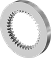
Plastic Miter Gears
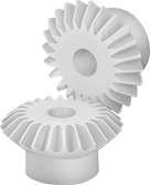 |  |  |
Gears Sold Separately |
Connect two shafts at a right angle without changing shaft speed or torque. Made of plastic, these gears run quieter than metal gears and have good corrosion and chemical resistance.
For two gears to mesh correctly, they must have the same pressure angle, pitch/module, and number of teeth.
Nylon—Nylon gears are self-lubricating, so they’re often used in food machinery. However, they’re not approved for direct contact with food or chemicals that will come into contact with food.
Hub | |||||||||||||||||||||||||||||||||||||||||||||||||||||||||||||||||||||||||||||||||||||||||||||||||||
|---|---|---|---|---|---|---|---|---|---|---|---|---|---|---|---|---|---|---|---|---|---|---|---|---|---|---|---|---|---|---|---|---|---|---|---|---|---|---|---|---|---|---|---|---|---|---|---|---|---|---|---|---|---|---|---|---|---|---|---|---|---|---|---|---|---|---|---|---|---|---|---|---|---|---|---|---|---|---|---|---|---|---|---|---|---|---|---|---|---|---|---|---|---|---|---|---|---|---|---|
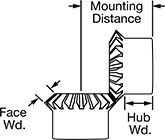
Gear Pitch | No. of Teeth | Pressure Angle | Gear Pitch Dia. | OD | Face Wd. | Overall Wd. | For Shaft Dia. | Mounting Distance | Material | Fabrication | Color | Dia. | Wd. | Each | |||||||||||||||||||||||||||||||||||||||||||||||||||||||||||||||||||||||||||||||||||||
Round Bore | |||||||||||||||||||||||||||||||||||||||||||||||||||||||||||||||||||||||||||||||||||||||||||||||||||
| 48 | 24 | 20° | 1/2" | 0.53" | 0.09" | 0.375" | 3/16" | 0.531" | Nylon | Molded | White | 0.375" | 0.25" | 7297K12 | 000000 | ||||||||||||||||||||||||||||||||||||||||||||||||||||||||||||||||||||||||||||||||||||
| 32 | 16 | 20° | 1/2" | 0.55" | 0.11" | 0.344" | 3/16" | 0.5" | Nylon | Molded | White | 0.406" | 0.188" | 7297K13 | 00000 | ||||||||||||||||||||||||||||||||||||||||||||||||||||||||||||||||||||||||||||||||||||
| 32 | 24 | 20° | 3/4" | 0.8" | 0.16" | 0.406" | 3/16" | 0.688" | Nylon | Molded | White | 0.5" | 0.188" | 7297K14 | 00000 | ||||||||||||||||||||||||||||||||||||||||||||||||||||||||||||||||||||||||||||||||||||
High-Torque HTD Timing Belt Pulleys
 |  |
Finished Bore |
Curved teeth engage with the matching belt better than standard trapezoidal teeth, so these pulleys transmit about twice the torque. All are compatible with Gates PowerGrip HTD, Omega HP, and Carlisle RPP series.
Corrosion-Resistant Aluminum—Won't rust in wet environments and one-third the weight of steel and iron. However, aluminum pulleys are not as strong as iron and steel.
Finished Bore—Mount these pulleys onto the shaft and secure with a set screw—no machining required.
