About Roller Chain and Sprockets
More
About Gears
More
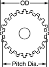
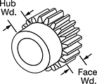
Sprockets for ANSI Roller Chain
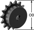
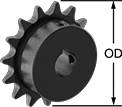
Mount these sprockets onto your shaft and secure with a set screw—no machining necessary.
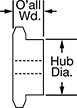
Keyway | ||||||||||
|---|---|---|---|---|---|---|---|---|---|---|
| Number of Teeth | For Shaft Dia. | OD | Overall Wd. | Hub Dia. | Wd. | Dp. | Material | Includes | Each | |
| 70 | 1/2" | 5.72" | 3/4" | 2" | __ | __ | Steel | Two Set Screws | 00000000 | 000000 |
| 70 | 5/8" | 5.72" | 3/4" | 2" | 3/16" | 3/32" | Steel | Two Set Screws | 00000000 | 00000 |
| 70 | 3/4" | 5.72" | 3/4" | 2" | 3/16" | 3/32" | Steel | Two Set Screws | 00000000 | 00000 |
| 70 | 7/8" | 5.72" | 3/4" | 2" | 3/16" | 3/32" | Steel | Two Set Screws | 00000000 | 00000 |
| 70 | 1" | 5.72" | 3/4" | 2" | 1/4" | 1/8" | Steel | Two Set Screws | 00000000 | 00000 |
| 70 | 1 1/4" | 5.72" | 3/4" | 2" | 1/4" | 1/8" | Steel | Two Set Screws | 00000000 | 00000 |
| 70 | 1 3/8" | 5.72" | 3/4" | 2" | 5/16" | 5/32" | Steel | Two Set Screws | 00000000 | 00000 |
Keyway | ||||||||||
|---|---|---|---|---|---|---|---|---|---|---|
| Number of Teeth | For Shaft Dia. | OD | Overall Wd. | Hub Dia. | Wd. | Dp. | Material | Includes | Each | |
| 70 | 3/4" | 11.43" | 1 1/4" | 4" | 3/16" | 3/32" | Steel | Two Set Screws | 00000000 | 0000000 |
| 70 | 7/8" | 11.43" | 1 1/4" | 4" | 3/16" | 3/32" | Steel | Two Set Screws | 00000000 | 000000 |
| 70 | 1" | 11.43" | 1 1/4" | 4" | 1/4" | 1/8" | Steel | Two Set Screws | 00000000 | 000000 |
| 70 | 1 1/4" | 11.43" | 1 1/4" | 4" | 1/4" | 1/8" | Steel | Two Set Screws | 00000000 | 000000 |
| 70 | 1 3/8" | 11.43" | 1 1/4" | 4" | 5/16" | 5/32" | Steel | Two Set Screws | 00000000 | 000000 |
| 70 | 1 1/2" | 11.43" | 1 1/4" | 4" | 3/8" | 3/16" | Steel | Two Set Screws | 00000000 | 000000 |
Keyway | ||||||||||
|---|---|---|---|---|---|---|---|---|---|---|
| Number of Teeth | For Shaft Dia. | OD | Overall Wd. | Hub Dia. | Wd. | Dp. | Material | Includes | Each | |
| 70 | 3/4" | 11.43" | 1 3/16" | 4" | 3/16" | 3/32" | Steel | Two Set Screws | 00000000 | 0000000 |
| 70 | 1" | 11.43" | 1 3/16" | 4" | 1/4" | 1/8" | Steel | Two Set Screws | 00000000 | 000000 |
| 70 | 1 1/4" | 11.43" | 1 3/16" | 4" | 1/4" | 1/8" | Steel | Two Set Screws | 00000000 | 000000 |
| 70 | 1 1/2" | 11.43" | 1 3/16" | 4" | 3/8" | 3/16" | Steel | Two Set Screws | 00000000 | 000000 |
Keyway | ||||||||||
|---|---|---|---|---|---|---|---|---|---|---|
| Number of Teeth | For Shaft Dia. | OD | Overall Wd. | Hub Dia. | Wd. | Dp. | Material | Includes | Each | |
| 70 | 1" | 14.29" | 1 3/4" | 3 3/4" | 1/4" | 1/8" | Steel | Two Set Screws | 00000000 | 0000000 |
| 70 | 1 1/8" | 14.29" | 1 3/4" | 3 3/4" | 1/4" | 1/8" | Steel | Two Set Screws | 00000000 | 000000 |
| 70 | 1 3/16" | 14.29" | 1 3/4" | 3 3/4" | 1/4" | 1/8" | Steel | Two Set Screws | 00000000 | 000000 |
| 70 | 1 1/4" | 14.29" | 1 3/4" | 3 3/4" | 1/4" | 1/8" | Steel | Two Set Screws | 00000000 | 000000 |
| 70 | 1 3/8" | 14.29" | 1 3/4" | 3 3/4" | 5/16" | 5/32" | Steel | Two Set Screws | 00000000 | 000000 |
| 70 | 1 7/16" | 14.29" | 1 3/4" | 3 3/4" | 3/8" | 3/16" | Steel | Two Set Screws | 00000000 | 000000 |
| 70 | 1 1/2" | 14.29" | 1 3/4" | 3 3/4" | 3/8" | 3/16" | Steel | Two Set Screws | 00000000 | 000000 |
| 70 | 1 5/8" | 14.29" | 1 3/4" | 3 3/4" | 3/8" | 3/16" | Steel | Two Set Screws | 00000000 | 000000 |
| 70 | 1 3/4" | 14.29" | 1 3/4" | 3 3/4" | 3/8" | 3/16" | Steel | Two Set Screws | 00000000 | 000000 |
| 70 | 1 15/16" | 14.29" | 1 3/4" | 3 3/4" | 1/2" | 1/4" | Steel | Two Set Screws | 00000000 | 000000 |
Keyway | ||||||||||
|---|---|---|---|---|---|---|---|---|---|---|
| Number of Teeth | For Shaft Dia. | OD | Overall Wd. | Hub Dia. | Wd. | Dp. | Material | Includes | Each | |
| 70 | 1 3/8" | 17.15" | 1 3/4" | 4 1/4" | 5/16" | 5/32" | Steel | Two Set Screws | 00000000 | 0000000 |
| 70 | 1 7/16" | 17.15" | 1 3/4" | 4 1/4" | 3/8" | 3/16" | Steel | Two Set Screws | 00000000 | 000000 |
| 70 | 1 1/2" | 17.15" | 1 3/4" | 4 1/4" | 3/8" | 3/16" | Steel | Two Set Screws | 00000000 | 000000 |
| 70 | 1 5/8" | 17.15" | 1 3/4" | 4 1/4" | 3/8" | 3/16" | Steel | Two Set Screws | 00000000 | 000000 |
| 70 | 1 3/4" | 17.15" | 1 3/4" | 4 1/4" | 3/8" | 3/16" | Steel | Two Set Screws | 00000000 | 000000 |
| 70 | 1 15/16" | 17.15" | 1 3/4" | 4 1/4" | 1/2" | 1/4" | Steel | Two Set Screws | 00000000 | 000000 |
| 70 | 2" | 17.15" | 1 3/4" | 4 1/4" | 1/2" | 1/4" | Steel | Two Set Screws | 00000000 | 000000 |
| 70 | 2 3/16" | 17.15" | 1 3/4" | 4 1/4" | 1/2" | 1/4" | Steel | Two Set Screws | 00000000 | 000000 |
| 70 | 2 7/16" | 17.15" | 1 3/4" | 4 1/4" | 5/8" | 5/16" | Steel | Two Set Screws | 00000000 | 000000 |
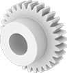
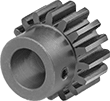
Metal Gears and Gear Racks—20° Pressure Angle
The current industry standard, these 20° pressure angle gears have thicker, stronger teeth than 14½° pressure angle gears. Compared to plastic gears and racks, they’re better for high-load, high-speed, and heavy duty applications. Also known as spur gears.
Combine gears with different numbers of teeth to change speed and torque in your assembly. Combine a gear and rack to convert rotary motion into linear motion. To minimize your footprint, mount one or more standard gears inside of an internal gear.
For components to mesh correctly, they must have the same pressure angle and pitch/module.
Brass gears and racks are easy to machine, so you can add your own mounting holes and make other alterations. They won't rust when exposed to water.
Carbon steel components have hard, strong, and wear-resistant teeth, although they will rust when exposed to moisture and corrosive chemicals. They're best for high-torque machines, like lifting equipment, and heavy duty applications, such as rock crushing. Gears with teeth that are not hardened can be hardened to fit your application.
Plastic Gears and Gear Racks—20° Pressure Angle
The current industry standard, these 20° pressure angle gears have thicker, stronger teeth than 14½° pressure angle gears. Made of plastic, they run quieter than metal gears and have good corrosion and chemical resistance. They’re also known as spur gears.
Combine gears with different numbers of teeth to change speed and torque in your assembly. Combine a gear and rack to convert rotary motion into linear motion.
For components to mesh correctly, they must have the same pressure angle and pitch/module.
Acetal gears are best suited for use in light duty machines or for prototyping.