Certificate Certificate |
---|
![]() | |
RoHS (Restriction of Hazardous Substances) RoHS (Restriction ofHazardous Substances) |
---|
|
REACH (Registration, Evaluation, Authorization and Restriction of Chemicals) REACH (Registration,Evaluation, Authorization and Restriction of Chemicals) |
---|
|
DFARS (Defense Acquisition Regulations Supplement) DFARS (Defense AcquisitionRegulations Supplement) |
---|
Capacity @ Hanger Spacing Capacity @ Hanger Spacing |
---|
|
Capacity Capacity |
---|
|
|
About Carbon Steel, Alloy Steel, Spring Steel, and Cast Iron
More
Low-Carbon Steel I-Beams

- Yield Strength: 50,000 psi
- Hardness: Not Rated
- Heat Treatable: Yes
- Specifications Met: ASTM A992
Made of rigid low-carbon steel, these I-beams are often used in construction, framing, lifting, and hoisting applications. Also known as mild steel, low-carbon steel is the most commonly used material for I-beams. It deflects less under load than medium- or high-carbon steel and is less likely to crack from welding. These I-beams have rounded corners, and are also known as American Standard I-beams. They weigh less than low-carbon steel H-bars, but are not as strong.
For technical drawings and 3-D models, click on a part number.
Certificates with a traceable lot number are available for these products. Download certificates from ORDER HISTORY after your order ships.
Outside | ||||||||
---|---|---|---|---|---|---|---|---|
Wall Thickness | Height | Height Tolerance | Width | Width Tolerance | Straightness Tolerance | 3 ft. Lg. | 6 ft. Lg. | |
0.26" | 3" | -0.063" to 0.094" | 2.33" | -0.125" to 0.125" | 0.025" per ft. | 0000000 | ||
0.293" | 4" | -0.063" to 0.094" | 2.663" | -0.125" to 0.125" | 0.025" per ft. | 0000000 | ||
0.359" | 6" | -0.063" to 0.094" | 3.332" | -0.125" to 0.125" | 0.0125" per ft. | 0000000 | ||
0.425" | 8" | -0.094" to 0.125" | 4.001" | -0.156" to 0.156" | 0.0125" per ft. | 0000000 |
Low-Carbon Steel H-Bars

- Yield Strength: 50,000 psi
- Hardness: Not Rated
- Heat Treatable: Yes
- Maximum Hardness After Heat Treatment: Not Rated
- Specifications Met: ASTM A992
Made of stiff low-carbon steel to deflect less under load, these H-bars are commonly used in machine bases, construction, platforms, and frames. Because of its rigidity, low-carbon steel is the most commonly used material for H-bars. These H-bars are less likely to crack from welding than those made of higher-carbon steels, and easier to weld than I-beams because they have a straight flange instead of a radius flange. H-bars are stronger than I-beams, but also heavier.
For technical drawings and 3-D models, click on a part number.
Certificates with a traceable lot number are available for these products. Download certificates from ORDER HISTORY after your order ships.
Outside | |||||||||||
---|---|---|---|---|---|---|---|---|---|---|---|
Wall Thickness | Wall Thickness Tolerance | Height | Height Tolerance | Width | Width Tolerance | Inside Width | Minimum Temperature, °F | Straightness Tolerance | 3 ft., Lg. | 6 ft., Lg. | |
0.215" | Not Rated | 3.94" | -0.188" to 0.250" | 5.9" | -0.125" to 0.125" | 5.47" | Not Rated | 0.025" per ft. | 0000000 | ||
0.26" | Not Rated | 5.99" | -0.188" to 0.250" | 5.99" | -0.125" to 0.125" | 5.47" | Not Rated | 0.025" per ft. | 0000000 | ||
0.28" | Not Rated | 4" | -0.188" to 0.250" | 6.03" | -0.125" to 0.125" | 5.47" | Not Rated | 0.025" per ft. | 0000000 | ||
0.345" | Not Rated | 4.06" | -0.188" to 0.250" | 4.16" | -0.125" to 0.125" | 3.47" | Not Rated | 0.025" per ft. | 0000000 | ||
0.365" | Not Rated | 6.02" | -0.188" to 0.250" | 6.2" | -0.125" to 0.125" | 5.47" | Not Rated | 0.025" per ft. | 0000000 | ||
0.4" | Not Rated | 5.27" | -0.188" to 0.250" | 8.28" | -0.125" to 0.125" | 7.48" | Not Rated | 0.025" per ft. | 0000000 | ||
0.435" | Not Rated | 7.995" | -0.188" to 0.250" | 8" | -0.125" to 0.125" | 7.13" | Not Rated | 0.025" per ft. | 0000000 | ||
0.455" | Not Rated | 6.08" | -0.188" to 0.250" | 6.38" | -0.125" to 0.125" | 5.47" | Not Rated | 0.025" per ft. | 0000000 | ||
0.56" | Not Rated | 8.07" | -0.188" to 0.250" | 8.25" | -0.125" to 0.125" | 7.13" | Not Rated | 0.025" per ft. | 0000000 |
Track for Overhead Beam Conveyors

Track provides the runway for trolleys in manual and powered systems.
Note: Not designed for building structural support.
For technical drawings and 3-D models, click on a part number.
Hooks for Powered Overhead Beam Conveyors

Hooks allow items to rotate 90° degrees while suspended. They attach to trolleys with a bolt and nut.
For technical drawings and 3-D models, click on a part number.
Hook | ||||||||
---|---|---|---|---|---|---|---|---|
Opening Wd. | Usable Lg. | Movement | Material | Mounting Fasteners Included | Mounting Hole Dia. | Max. Temp., °F | Each | |
1 1/4" | 4 1/8" | 90° Rotation | Iron | No | 1/2" | 450° | 0000000 | 000000 |
Trolleys for Manual Overhead Beam Conveyors

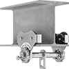
Prevent excess wear on the track and trolley—only the wheels of these push trolleys come in contact with the beam. Trolleys can be installed anywhere along the beam.
For technical drawings and 3-D models, click on a part number.
Trolleys for Powered Overhead Beam Conveyors

Use with conveying chain to automatically move these trolleys along the beam. The two-bolt bottom connection keeps the trolleys from loosening during use.
For technical drawings and 3-D models, click on a part number.
Chain for Powered Overhead Beam Conveyors


Chain connects trolleys and guides movement along the track. It can be assembled and disassembled without tools, yet its design makes it difficult to disconnect while in use.
For technical drawings and 3-D models, click on a part number.
Fork-Mount Lifting Adapters
Use these adapters to convert a forklift for vertical lifting. They have latch hooks to connect to the load.
Style C have L-shaped fork brackets that accommodate a pair of forks of any width.
Warning: Never use to lift people or items over people.

For Max. Fork | Overall | ||||||||||||
---|---|---|---|---|---|---|---|---|---|---|---|---|---|
Style | Hook Cap., lbs. | Hook Movement | No. of Fork Pockets | Ht. | Wd. | Ht. | Forklift Attachment Type | Material | Color | Hook Material | Hook Opening Wd. | Each | |
C | 4,000 | Swivel | 2 | 2 1/2" | 33 1/4" | 13 7/8" | Thumb Screws | Painted Steel | Yellow | Steel | 1 5/16" | 0000000 | 000000000 |
C | 10,000 | Swivel | 2 | 2 1/2" | 42 3/4" | 15 7/8" | Thumb Screws | Painted Steel | Yellow | Steel | 1 5/16" | 0000000 | 00000000 |

A bolt fastened with a nut and cotter pin makes these shackles more secure than screw-pin shackles. Also known as anchor and bow shackles, the wide body provides room to attach multiple connectors.
Galvanized steel shackles have a thick coating for corrosion resistance.
Note: Capacities listed are for vertical lifting only. As the lift angle changes from vertical, the amount of weight the shackle can lift is significantly reduced.
For Fork-Mount Lifting Adapters Part Number | Capacity, lbs. | Thick. | Pin Dia. | Opening Wd. | Inside Lg. | Inside Wd. | Specifications Met | Each | |
Galvanized Steel | |||||||||
---|---|---|---|---|---|---|---|---|---|
3380T35 | 4,400 | 1/2" | 21/32" | 13/16" | 1 29/32" | 1 5/16" | ASME B30.26, Fed. Spec. RR-C-271F | 0000000 | 000000 |
3380T37 | 7,100 | 5/8" | 25/32" | 1 1/16" | 2 13/32" | 1 23/32" | ASME B30.26, Fed. Spec. RR-C-271F | 0000000 | 00000 |

Rotating for easy positioning before a load is applied, these have a latch to ensure that rope, chain, and fittings won't separate from the hook when the load slackens. The hook opening accommodates large anchor points and allows chain to move freely through the closed hook.
Note: Capacities are for vertical lifting only.
Jack Posts

Support beams and joists.
To adjust the height of locking-pin jack posts, extend the post to the approximate height needed and insert the locking pin through the hole to secure. Then turn the threaded handle counterclockwise to raise it up to 6" for more precise height adjustments.
For technical drawings and 3-D models, click on a part number.
Ht. | Capacity | Base | Top Plate | ||||||||||
---|---|---|---|---|---|---|---|---|---|---|---|---|---|
Min. | Max. | @ Min. Ht. | @ Max. Ht. | Material | Wd. | Dp. | Wd. | Dp. | Mounting Hole Dia. (No. of) | Mounting Fasteners Included | Center-to-Center Adjustments | Each | |
Locking Pin | |||||||||||||
78" | 138" | 6,400 lbs. @ 78" | 3,800 lbs. @ 138" | Steel | 4 3/4" | 4 3/4" | 4 3/4" | 4 3/4" | 9/16" (8) | No | 6" | 0000000 | 0000000 |
120" | 216" | 9,300 lbs. @ 120" | 2,700 lbs. @ 216" | Steel | 4 3/4" | 4 3/4" | 4 3/4" | 4 3/4" | 9/16" (8) | No | 6" | 0000000 | 000000 |
Highway-Style Guardrails

These are the same guardrails you see along roadways.
Drive posts into the ground and then attach rails and end pieces to create a barrier.
Anchor bracket end pieces secure rails to concrete. They’re often used to mount rails on bridges and buildings.
For technical drawings and 3-D models, click on a part number.


Lg. | Ht. | Material Thick. | Material | Mounting Hardware | Each | |
Two-Wave Rails | ||||||
---|---|---|---|---|---|---|
7'3 1/2" | 12" | 1/8" | Galvanized Steel | Connecting Fasteners Included | 00000000 | 0000000 |
13'6 1/2" | 12 1/4" | 1/8" | Galvanized Steel | Connecting Fasteners Included | 000000 | 000000 |
Three-Wave Rails | ||||||
7'3 1/2" | 20" | 1/8" | Galvanized Steel | Connecting Fasteners Included | 00000000 | 000000 |
13'6 1/2" | 20" | 1/8" | Galvanized Steel | Connecting Fasteners Included | 00000000 | 000000 |