Clear All
Material Material | Show |
|---|
|
Material Material | Hide |
|---|
|
Length Length |
|---|
Width Width |
|---|
Maximum Thickness Maximum Thickness |
|---|
|
|
|
DFARS (Defense Acquisition Regulations Supplement) DFARS (Defense AcquisitionRegulations Supplement) |
|---|
REACH (Registration, Evaluation, Authorization and Restriction of Chemicals) REACH (Registration,Evaluation, Authorization and Restriction of Chemicals) |
|---|
|
For Screw Size For Screw Size |
|---|
End Angle End Angle |
|---|
|
|
RoHS (Restriction of Hazardous Substances) RoHS (Restriction ofHazardous Substances) |
|---|
|
Finish Finish |
|---|
|
ID ID |
|---|

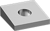
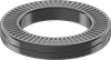
Washer Type Washer Type |
|---|
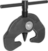
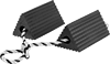
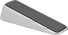
| Leveling for I- Beams | Wedge Lock |