


System of Measurement System of Measurement |
|---|
|
Mount Type Mount Type | Show |
|---|
|
Mount Type Mount Type | Hide |
|---|
Base Material Base Material |
|---|
|
Base Diameter Base Diameter |
|---|
|
|
|
Base Height Base Height |
|---|
|
|
|
DFARS (Defense Acquisition Regulations Supplement) DFARS (Defense AcquisitionRegulations Supplement) |
|---|
Base Shape Base Shape |
|---|
|
RoHS (Restriction of Hazardous Substances) RoHS (Restriction ofHazardous Substances) |
|---|
|
REACH (Registration, Evaluation, Authorization and Restriction of Chemicals) REACH (Registration,Evaluation, Authorization and Restriction of Chemicals) |
|---|
|
Material Material |
|---|
|
Component Component |
|---|
| Mounting Rod Bracket | Sensor Bracket |
Thread Size Thread Size |
|---|
For Rod Orientation For Rod Orientation |
|---|
|
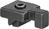
Machine Table Workstops
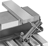
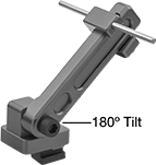
The T-nut base secures the workstop into the slots of a machine table for positioning parts that extend beyond the jaws of your vise. Workstops tilt 180° and have an adjustable stop pin that slides in and out for precise positioning.
T-Slot Nut Base | |||||||||
|---|---|---|---|---|---|---|---|---|---|
| For Slot Wd. | Lg. | Wd. | Ht. | Thread Size | Ht. | Wd. | Features | Each | |
Aluminum | |||||||||
| 5/8" | 5 29/32" | 2 5/16" | 1 1/4" | 1/2"-13 | 11/32" | 1" | Adjustable Stop Pin | 00000000 | 000000 |
Slot-Mount Workstops for Machine Vises
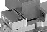
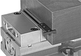
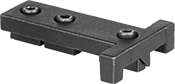
Mount these workstops into slotted vise jaws—they hold workpieces in place and prevent horizontal movement during machining. Tighten them in place with screws for precise positioning. Unlike other workstops, they don’t grip the outside of jaws, so they’re less likely to interfere with your vise.
13/16"-long workstops mount anywhere along the length of a vise jaw.
1-11/16"-long workstops hold work that extends beyond the width of a vise jaw. They must be positioned on the ends of the jaw.
Slip-On Feet
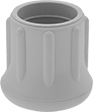

Cover the bottom of furniture legs to protect floors from scratches and wear.
Feet with a reinforced bottom have a metal washer in the base to prevent equipment legs from cutting through the rubber.
![]() For technical drawings and 3-D models, click on a part number.
For technical drawings and 3-D models, click on a part number.
Base | ||||||||
|---|---|---|---|---|---|---|---|---|
| Style | For Leg OD | Dia. | Ht. | Features | Choose a Base Color | Pkg. Qty. | Pkg. | |
Rubber | ||||||||
| 2 | 1/4" | 43/64" | 13/16" | __ | 10 | 0000000 | 00000 | |
| 2 | 1/4" | 43/64" | 13/16" | Reinforced Bottom | 10 | 0000000 | 0000 | |
| 2 | 3/8" | 51/64" | 1 1/8" | __ | 10 | 0000000 | 0000 | |
| 2 | 3/8" | 51/64" | 1 1/8" | Reinforced Bottom | 10 | 0000000 | 0000 | |
| 2 | 1/2" | 61/64" | 1 3/16" | __ | 10 | 0000000 | 0000 | |
| 2 | 1/2" | 61/64" | 1 3/16" | Reinforced Bottom | 10 | 0000000 | 0000 | |
| 2 | 5/8" | 1 1/16" | 1 9/32" | __ | 10 | 0000000 | 0000 | |
| 2 | 5/8" | 1 1/16" | 1 9/32" | Reinforced Bottom | 10 | 0000000 | 0000 | |
| 2 | 3/4" | 1 7/32" | 1 3/8" | __ | 10 | 0000000 | 0000 | |
| 2 | 3/4" | 1 7/32" | 1 3/8" | Reinforced Bottom | 10 | 0000000 | 0000 | |
| 2 | 7/8" | 1 13/32" | 1 1/2" | __ | 10 | 0000000 | 0000 | |
| 2 | 7/8" | 1 13/32" | 1 1/2" | Reinforced Bottom | 10 | 0000000 | 0000 | |
| 2 | 1" | 1 9/16" | 1 9/16" | __ | 10 | 0000000 | 0000 | |
| 2 | 1" | 1 9/16" | 1 9/16" | Reinforced Bottom | 10 | 0000000 | 00000 | |
| 2 | 1 1/8" | 1 21/32" | 1 21/32" | __ | 10 | 0000000 | 0000 | |
| 2 | 1 1/8" | 1 21/32" | 1 21/32" | Reinforced Bottom | 10 | 0000000 | 00000 | |
| 2 | 1 1/4" | 1 13/16" | 1 13/16" | __ | 25 | 0000000 | 00000 | |
| 2 | 1 1/4" | 1 13/16" | 1 13/16" | Reinforced Bottom | 10 | 0000000 | 00000 | |
| 3 | 1/4" | 41/64" | 13/16" | __ | 10 | 0000000 | 0000 | |
| 3 | 1/4" | 41/64" | 13/16" | Reinforced Bottom | 10 | 0000000 | 0000 | |
| 3 | 3/8" | 23/32" | 1" | __ | 10 | 0000000 | 0000 | |
| 3 | 3/8" | 23/32" | 1" | Reinforced Bottom | 10 | 0000000 | 0000 | |
| 3 | 1/2" | 1 1/16" | 1 1/16" | __ | 25 | 0000000 | 00000 | |
| 3 | 1/2" | 1 1/16" | 1 1/16" | Reinforced Bottom | 10 | 0000000 | 0000 | |
| 3 | 5/8" | 1 7/64" | 1 1/16" | __ | 10 | 0000000 | 0000 | |
| 3 | 5/8" | 1 7/64" | 1 1/16" | Reinforced Bottom | 10 | 0000000 | 0000 | |
| 3 | 3/4" | 1 5/32" | 1 7/32" | __ | 10 | 0000000 | 0000 | |
| 3 | 3/4" | 1 5/32" | 1 7/32" | Reinforced Bottom | 10 | 000000 | 0000 | |
| 3 | 7/8" | 1 9/64" | 1 5/16" | __ | 10 | 0000000 | 0000 | |
| 3 | 7/8" | 1 9/64" | 1 5/16" | Reinforced Bottom | 10 | 000000 | 0000 | |
| 3 | 1" | 1 15/32" | 1 1/2" | __ | 10 | 0000000 | 0000 | |
| 3 | 1" | 1 15/32" | 1 1/2" | Reinforced Bottom | 10 | 000000 | 0000 | |
| 3 | 1 1/8" | 1 9/16" | 1 1/2" | __ | 10 | 0000000 | 0000 | |
| 3 | 1 1/8" | 1 9/16" | 1 1/2" | Reinforced Bottom | 10 | 000000 | 00000 | |
| 3 | 1 1/4" | 2" | 1 5/8" | __ | 25 | 0000000 | 00000 | |
| 3 | 1 1/4" | 2" | 1 5/8" | Reinforced Bottom | 10 | 000000 | 00000 | |
| 4 | 9/32" | 1 1/4" | 1 1/8" | __ | Black | 10 | 00000000 | 00000 |
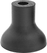
Oil-Resistant Slip-On Feet

Made of neoprene rubber, these feet are a good choice for use in oily environments. Use them to cover the bottom of furniture legs, canes, and crutches to gain traction and protect floors from scratches and wear.
Feet with a reinforced bottom have a metal washer in the base to prevent equipment legs from cutting through the rubber.
![]() For technical drawings and 3-D models, click on a part number.
For technical drawings and 3-D models, click on a part number.
Base | |||||||
|---|---|---|---|---|---|---|---|
| For Leg OD | Dia. | Ht. | Features | Choose a Base Color | Pkg. Qty. | Pkg. | |
Rubber | |||||||
| 3/4" | 1 7/32" | 1 3/8" | __ | 25 | 0000000 | 000000 | |
| 3/4" | 1 7/32" | 1 3/8" | Reinforced Bottom | 10 | 0000000 | 0000 | |
| 1" | 1 9/16" | 1 9/16" | __ | 10 | 0000000 | 0000 | |
| 1" | 1 9/16" | 1 9/16" | Reinforced Bottom | 10 | 0000000 | 00000 | |
| 1 1/4" | 1 13/16" | 1 13/16" | __ | 10 | 0000000 | 00000 | |
| 1 1/4" | 1 13/16" | 1 13/16" | Reinforced Bottom | 5 | 0000000 | 0000 | |
UV-Resistant Slip-On Feet

Great for use outdoors, these feet are EPDM rubber, which withstands exposure to direct sunlight. Use them to cover the bottom of furniture legs, canes, and crutches to gain traction and protect floors from scratches and wear.
Feet with a reinforced bottom have a metal washer in the base to prevent equipment legs from cutting through the rubber.
![]() For technical drawings and 3-D models, click on a part number.
For technical drawings and 3-D models, click on a part number.
Base | |||||||
|---|---|---|---|---|---|---|---|
| For Leg OD | Dia. | Ht. | Features | Choose a Base Color | Pkg. Qty. | Pkg. | |
Rubber | |||||||
| 3/4" | 1 7/32" | 1 3/8" | __ | 25 | 0000000 | 000000 | |
| 3/4" | 1 7/32" | 1 3/8" | Reinforced Bottom | 10 | 0000000 | 0000 | |
| 1" | 1 9/16" | 1 9/16" | __ | 10 | 0000000 | 0000 | |
| 1" | 1 9/16" | 1 9/16" | Reinforced Bottom | 10 | 0000000 | 00000 | |
| 1 1/4" | 1 13/16" | 1 13/16" | __ | 10 | 0000000 | 00000 | |
| 1 1/4" | 1 13/16" | 1 13/16" | Reinforced Bottom | 5 | 0000000 | 0000 | |
Sensor and Reflector Brackets for Conveyors
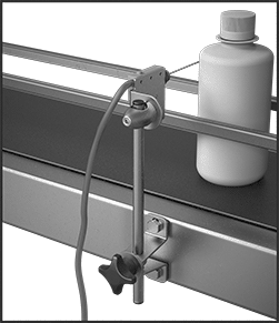
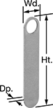
Mount sensors and reflectors on your conveyor frame.
Slide-in brackets attach with a conveyor guide clamp.
Insert a proximity sensor into Style D and G brackets.
![]() For technical drawings and 3-D models, click on a part number.
For technical drawings and 3-D models, click on a part number.
Mounting Rod Brackets for Conveyors
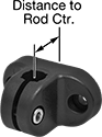
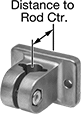

Brackets mount to the frame of a conveyor to hold mounting rods.
![]() For technical drawings and 3-D models, click on a part number.
For technical drawings and 3-D models, click on a part number.
Mounting Hole | |||||||||
|---|---|---|---|---|---|---|---|---|---|
| Style | For Rod Dia. | Wd. | Distance to Rod Ctr. | Mounting Fasteners Included | Dia. | Ctr.-to-Ctr. | For T-Slot Wd., mm | Each | |
Plastic | |||||||||
| B | 12mm | 1.57" | 0.79" | Yes | 0.250" | 1.57" | 8 | 00000000 | 000000 |
Aluminum | |||||||||
| C | 1/2" | 1.57" | 0.71" | Yes | 0.220" | 1.50" | 8 | 00000000 | 00000 |
| C | 12mm | 1.57" | 0.71" | Yes | 0.220" | 1.50" | 8 | 00000000 | 00000 |
| D | 1/2" | 0.62" | 0.27" | Yes | 0.200" | 1.06" | 8 | 00000000 | 00000 |