


About Selecting Shock Absorbers
To select the best shock absorber for your application, you need to find the energy capacity your application requires. Use this formula to calculate the energy capacity required to stop a horizontal-moving load. For example, if you have a 250-lb. load moving at 25 inches per second, your calculation is (250 lbs. ÷ 772) × 252 = 202.4 in.-lbs. energy capacity.
Note: Choose a shock absorber with a higher energy capacity than you calculated. Factors such as driving force or an inclined surface will increase the energy capacity required.
Energy Capacity (in.-lbs.) = (Weight, lbs./772) × Velocity2 (in. per second)
Light Duty Adjustable Shock Absorbers
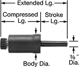
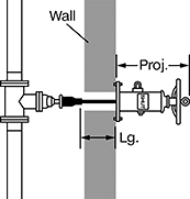
Also known as snubbers, use these shock absorbers in low-load, high-cycle applications. They counteract the energy of moving objects to prevent damage to equipment and material. Turn the knob to change deceleration to suit varying loads and speeds. Through-wall shock absorbers have a stud and nut under the removable knob for mounting through a panel or bracket.
Rod | Mount. Stud | |||||||||||
|---|---|---|---|---|---|---|---|---|---|---|---|---|
| Energy Cap., in.-lbs. | Max. Cycles per Minute | Stroke Lg. | Extended Lg. | Compressed Lg. | Body Dia. | Body Material | Dia. | Material | Thread Size | Lg. | Each | |
Variable Adjustment | ||||||||||||
| 4 | 600 | 1.1" | 4.32" | 2.99" | 1.01" | Rubber-Coated Borosilicate Glass | 0.375" | Urethane | 3/8"-32 | 1/8" | 0000000 | 000000 |
| 9 | 330 | 1.3" | 4.15" | 2.62" | 1.35" | Rubber-Coated Borosilicate Glass | 0.375" | Urethane | 3/8"-32 | 1/8" | 0000000 | 00000 |
Fire Post Indicators
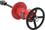
Open and close water supply valves for fire systems that are buried underground or in a wall. FM approved for fire suppression and protection applications, these post indicators are often used as part of a post indicator valve (PIV) system. A message on their body lets you know if the valve is open or shut.
Install and maintain them according to National Fire Protection Association (NFPA) standards.

For Drive | |||||||||||||||
|---|---|---|---|---|---|---|---|---|---|---|---|---|---|---|---|
| Flange OD | Bolt Circle Dia. | No. of Bolt Holes | Bolt Hole Dia. | Bolts Included | Dia. | Projection | Lg. | Style | Size | Body Material | Color | Message | Specifications Met | Each | |
Wheel Handle for Gate On/Off Valves with Nonrising Stem | |||||||||||||||
| 12" | 10 1/2" | 4 | 11/16" | No | 6 1/4" | 20" | 16" | External Square | 2" | Epoxy-Coated Cast Iron | Red | Open, Shut | FM Approved, UL Listed | 00000000 | 0000000 |