


Selecting Clamps Using Pipe, Conduit, or Tubing Trade Size
More
Magnetic Vibration-Damping Routing Clamps
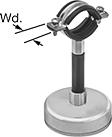
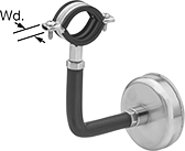
Temporarily route material across duct, racks, machinery, and other ferrous surfaces. Clamps fit tightly around pressurized lines in hydraulic systems to lessen vibration. Rubber cushions reduce wear from clamp edges and protect lines from corrosion caused by metal-to-metal contact. All clamps are zinc-plated steel for good corrosion resistance.
![]() For technical drawings and 3-D models, click on a part number.
For technical drawings and 3-D models, click on a part number.
ID | ||||||||||||
|---|---|---|---|---|---|---|---|---|---|---|---|---|
| Inch | Metric, mm | Cushion Color | Capacity, lbs. | Lg. | Wd. | Ht. | Magnet Dia. | Clamping Fasteners Included | Temp. Range, °F | For Use Outdoors | Each | |
Zinc-Plated Steel | ||||||||||||
Straight | ||||||||||||
| 9/16"-3/4" | 14-19 | Black | 75 | 2 1/2" | 13/16" | 2 3/8" | 2 1/2" | Yes | 0° to 245° | Yes | 0000000 | 000000 |
| 9/16"-3/4" | 14-19 | Black | 75 | 2 1/2" | 13/16" | 5 1/8" | 2 1/2" | Yes | 0° to 245° | Yes | 0000000 | 00000 |
| 9/16"-3/4" | 14-19 | Black | 130 | 2 1/2" | 13/16" | 2 3/4" | 3 1/8" | Yes | 0° to 245° | Yes | 0000000 | 00000 |
| 13/16"-1" | 21-25 | Black | 75 | 2 5/8" | 13/16" | 2 9/16" | 2 1/2" | Yes | 0° to 245° | Yes | 0000000 | 00000 |
| 13/16"-1" | 21-25 | Black | 75 | 2 5/8" | 13/16" | 5 11/16" | 2 1/2" | Yes | 0° to 245° | Yes | 0000000 | 00000 |
| 13/16"-1" | 21-25 | Black | 130 | 2 5/8" | 13/16" | 2 15/16" | 3 1/8" | Yes | 0° to 245° | Yes | 0000000 | 00000 |
| 1"-1 1/4" | 25-32 | Black | 75 | 2 3/4" | 13/16" | 2 3/4" | 2 1/2" | Yes | 0° to 245° | Yes | 0000000 | 00000 |
| 1"-1 1/4" | 25-32 | Black | 130 | 2 3/4" | 13/16" | 3 1/8" | 3 1/8" | Yes | 0° to 245° | Yes | 0000000 | 00000 |
| 1"-1 1/4" | 25-32 | Black | 130 | 2 3/4" | 13/16" | 5 7/8" | 3 1/8" | Yes | 0° to 245° | Yes | 0000000 | 00000 |
| 1 1/4"-1 7/16" | 32-37 | Black | 75 | 3" | 13/16" | 2 15/16" | 2 1/2" | Yes | 0° to 245° | Yes | 0000000 | 00000 |
| 1 1/4"-1 7/16" | 32-37 | Black | 130 | 3" | 13/16" | 3 3/8" | 3 1/8" | Yes | 0° to 245° | Yes | 0000000 | 00000 |
| 1 1/4"-1 7/16" | 32-37 | Black | 130 | 3" | 13/16" | 6 5/16" | 3 1/8" | Yes | 0° to 245° | Yes | 0000000 | 00000 |
90° Angle | ||||||||||||
| 9/16"-3/4" | 14-19 | Black | 75 | 6 1/2" | 13/16" | 5 11/16" | 2 1/2" | Yes | 0° to 245° | Yes | 0000000 | 00000 |
| 13/16"-1" | 21-25 | Black | 75 | 6 11/16" | 13/16" | 5 7/8" | 2 1/2" | Yes | 0° to 245° | Yes | 0000000 | 00000 |
| 1"-1 1/4" | 25-32 | Black | 130 | 8 1/16" | 13/16" | 6 1/2" | 3 1/8" | Yes | 0° to 245° | Yes | 0000000 | 00000 |
| 1 1/4"-1 7/16" | 32-37 | Black | 130 | 8 1/4" | 13/16" | 6 7/8" | 3 1/8" | Yes | 0° to 245° | Yes | 0000000 | 00000 |
Routing J-Hooks
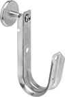
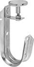
Route bundles of wire and cable through a single hook. A wide opening allows access for installation, adjustment, and removal.
Style D and style E hooks have magnets for a temporary hold on steel and iron surfaces.
![]() For technical drawings and 3-D models, click on a part number.
For technical drawings and 3-D models, click on a part number.
Overall | ||||||||||
|---|---|---|---|---|---|---|---|---|---|---|
| Style | For Max. Bundle Dia. | Material | Temp. Range, °F | Capacity, lbs. | Lg. | Wd. | Ht. | Specifications Met | Each | |
Magnetic | ||||||||||
| D | 3/4" | Galvanized Steel | -40° to 570° | 15 | 1 1/16" | 7/8" | 3 5/8" | UL Listed | 0000000 | 00000 |
| D | 1 5/16" | Galvanized Steel | -40° to 570° | 15 | 2" | 1 3/8" | 4 7/8" | UL Listed | 0000000 | 0000 |
| D | 2" | Galvanized Steel | -40° to 570° | 15 | 2 1/2" | 1 3/8" | 5 3/16" | UL Listed | 0000000 | 00000 |
| E | 3/4" | Galvanized Steel | -40° to 570° | 15 | 1 1/16" | 7/8" | 4 3/4" | UL Listed | 0000000 | 00000 |
| E | 1 5/16" | Galvanized Steel | -40° to 570° | 15 | 2" | 1 3/8" | 4 5/8" | UL Listed | 0000000 | 00000 |
| E | 2" | Galvanized Steel | -40° to 570° | 15 | 2 1/2" | 1 3/8" | 5 1/4" | UL Listed | 0000000 | 00000 |
Magnetic Routing Ring Bases
Temporarily mount routing rings and other threaded components to steel and iron surfaces.
![]() For technical drawings and 3-D models, click on a part number.
For technical drawings and 3-D models, click on a part number.
Routing Rings
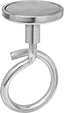
Also known as bridle rings, routing rings have an open-eye design that allows you to quickly install wire and cable. Magnetic routing rings provide a temporary hold on steel and iron surfaces.
![]() For technical drawings and 3-D models, click on a part number.
For technical drawings and 3-D models, click on a part number.
Spring Clamps with Flexible Arm
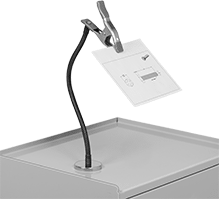
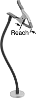
Attached to an arm you can flex into position, these clamps hold objects such as a flashlight, tool, or instructions. Squeeze the handles to open the clamp; release and the spring holds it tightly in place.
Magnetic-mount clamp attaches to steel surfaces.
![]() For technical drawings and 3-D models, click on a part number.
For technical drawings and 3-D models, click on a part number.
Opening | Jaw | ||||||||
|---|---|---|---|---|---|---|---|---|---|
| Max. | Min. | Reach | Holding Capacity | Wd. | Material | Overall Lg. | Mount Type | Each | |
Steel Body | |||||||||
| 2" | 0" | 2 5/8" | Not Rated | 1" | Rubber | 22" | Magnetic | 00000000 | 000000 |
Ball-Grip Positioning Arms
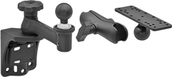
Ball-and-socket connections allow 360° positioning. Choose a complete arm or select a base, connectors, and a plate, grip, holder, or tray to build a complete arm.
![]() For technical drawings and 3-D models, click on a part number.
For technical drawings and 3-D models, click on a part number.

| Mount. Location | Ht. | Ball Dia. | Max. Load Capacity, lbs. | Material | Ball Material | Base Dia. | Each | |
| Bench, Wall | 2 1/4" | 1 1/2" | 0.5 | Aluminum | Rubber | 2 1/2" | 0000000 | 000000 |