


Filter by
Actuator Style
Switch Starting Position
Actuator Height
Electrical Connection Type
Wire Connection

Switch Action
Housing Material
U.S.–Mexico–Canada Agreement (USMCA) Qualifying
Export Control Classification Number (ECCN)
DFARS Specialty Metals
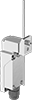
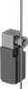
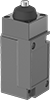
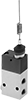
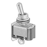
Limit Switches