


Filter by
Panel Cutout Diameter


Switch Action
Push-Button Style


Actuator Style

Illumination
Wire Connection
Mounting Location
Switch Starting Position
Switch Type
DFARS Specialty Metals
Export Control Classification Number (ECCN)

About Electrical Switches
Choose a switch with the right trigger type, number of inputs, and control functions to power your equipment.
16 mm Panel-Mount Push-Button Switches
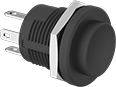 |  |
Tab Wire Connection | Wire Leads Connection |
Choose an actuator and contact block to build your own switch. You get exactly the actuator style and contact configuration you need. If one part wears out, replace just that component instead of the entire switch. All switches are rated NEMA 4, 13, and IP65 for protection from washdowns and oil/coolant spray.
No. of Circuits Controlled | Switch Starting Position | Switch Action | No. of Terminals | Switch Designation | Switching Current @ Voltage | Dia. | For Max. Panel Thk. | Dp. Behind Panel | For Max. No. of Contact Blocks | Actuator Color | Each | |||
|---|---|---|---|---|---|---|---|---|---|---|---|---|---|---|
Plastic Actuator Base with Tab Wire Connection—Not Illuminated (250V AC/30V DC Maximum Voltage) | ||||||||||||||
Projecting | ||||||||||||||
| 1 | 1 Off or 1 On | Momentary | 3 | SPDT | 3 amp @ 120V AC, 3 amp @ 24V DC | 13/16" | 1/4" | 13/16" | 1 | Black | 6886K111 | 000000 | ||
Plastic Actuator Base with Wire Lead Connection—Not Illuminated (250V AC/30V DC Maximum Voltage) | ||||||||||||||
Projecting | ||||||||||||||
| 1 | 1 Off or 1 On | Momentary | 3 | SPDT | 3 amp @ 120V AC, 3 amp @ 24V DC | 13/16" | 1/4" | 13/16" | 1 | Black | 6886K36 | 00000 | ||
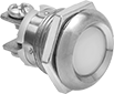
Flush-Mount 16 mm Panel-Mount Push-Button Switches
 |
Because these switches mount flush against a panel, they're easy to clean and hard to damage.
Note: Illuminated switches include a bulb. If wiring the switch and the bulb to the same circuit, the circuit voltage must not exceed bulb voltage.
Quick-Disconnect-Terminal Wire Connection—Switches with quick-disconnect terminals are rated IP40 for parts behind the panel, and IP67 for the front of the panel.
No. of Circuits Controlled | Switch Starting Position | Switch Action | No. of Terminals | Switch Designation | Switching Current @ Voltage | Max. Voltage | Dia. | Dp. Behind Panel | For Max. No. of Contact Blocks | Quick-Disconnect Tab Wd. | Enclosure Rating | Choose an Actuator Color | Each | |||
|---|---|---|---|---|---|---|---|---|---|---|---|---|---|---|---|---|
Plastic Actuator Base with Tab Wire Connection—Not Illuminated | ||||||||||||||||
| 1 | 1 Off | Momentary | 4 | SPST-NO | 0.1 amp @ 42V AC/42V DC | 42V AC 42V DC | 3/4" | 1 3/16" | 1 | — | IP40 | Black, Green, Red, Yellow | 6886K2 | 000000 | ||
Plastic Actuator Base with Tab Wire Connection—Illuminated | ||||||||||||||||
| 1 | 1 Off | Momentary | 4 | SPST-NO | 0.1 amp @ 42V AC/42V DC | 42V AC 42V DC | 3/4" | 1 3/16" | 1 | — | IP40 | Green, Red, Yellow | 6886K91 | 00000 | ||
Plastic Actuator Base with Tab Wire Connection and Push Reset—Not Illuminated | ||||||||||||||||
| 1 | 1 Off | Maintained | 4 | SPST-NO | 0.1 amp @ 42V AC/42V DC | 42V AC 42V DC | 3/4" | 1 3/16" | 1 | — | IP40 | Black, Green, Red, Yellow | 6886K1 | 00000 | ||
Plastic Actuator Base with Tab Wire Connection and Push Reset—Illuminated | ||||||||||||||||
| 1 | 1 Off | Maintained | 4 | SPST-NO | 0.1 amp @ 42V AC/42V DC | 42V AC 42V DC | 3/4" | 1 3/16" | 1 | — | IP40 | Green, Red, Yellow | 6886K93 | 00000 | ||
Stainless Steel Actuator Base with Quick-Disconnect-Terminal Wire Connection—Not Illuminated | ||||||||||||||||
| 1 | 1 Off or 1 On | Momentary | 3 | SPDT | 5 amp @ 250V AC | 250V AC | 3/4" | 1 5/16" | — | 0.11" | IK08, IP40, IP67 | — | 6023T15 | 00000 | ||
Low-Voltage 16 mm Panel-Mount Push-Button Doorbell Switches
 | 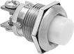 |  |
Flush with Hex Nut Mount | Projecting with Hex Nut Mount | Projecting Snap In |
No. of Circuits Controlled | Switch Starting Position | Switch Action | No. of Terminals | Switch Designation | Actuator Color | Switching Current @ Voltage | Max. Voltage | Dia. | Dp. Behind Panel | Each | |||
|---|---|---|---|---|---|---|---|---|---|---|---|---|---|
Metal Actuator Base with Screw-Terminal Wire Connection | |||||||||||||
Flush with Hex Nut Mount | |||||||||||||
| 1 | 1 Off | Momentary | 2 | SPST-NO | White | 10 amp @ 24V AC, 2 amp @ 24V DC | 48V AC 48V DC | 3/4" | 7/8" | 69755K62 | 000000 | ||
Projecting with Hex Nut Mount | |||||||||||||
| 1 | 1 Off | Momentary | 2 | SPST-NO | White | 10 amp @ 24V AC, 2 amp @ 24V DC | 48V AC 48V DC | 3/4" | 15/16" | 69755K63 | 00000 | ||
| 1 | 1 Off | Momentary | 2 | SPST-NO | Black | 10 amp @ 24V AC, 2 amp @ 24V DC | 48V AC 48V DC | 3/4" | 15/16" | 69755K202 | 00000 | ||
Projecting Snap In | |||||||||||||
| 1 | 1 Off | Momentary | 2 | SPST-NO | White | 3 amp @ 30V AC/30V DC | 30V AC 30V DC | 3/4" | 13/16" | 69755K31 | 0000 | ||
| 1 | 1 Off | Momentary | 2 | SPST-NO | Black | 10 amp @ 24V AC, 2 amp @ 24V DC | 48V AC 48V DC | 3/4" | 15/16" | 69755K201 | 00000 | ||
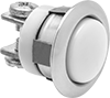
16 mm Panel-Mount Build-Your-Own Plastic Push-Button Switches
Push-Button Actuators
 |  |  |
Round Flush Push Button with Push Reset | Rectangle Flush Push Button with Push Reset | Square Flush Push Button with Push Reset |
Switch Action | Switching Current @ Voltage | Max. Voltage, V AC | Dia. | Ht. | Wd. | For Max. No. of Contact Blocks | Enclosure Rating | Certification | Choose an Actuator Color | Each | |||
|---|---|---|---|---|---|---|---|---|---|---|---|---|---|
Round Flush Push Button with Push Reset | |||||||||||||
| Momentary, Maintained | 2.5 amp @ 125V AC, 6 amp @ 24V DC | 250 | 11/16" | — | — | 1 | IP65, NEMA 4, NEMA 13 | CE Marked, CSA Certified, UL Recognized Component | Black, Green, Red, White, Yellow | 65645K14 | 000000 | ||
Rectangle Flush Push Button with Push Reset | |||||||||||||
| Momentary, Maintained | 2.5 amp @ 125V AC, 6 amp @ 24V DC | 250 | — | 15/16" | 11/16" | 1 | IP65, NEMA 4, NEMA 13 | CE Marked, CSA Certified, UL Recognized Component | Black, Green, Red, White, Yellow | 65645K12 | 00000 | ||
Square Flush Push Button with Push Reset | |||||||||||||
| Momentary, Maintained | 2.5 amp @ 125V AC, 6 amp @ 24V DC | 250 | — | 11/16" | 11/16" | 1 | IP65, NEMA 4, NEMA 13 | CE Marked, CSA Certified, UL Recognized Component | Black, Green, Red, White, Yellow | 65645K13 | 00000 | ||
| Momentary, Maintained | 2.5 amp @ 125V AC, 6 amp @ 24V DC | 250 | — | 15/16" | 15/16" | 1 | IP65, NEMA 4, NEMA 13 | CE Marked, CSA Certified, UL Recognized Component | Black, Green, Red, White, Yellow | 65645K11 | 00000 | ||
16 mm Panel-Mount Lever Switches
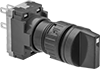 |
Avoid accidental actuation—these switches won’t turn on or off until you grip and twist the lever. Install in a 16 mm dia. cutout. To help users identify switches without having to read labels, use differently colored switches for different tasks. Rated NEMA 4, 13, and IP65, all are protected from washdowns and oil/coolant spraying.
3 Positions—Three-position switches are off in the center position.
Lever Lg. | No. of Circuits Controlled | Switch Starting Position | Switch Action | No. of Terminals | Switch Designation | Switching Current @ Voltage | Max. Voltage | Dia. | Dp. Behind Panel | For Max. No. of Contact Blocks | Quick-Disconnect Tab Wd. | Choose an Actuator Color | Each | |||
|---|---|---|---|---|---|---|---|---|---|---|---|---|---|---|---|---|
2 Positions with Plastic Actuator Base | ||||||||||||||||
Quick-Disconnect-Terminal Wire Connection | ||||||||||||||||
| 9/16" | 1 | 1 Off | Momentary | 4 | SPST-NO | 2.5 amp @ 125V AC, 6 amp @ 24V DC | 250V DC 250V AC | 11/16" | 1 11/16" | 3 | 0.11" | Black, Green, Red, White, Yellow | 65645K31 | 000000 | ||
| 9/16" | 1 | 1 Off | Maintained | 4 | SPST-NO | 2.5 amp @ 125V AC, 6 amp @ 24V DC | 250V DC 250V AC | 11/16" | 1 11/16" | 3 | 0.11" | Black, Green, Red, White, Yellow | 65645K32 | 00000 | ||
| 9/16" | 2 | 2 Off | Maintained | 6 | DPST-NO | 2.5 amp @ 125V AC, 6 amp @ 24V DC | 250V DC 250V AC | 11/16" | 1 11/16" | 3 | 0.11" | Black, Green, Red, White, Yellow | 65645K33 | 00000 | ||
3 Positions with Plastic Actuator Base | ||||||||||||||||
Quick-Disconnect-Terminal Wire Connection | ||||||||||||||||
| 9/16" | 2 | 2 Off | Maintained | 6 | DPST-NO | 2.5 amp @ 125V AC, 6 amp @ 24V DC | 250V DC 250V AC | 11/16" | 1 11/16" | 2 | 0.11" | Black, Green, Red, White, Yellow | 65645K35 | 00000 | ||
16 mm Panel-Mount Push-Button-Actuator Emergency Stop Switches
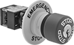 | 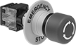 |
Key Reset | Turn Reset |
Immediately cut power with a single push. These switches meet EN 418 for compliance with European machine directives for emergency stop applications. They're rated NEMA 4, 13, and IP65 for protection from washdowns and oil/coolant spraying.
Key Reset—Key reset switches are keyed alike, so if you buy multiple switches they will all reset with the same key.
Number of Circuits Controlled | Switch Starting Position | Switch Action | Actuator Style | Actuator Color | Switch Designation | Number of Terminals | Switching Current @ Voltage | Max. Voltage, V AC | Dia. | Dp. Behind Panel | For Max. No. of Contact Blocks | Enclosure Rating | No. of Keys Included | Each | |||
|---|---|---|---|---|---|---|---|---|---|---|---|---|---|---|---|---|---|
Plastic Actuator With Screw-Terminal Wire Connection | |||||||||||||||||
Key Reset | |||||||||||||||||
| 1 | 1 On | Maintained | Push Button | Red | SPST-NC | 2 | 2.5 amp @ 125V AC 6 amp @ 24V DC | 250 | 1 1/16" | 1 11/16" | 1 | IP65 NEMA 4 NEMA 13 | 2 | 65645K62 | 0000000 | ||
Turn Reset | |||||||||||||||||
| 1 | 1 On | Maintained | Push Button | Red | SPST-NC | 2 | 2.5 amp @ 125V AC 6 amp @ 24V DC | 250 | 1 1/16" | 1 11/16" | 1 | IP65 NEMA 4 NEMA 13 | — | 65645K61 | 000000 | ||
Multiple-Position Single-Action Air Directional Control Valves
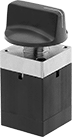 |
Control six different outputs from a single source of airflow. These valves have one inlet port and six outlet ports. Push in and rotate the dial to move between outlet ports and send airflow to a different output. Also known as 3-way valves, they create one action, such as extending a cylinder. They direct airflow from the inlet to your equipment and exhaust return airflow to create motion. Return actuation is by hand, so the chosen output remains actuated until you move the dial to another position. Air pressure exhausts to the atmosphere once a new position is selected.
Flow Coefficient (Cv)—Flow coefficient (Cv) indicates how much airflow can pass through a valve.
Overall | |||||||||||||||||
|---|---|---|---|---|---|---|---|---|---|---|---|---|---|---|---|---|---|
No. of Flow Ports | Inlet Size | Outlet Size | Max. Flow Rate @ 100 psi, scfm | Flow Coefficient (Cv) | Pressure Range, psi | Vacuum Rating | Lg. | Wd. | Ht. | Mount Type | For Panel Cutout Dia. | Mounting Fasteners Included | Mounting Hole Dia. | Each | |||
Threaded Female Inlet x Threaded Female Outlet | |||||||||||||||||
Hand Return | |||||||||||||||||
| 7 | 10-32 UNF | 10-32 UNF | 7.5 | 0.09 | 0 to 125 | Not Rated | 1 1/2" | 1 1/2" | 2 3/4" | Panel, Screw In | 5/8" | Yes | 0.86" | 3020N11 | 0000000 | ||
16 mm Panel-Mount Key Switches
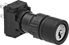 |
Limit access to sensitive equipment—these switches require a key to actuate. Rated NEMA 4, 13, and IP65, they're protected from washdowns and oil/coolant spraying. All are keyed alike, so they open with the same key.
No. of Circuits Controlled | Switch Starting Position | Switch Action | No. of Terminals | Switch Designation | Actuator Color | Switching Current @ Voltage | Max. Voltage | Dia. | Dp. Behind Panel | For Max. No. of Contact Blocks | Quick-Disconnect Tab Wd. | No. of Keys Included | Key Removal Position | Enclosure Rating | Each | |||
|---|---|---|---|---|---|---|---|---|---|---|---|---|---|---|---|---|---|---|
2 Positions with Plastic Actuator Base | ||||||||||||||||||
Keyed Alike with Quick-Disconnect-Terminal Wire Connection | ||||||||||||||||||
| 1 | 1 Off | Momentary | 4 | SPST-NO | Black | 2.5 amp @ 125V AC, 6 amp @ 24V DC | 250V AC 250V DC | 11/16" | 1 11/16" | 3 | 0.11" | 2 | Center | NEMA 4, NEMA 13, IP65 | 65645K41 | 000000 | ||
| 1 | 1 Off | Maintained | 4 | SPST-NO | Black | 2.5 amp @ 125V AC, 6 amp @ 24V DC | 250V AC 250V DC | 11/16" | 1 11/16" | 3 | 0.11" | 2 | Center, Right | NEMA 4, NEMA 13, IP65 | 65645K42 | 00000 | ||
| 2 | 2 Off | Maintained | 6 | DPST-NO | Black | 2.5 amp @ 125V AC, 6 amp @ 24V DC | 250V AC 250V DC | 11/16" | 1 11/16" | 3 | 0.11" | 2 | Center, Right | NEMA 4, NEMA 13, IP65 | 65645K43 | 00000 | ||
3 Positions with Plastic Actuator Base | ||||||||||||||||||
Keyed Alike with Quick-Disconnect-Terminal Wire Connection | ||||||||||||||||||
| 2 | 2 Off | Momentary | 6 | DPST-NO | Black | 2.5 amp @ 125V AC, 6 amp @ 24V DC | 250V AC 250V DC | 11/16" | 1 11/16" | 2 | 0.11" | 2 | Center | NEMA 4, NEMA 13, IP65 | 65645K44 | 00000 | ||
| 2 | 2 Off | Maintained | 6 | DPST-NO | Black | 2.5 amp @ 125V AC, 6 amp @ 24V DC | 250V AC 250V DC | 11/16" | 1 11/16" | 2 | 0.11" | 2 | Center, Left, Right | NEMA 4, NEMA 13, IP65 | 65645K45 | 00000 | ||
Two-Speed Two-Action Air Directional Control Valves with Exhausting Shut-Off
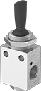 |
Style A |
In the off position, these valves exhaust all air pressure, allowing the equipment to return to the neutral position. Often used to extend and then retract a cylinder at different speeds, they create two actions and have two exhaust ports, which allows you to control the speed of each action by attaching a flow control valve to each exhaust port. They direct airflow from the inlet to your equipment and exhaust return airflow to create motion. Valves without an exhaust connection exhaust air to the atmosphere. Also known as 4-way and 5/3 exhaust center valves.
Hand Return—Valves with hand return actuation stay actuated and return to their original position only when you move the actuator again.
Flow Coefficient (Cv)—Flow coefficient (Cv) is a measurement that indicates how much airflow can pass through a valve. When selecting between valves with the same port size, choose the valve with the higher flow coefficient to ensure it provides enough airflow to operate your system.
Overall | ||||||||||||||||||
|---|---|---|---|---|---|---|---|---|---|---|---|---|---|---|---|---|---|---|
Style | No. of Flow Ports | Inlet Size | Outlet Size | Max. Flow Rate @ 100 psi, scfm | Flow Coefficient (Cv) | Pressure Range, psi | Vacuum Rating | Lg. | Wd. | Ht. | Mount Type | For Panel Cutout Dia. | Mounting Fasteners Included | Mounting Hole Dia. | Each | |||
Threaded Female Inlet x Threaded Female Outlet | ||||||||||||||||||
Hand Return | ||||||||||||||||||
| A | 5 | 1/8 NPT | 1/8 NPT | 7.5 | 0.133 | 0 to 150 | Not Rated | 7/8" | 5/8" | 2 1/2" | Panel, Screw In | 5/8" | Yes | 0.17" | 62475K46 | 000000 | ||
| A | 5 | 10-32 UNF | 10-32 UNF | 7.5 | 0.133 | 0 to 150 | Not Rated | 7/8" | 5/8" | 2 1/2" | Panel, Screw In | 5/8" | Yes | 0.17" | 62475K45 | 00000 | ||
Two-Speed Two-Action Air Directional Control Valves
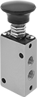 |
Style L |
Often used to extend and then retract a cylinder at different speeds, these valves create two actions and have two exhaust ports. They direct airflow from the inlet to your equipment and exhaust return airflow to create motion. Also known as 4-way and 5/2 valves.
Hand Return—Valves with hand return actuation stay actuated and return to their original position only when you move the actuator again.
Exhaust Connection—Valves with threaded exhaust connection type allow you to control the speed of each action by attaching a flow control valve to each exhaust port. Valves with no exhaust connection type exhaust air to the atmosphere.
Flow Coefficient (Cv)—Flow coefficient (Cv) is a measurement that indicates how much airflow can pass through a valve. When selecting between valves with the same port size, choose the valve with the higher flow coefficient to ensure it provides enough airflow to operate your system.
Overall | |||||||||||||||||||
|---|---|---|---|---|---|---|---|---|---|---|---|---|---|---|---|---|---|---|---|
Style | No. of Flow Ports | Inlet Size | Outlet Size | Exhaust Connection | Max. Flow Rate @ 100 psi, scfm | Flow Coefficient (Cv) | Pressure Range, psi | Vacuum Rating | Lg. | Wd. | Ht. | Mount Type | For Panel Cutout Dia. | Mounting Fasteners Included | Mounting Hole Dia. | Each | |||
Threaded Female Inlet x Threaded Female Outlet | |||||||||||||||||||
Hand Return | |||||||||||||||||||
| L | 5 | 1/8 NPT | 1/8 NPT | Threaded | 25 | 0.8 | 0 to 120 | Not Rated | 7/8" | 1 3/8" | 3 7/8" | Panel, Screw In | 5/8" | No | 0.13" | 61345K13 | 000000 | ||
Labels for Emergency Stop Switches
 |
Without Keyway |
For Panel Cutout Dia. | Dia. | Color (Message Color) | Material | Mount Type | Each | |||
|---|---|---|---|---|---|---|---|---|
Without Keyway | ||||||||
| 16 mm/5/8" | 2 1/2" | Yellow (Black) | Polypropylene | Adhesive Back | 6676N111 | 00000 | ||
Create-Your-Own Push/Pull Mechanical Control Cables
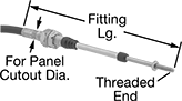 |
Panel Mount |
Pair these cables with a knob or lever (not included) to operate valves, throttle controls, and HVAC damper controls from a distance. They're flexible for weaving around obstructions.
Panel Mount—Panel-mount cables are also known as bulkhead mount cables. They have threaded fittings with hex nuts and washers at each end for mounting through a panel.
Thread | Dynamic Load Cap., lb. | Panel Mount | ||||||||||||
|---|---|---|---|---|---|---|---|---|---|---|---|---|---|---|
Size | Lg. | Overall Lg., ft. | Max. Stroke Lg. | Push | Pull | Bend Radius | Fitting Material | Temp. Range, ° F | For Panel Cutout Dia. | Fitting Lg. | Each | |||
Stainless Steel Cable Core with Plastic Cover | ||||||||||||||
| 1/4"-28 | 1" | 3 | 3" | 75 | 75 | 6" | Zinc-Plated Steel | -65 to 225 | 5/8" | 9 5/8" | 3125K515 | 0000000 | ||
| 1/4"-28 | 1" | 3 | 4" | 65 | 65 | 6" | Zinc-Plated Steel | -65 to 225 | 5/8" | 11 1/8" | 3125K519 | 000000 | ||
| 1/4"-28 | 1" | 6 | 3" | 75 | 75 | 6" | Zinc-Plated Steel | -65 to 225 | 5/8" | 9 5/8" | 3125K517 | 000000 | ||
| 1/4"-28 | 1" | 6 | 4" | 65 | 65 | 6" | Zinc-Plated Steel | -65 to 225 | 5/8" | 11 1/8" | 3125K522 | 000000 | ||
| 1/4"-28 | 1" | 6 | 6" | 60 | 60 | 6" | Zinc-Plated Steel | -65 to 225 | 5/8" | 14 1/8" | 3125K526 | 000000 | ||
Low-Friction Create-Your-Own Push/Pull Mechanical Control Cables
|
Panel Mount |
A splined core limits contact points on the cable’s liner, so the core slides back and forth smoothly and keeps the cable from twisting. Pair these cables with a knob or lever (not included) to operate valves, throttle controls, and HVAC damper controls from a distance. They're flexible for weaving around obstructions.
Panel Mount—Panel-mount cables are also known as bulkhead mount cables. They have threaded fittings with hex nuts and washers at each end for mounting through a panel.
Thread | Dynamic Load Cap. | Panel Mount | ||||||||||||
|---|---|---|---|---|---|---|---|---|---|---|---|---|---|---|
Size | Lg. | Overall Lg., ft. | Max. Stroke Lg. | Push | Pull | Bend Radius | Fitting Material | Temp. Range, ° F | For Panel Cutout Dia. | Fitting Lg. | Each | |||
Steel Cable Core with Plastic Cover | ||||||||||||||
| 1/4"-28 | 1" | 3 | 3" | 130 lb. | 170 lb. | 8" | Zinc-Plated Steel | -40 to 210 | 5/8" | 9 25/64" | 3125K89 | 000000 | ||
| 1/4"-28 | 1" | 3 | 4" | Not Rated | Not Rated | 8" | Zinc-Plated Steel | -65 to 225 | 5/8" | 10.13" | 1338K313 | 00000 | ||
| 1/4"-28 | 1" | 4 | 3" | 130 lb. | 170 lb. | 8" | Zinc-Plated Steel | -40 to 210 | 5/8" | 9 25/64" | 1338K21 | 000000 | ||
| 1/4"-28 | 1" | 4 | 4" | Not Rated | Not Rated | 8" | Zinc-Plated Steel | -65 to 225 | 5/8" | 10.13" | 1338K314 | 000000 | ||
| 1/4"-28 | 1" | 6 | 2" | 150 lb. | 170 lb. | 8" | Zinc-Plated Steel | -40 to 210 | 5/8" | 7 57/64" | 3125K93 | 000000 | ||
| 1/4"-28 | 1" | 6 | 3" | 130 lb. | 170 lb. | 8" | Zinc-Plated Steel | -40 to 210 | 5/8" | 9 25/64" | 1338K22 | 000000 | ||
| 1/4"-28 | 1" | 6 | 4" | 110 lb. | 170 lb. | 8" | Zinc-Plated Steel | -40 to 210 | 5/8" | 10 57/64" | 3125K95 | 000000 | ||
| 1/4"-28 | 1" | 15 | 4" | 110 lb. | 170 lb. | 8" | Zinc-Plated Steel | -40 to 210 | 5/8" | 10 57/64" | 3125K104 | 000000 | ||
 |
External Spring |
For Thread Size | Material | Relubrication | Includes | Each | ||
|---|---|---|---|---|---|---|
| 1/4"-28 | Zinc-Plated Carbon Steel | Required | External Spring | 6058K32 | 00000 |
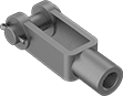 |
Clevis Pin Cotter Pin |
For Thread Size | Material | Includes | Each | ||
|---|---|---|---|---|---|
| 1/4"-28 | Carbon Steel | Clevis Pin, Cotter Pin | 6071K12 | 00000 |
Dynamic Load Cap., lb. | |||||||||
|---|---|---|---|---|---|---|---|---|---|
For Thread Size | For Max. Stroke Lg. | Push | Pull | Lg. | Ht. | Material | Each | ||
| 1/4"-28 | 3" | 200 | 200 | 5 3/8" | 15 1/2" | Zinc-Plated Steel | 1373K21 | 000000 | |
