


Push-Button Style Push-Button Style |
|---|
| Recessed | |
Actuator Style Actuator Style |
|---|
 | Push Button |
 | Rocker |
 | Rotary |
Maximum Voltage Maximum Voltage |
|---|
|
|
Switch Action Switch Action |
|---|
|
Wire Connection Type Wire Connection Type |
|---|
|
Number of Terminals Number of Terminals | Show |
|---|
|
Actuator Color Actuator Color |
|---|
| Red | |
Illumination Illumination |
|---|
|
Switch Starting Position Switch Starting Position |
|---|
Switch Type Switch Type |
|---|
|
DFARS (Defense Acquisition Regulations Supplement) DFARS (Defense AcquisitionRegulations Supplement) |
|---|
Push-Button Shape Push-Button Shape |
|---|
|
System of Measurement System of Measurement |
|---|
|
Position Designation Position Designation |
|---|
|
Housing Color Housing Color |
|---|
| Gray | |
RoHS (Restriction of Hazardous Substances) RoHS (Restriction ofHazardous Substances) |
|---|
|
REACH (Registration, Evaluation, Authorization and Restriction of Chemicals) REACH (Registration,Evaluation, Authorization and Restriction of Chemicals) |
|---|
|
Choosing an Electrical Switch
More
About Timer Relays
More
Recessed Push-Button Switches
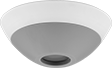
Often used to trigger alarms, these switches have a recessed button to prevent accidental activation. Mount under desks or in other discrete locations to avoid drawing attention.
![]() For technical drawings and 3-D models, click on a part number.
For technical drawings and 3-D models, click on a part number.
Housing | Mounting | |||||||||||||||
|---|---|---|---|---|---|---|---|---|---|---|---|---|---|---|---|---|
| Actuator Color | No. of Circuits Controlled | Switch Starting Position | Switch Action | No. of Terminals | Industry Designation | Features | Voltage | Dia. | Dp. | Material | Color | Fasteners Included | No. of Holes | Hole Dia. | Each | |
Plastic Actuator with Screw Terminals | ||||||||||||||||
Round | ||||||||||||||||
| Red | 2 | 2 Off (Normally Open) | Springs Back (Momentary) | 7 | DPST-NO | Tamper Alert | 12V DC-30V DC | 3 3/16" | 1 1/4" | Plastic | Gray | No | 3 | 5/32" | 000000 | 000000 |
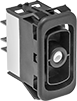
Design-Your-Own Rocker Switches
Choose from a variety of messages and colored lenses to combine a rocker with a base for a complete switch.
Bases with an on-on position designation alternate power between sets of terminals.
Note: Illuminated switches include a bulb. If wiring the switch and the bulb to the same circuit, the circuit voltage must not exceed bulb voltage.
![]() For technical drawings and 3-D models, click on a part number.
For technical drawings and 3-D models, click on a part number.
| No. of Positions | Position Illuminated | No. of Circuits Controlled | Switch Starting Position | Switch Action | No. of Terminals | Industry Designation | Position Designation | Color | Switching Current @ Voltage | Max. Voltage | Bulb Voltage | Quick-Disconnect Tab Wd. | Each | |
| 2 | Top/Bottom | 1 | 1 Off (Normally Open) or 1 On (Normally Closed) | Stays Switched (Maintained) | 7 | SPDT | On-On | Black | 15 A @ 125 V AC, 15 A @ 28 V DC | 30V DC 250V AC | 14V DC | 0.25" | 0000000 | 000000 |
| 3 | Top/Bottom | 1 | 1 Off (Normally Open) or 1 On (Normally Closed) | Stays Switched (Maintained) | 7 | SPDT | On-Off-On | Black | 15 A @ 125 V AC, 15 A @ 28 V DC | 30V DC 250V AC | 14V DC | 0.25" | 0000000 | 00000 |
| 3 | Top/Bottom | 1 | 1 Off (Normally Open) or 1 On (Normally Closed) | Springs Back (Momentary) | 7 | SPDT | (On)-Off-(On) | Black | 15 A @ 125 V AC, 15 A @ 28 V DC | 30V DC 250V AC | 14V DC | 0.25" | 0000000 | 00000 |
Rotary Switches
Control multiple devices with one switch. Turn the shaft to change switch positions. Each position closes a set of contacts per circuit, so you can select between multiple devices on one or more circuits.
![]() For technical drawings and 3-D models, click on a part number.
For technical drawings and 3-D models, click on a part number.
Shaft | ||||||||||
|---|---|---|---|---|---|---|---|---|---|---|
| No. of Circuits Controlled | Switch Action | No. of Positions | No. of Terminals | Dp. Behind Panel | O'all Dia. | Lg. | Dia. | Each | ||
Nickel-Plated Brass with Black Plastic Knob | ||||||||||
With Solder Turret Terminals for 1/4" Panel Cutout Dia. | ||||||||||
| 1 | Stays Switched (Maintained) | 6 | 7 | 1" | 9/16" | 13/16" | 1/8" | 3 A @ 125 V AC, 2 A @ 30 V DC | 0000000 | 000000 |
Surface-Mount Motor Voltage Monitors
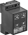
Protect electric motors from phase loss, phase reversal, overvoltage, undervoltage, and voltage imbalance. Also known as voltage-monitoring relays, these monitors cut power to a motor when a fault occurs.
![]() For technical drawings and 3-D models, click on a part number.
For technical drawings and 3-D models, click on a part number.
Trip Time, sec. | Switching | |||||||||||
|---|---|---|---|---|---|---|---|---|---|---|---|---|
| Input Voltage Range | No. of Terminals | Control Power, W | Voltage Imbalance Adjustment | Automatic Reset | Delayed Automatic Reset | Current, A | Voltage | Ht. | Wd. | Specifications Met | Each | |
1 Circuit Controlled with 1 Off (Normally Open) or 1 On (Normally Closed)—SPDT | ||||||||||||
Three Phase | ||||||||||||
| 190-480V AC | 7 | 6 | 2%-8% | 1-30 | 1-500 | 10 | 240V AC | 3.5" | 2.08" | UL Listed | 0000000 | 0000000 |
| 475-600V AC | 7 | 6 | 2%-8% | 1-30 | 1-500 | 10 | 240V AC | 3.5" | 2.08" | UL Listed | 0000000 | 000000 |
Long-Life Surface-Mount Timer Relays
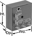
With no moving parts, these solid state relays have an extended service life. Use the mounting hole to attach to a flat surface. A potentiometer (variable switch) adjusts the delay within the range.
![]() For technical drawings and 3-D models, click on a part number.
For technical drawings and 3-D models, click on a part number.
Timer Relays | ||||||||||||||
|---|---|---|---|---|---|---|---|---|---|---|---|---|---|---|
Timing Range | Potentiometers | |||||||||||||
| Number of Terminals | Input Voltage | Control Current, mA | No. of | Overall | Switching Current @ 120V AC | Ht. | Wd. | Dp. | Quick-Disconnect Tab Wd. | Specifications Met | Each | Each | ||
Delayed Switch-Off (Delay-on-Break) | ||||||||||||||
1 Circuit Controlled with 1 Off (Normally Open)—SPST-NO | ||||||||||||||
| 7 | 12V DC | 217 | 1 | 0.25 sec.-5 sec. | 1A | 2" | 2" | 0.88" | 0.25" | UL Recognized Component | 00000000 | 000000 | 00000000 | 000000 |
| 7 | 12V DC | 217 | 1 | 0.5 sec.-10 sec. | 1A | 2" | 2" | 0.88" | 0.25" | UL Recognized Component | 00000000 | 00000 | 00000000 | 00000 |
| 7 | 12V DC | 217 | 1 | 3 sec.-60 sec. | 1A | 2" | 2" | 0.88" | 0.25" | UL Recognized Component | 00000000 | 00000 | 00000000 | 00000 |
Repeat Cycle | ||||||||||||||
1 Circuit Controlled with 1 Off (Normally Open)—SPST-NO | ||||||||||||||
| 7 | 120V AC | 36 | 1 | 0.05 sec.-1 sec. | 1A | 2" | 2" | 0.88" | 0.25" | UL Recognized Component | 00000000 | 00000 | 00000000 | 00000 |
| 7 | 120V AC | 36 | 1 | 0.25 sec.-5 sec. | 1A | 2" | 2" | 0.88" | 0.25" | UL Recognized Component | 00000000 | 00000 | 00000000 | 00000 |
| 7 | 120V AC | 36 | 1 | 0.5 sec.-10 sec. | 1A | 2" | 2" | 0.88" | 0.25" | UL Recognized Component | 00000000 | 00000 | 00000000 | 00000 |
| 7 | 120V AC | 36 | 1 | 3 sec.-60 sec. | 1A | 2" | 2" | 0.88" | 0.25" | UL Recognized Component | 00000000 | 00000 | 00000000 | 00000 |
| 7 | 120V AC | 36 | 1 | 15 sec.-300 sec. | 1A | 2" | 2" | 0.88" | 0.25" | UL Recognized Component | 00000000 | 00000 | 00000000 | 00000 |
| 7 | 120V AC | 36 | 1 | 30 sec.-10 min. | 1A | 2" | 2" | 0.88" | 0.25" | UL Recognized Component | 00000000 | 00000 | 00000000 | 00000 |
Switch-On (Single-Shot) | ||||||||||||||
1 Circuit Controlled with 1 Off (Normally Open)—SPST-NO | ||||||||||||||
| 7 | 12V DC | 217 | 1 | 0.25 sec.-5 sec. | 1A | 2" | 2" | 0.88" | 0.25" | UL Recognized Component | 00000000 | 00000 | 00000000 | 00000 |
| 7 | 12V DC | 217 | 1 | 0.5 sec.-10 sec. | 1A | 2" | 2" | 0.88" | 0.25" | UL Recognized Component | 00000000 | 00000 | 00000000 | 00000 |
| 7 | 12V DC | 217 | 1 | 3 sec.-60 sec. | 1A | 2" | 2" | 0.88" | 0.25" | UL Recognized Component | 00000000 | 00000 | 00000000 | 00000 |