


Filter by
Actuator Style


Switch Action
For Switch Manufacturer
Wire Connection

Switch Designation
Switch Starting Position
Specifications Met
Housing Material
Switching Current
Manufacturer
U.S.–Mexico–Canada Agreement (USMCA) Qualifying
DFARS Specialty Metals
Export Control Classification Number (ECCN)
Switch Contact Blocks
 |
Make or break an electrical circuit. These contact blocks mount to manual switches and transmit an electrical signal when the switch actuator is engaged. You can stack multiple blocks, so a single switch can control several circuits. This is helpful in setups that require multiple systems to turn on or off at the same time. For example, the switch on a conveyor line could turn off the conveyor and turn on a diverter and alarm.
Limit Switches
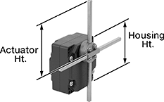 |
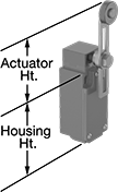
Style G |
When a moving object contacts the actuator on these switches, they open or close a circuit. They have the rapid-closing action of a snap-acting switch, but with a larger actuator. This makes them a good choice for use with large objects—for instance, a box on a conveyor runs into the switch, stopping the conveyor.
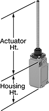
T-Rod Actuator—Switches with a T-rod actuator have four rods extending in different directions from a pivot point. If an object contacts any of the rods from any direction, these switches actuate. Since they have such a large actuation area, they’re great for detecting moving parts when your machine tool isn’t perfectly aligned.
Housing | |||||||||||||||||||||||||||||||||||||||||||||||||||||||||||||||||||||||||||||||||||||||||||||||||||
|---|---|---|---|---|---|---|---|---|---|---|---|---|---|---|---|---|---|---|---|---|---|---|---|---|---|---|---|---|---|---|---|---|---|---|---|---|---|---|---|---|---|---|---|---|---|---|---|---|---|---|---|---|---|---|---|---|---|---|---|---|---|---|---|---|---|---|---|---|---|---|---|---|---|---|---|---|---|---|---|---|---|---|---|---|---|---|---|---|---|---|---|---|---|---|---|---|---|---|---|
Style | No. of Circuits Controlled | Switch Starting Position | Switch Action | Switch Designation | Switching Current @ Voltage | Max. Voltage | Operating Temp. Range, ° F | Actuator Ht. | No. of Terminals | Lg. | Ht. | Dp. | Housing Material | Conduit Thread Size | Enclosure Rating | Each | |||||||||||||||||||||||||||||||||||||||||||||||||||||||||||||||||||||||||||||||||||
T-Rod Actuator | |||||||||||||||||||||||||||||||||||||||||||||||||||||||||||||||||||||||||||||||||||||||||||||||||||
Screw-Terminal Wire Connection | |||||||||||||||||||||||||||||||||||||||||||||||||||||||||||||||||||||||||||||||||||||||||||||||||||
| G | 2 | 2 Off or 2 On | Maintained | DPDT | 10 amp @ 240V AC, 0.27 amp @ 250V DC | 240V AC 250V DC | -13 to 158 | 7.9" | 8 | 3.4" | 3.7" | 2.1" | Zinc | PG-13.5 | IP54 | 7988K106 | 0000000 | ||||||||||||||||||||||||||||||||||||||||||||||||||||||||||||||||||||||||||||||||||
Compact Safety Limit Switches
 |  |  |
Style A | Style B | Style D |
 |  | |
Style E | Style G |
Shorter and thinner than other safety limit switches, these are sized to fit tight spaces. They protect machinery and ensure the safety of personnel. Positive-force contacts open the circuit when actuated, even if a spring fails or the contacts stick. They send a signal to your circuit when an object hits the actuator—for instance, a box on a conveyor runs into the switch, stopping the conveyor. They open and close circuits as fast as snap-acting switches, but they have a bigger actuator for large objects. All are NEMA and IP rated for protection from washdowns.
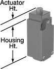
Plunger Actuator—Switches with a plunger actuator require a push to actuate, similar to a button.
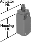
Roller Plunger Actuator—Switches with a roller plunger actuator have a roller that moves parallel to the mounting direction when an object pushes the actuator. This reduces friction during actuation to limit wear and tear on your switch.
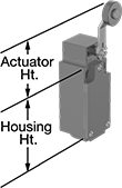
Roller Lever Actuator—Switches with a roller lever actuator use a lever with a roller at the end to activate. This allows parts to glide across the actuation surface with minimal friction, limiting wear and tear.
Wobble Stick Actuator—Switches with a wobble stick actuator have an arm that rotates 360°, so you don’t need to align it in a specific direction. The actuator won’t snap if pushed backward, such as if there’s a jam in your system.
Style E—Styles E and F have an actuator that allows you to adjust its height, making it easier to align the switch with the target during installation.
NEMA 13 Enclosure Rating and IP67 Enclosure Rating—NEMA 13 and IP67 rated switches are protected from oil/coolant spraying and temporary submersion.
Housing | |||||||||||||||||||||||||||||||||||||||||||||||||||||||||||||||||||||||||||||||||||||||||||||||||||
|---|---|---|---|---|---|---|---|---|---|---|---|---|---|---|---|---|---|---|---|---|---|---|---|---|---|---|---|---|---|---|---|---|---|---|---|---|---|---|---|---|---|---|---|---|---|---|---|---|---|---|---|---|---|---|---|---|---|---|---|---|---|---|---|---|---|---|---|---|---|---|---|---|---|---|---|---|---|---|---|---|---|---|---|---|---|---|---|---|---|---|---|---|---|---|---|---|---|---|---|
Style | No. of Circuits Controlled | Switch Starting Position | Switch Action | Switch Designation | Switching Current @ Voltage | Max. Voltage | Actuation Torque, in·ozf | Operating Temp. Range, ° F | Actuator Ht. | No. of Terminals | Lg. | Ht. | Dp. | Housing Material | Conduit Trade Size | Enclosure Rating | Each | ||||||||||||||||||||||||||||||||||||||||||||||||||||||||||||||||||||||||||||||||||
Plunger Actuator | |||||||||||||||||||||||||||||||||||||||||||||||||||||||||||||||||||||||||||||||||||||||||||||||||||
Screw-Terminal Wire Connection | |||||||||||||||||||||||||||||||||||||||||||||||||||||||||||||||||||||||||||||||||||||||||||||||||||
| A | 1 | 1 Off or 1 On | Momentary | SPDT | 3 amp @ 240V AC, 0.27 amp @ 250V DC | 240V AC 250V DC | — | -40 to 185 | 0.7" | 4 | 1.2" | 2.6" | 1.2" | Plastic | 1/2 | NEMA 4X, NEMA 13, IP66, IP67 | 6352K201 | 000000 | |||||||||||||||||||||||||||||||||||||||||||||||||||||||||||||||||||||||||||||||||
Roller Plunger Actuator | |||||||||||||||||||||||||||||||||||||||||||||||||||||||||||||||||||||||||||||||||||||||||||||||||||
Screw-Terminal Wire Connection | |||||||||||||||||||||||||||||||||||||||||||||||||||||||||||||||||||||||||||||||||||||||||||||||||||
| B | 1 | 1 Off or 1 On | Momentary | SPDT | 3 amp @ 240V AC, 0.27 amp @ 250V DC | 240V AC 250V DC | — | -40 to 185 | 1.1" | 4 | 1.2" | 2.6" | 1.2" | Plastic | 1/2 | NEMA 4X, NEMA 13, IP66, IP67 | 6352K202 | 00000 | |||||||||||||||||||||||||||||||||||||||||||||||||||||||||||||||||||||||||||||||||
Roller Lever Actuator | |||||||||||||||||||||||||||||||||||||||||||||||||||||||||||||||||||||||||||||||||||||||||||||||||||
Screw-Terminal Wire Connection | |||||||||||||||||||||||||||||||||||||||||||||||||||||||||||||||||||||||||||||||||||||||||||||||||||
| D | 1 | 1 Off or 1 On | Momentary | SPDT | 3 amp @ 240V AC, 0.27 amp @ 250V DC | 240V AC 250V DC | 17.6 | -40 to 185 | 2" | 4 | 1.2" | 2.6" | 1.2" | Plastic | 1/2 | NEMA 4X, NEMA 13, IP66, IP67 | 6352K203 | 00000 | |||||||||||||||||||||||||||||||||||||||||||||||||||||||||||||||||||||||||||||||||
| E | 1 | 1 Off or 1 On | Momentary | SPDT | 3 amp @ 240V AC, 0.27 amp @ 250V DC | 240V AC 250V DC | 17.6 | -40 to 185 | 1.6" to 3.3" | 4 | 1.2" | 2.6" | 1.2" | Plastic | 1/2 | NEMA 4X, NEMA 13, IP66, IP67 | 6352K204 | 00000 | |||||||||||||||||||||||||||||||||||||||||||||||||||||||||||||||||||||||||||||||||
Wobble Stick Actuator | |||||||||||||||||||||||||||||||||||||||||||||||||||||||||||||||||||||||||||||||||||||||||||||||||||
Screw-Terminal Wire Connection | |||||||||||||||||||||||||||||||||||||||||||||||||||||||||||||||||||||||||||||||||||||||||||||||||||
| G | 1 | 1 Off or 1 On | Momentary | SPDT | 3 amp @ 240V AC, 0.27 amp @ 250V DC | 240V AC 250V DC | — | -40 to 185 | 4.9" | 4 | 1.2" | 2.4" | 1.2" | Plastic | 1/2 | NEMA 4X, NEMA 13, IP66, IP67 | 6352K205 | 000000 | |||||||||||||||||||||||||||||||||||||||||||||||||||||||||||||||||||||||||||||||||
Frame-Mounted Safety Switches
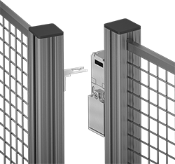 | |
Key Shown Actuating from the Side | Style D |
Also known as interlock switches, these ensure the safety of personnel by automatically shutting off power to machinery when an access door opens. Mount the switch to the door frame and mount a key to the door so that the key is inserted into the switch when the door is closed. When the door opens, the key is removed from the switch and the machine shuts down. They’re often used with machine guards for large robots.
Style D—Style A-G switches have positive-force, normally closed contacts that will open a circuit when the switch is actuated even if a spring fails or the contacts stick.
IP67 Enclosure Rating—IP67 rated switches protect against temporary submersion.
Key Included—All switches require an actuator key, but not all include one—check whether you need to pick out a separate actuator key. For some switch styles, you can also select the mounting orientation of the key.
Housing | Conduit | ||||||||||||||||||||||||||||||||||||||||||||||||||||||||||||||||||||||||||||||||||||||||||||||||||
|---|---|---|---|---|---|---|---|---|---|---|---|---|---|---|---|---|---|---|---|---|---|---|---|---|---|---|---|---|---|---|---|---|---|---|---|---|---|---|---|---|---|---|---|---|---|---|---|---|---|---|---|---|---|---|---|---|---|---|---|---|---|---|---|---|---|---|---|---|---|---|---|---|---|---|---|---|---|---|---|---|---|---|---|---|---|---|---|---|---|---|---|---|---|---|---|---|---|---|---|
Style | No. of Circuits Controlled | Switch Starting Position | Switch Action | No. of Terminals | Switch Designation | Switching Current @ Voltage | Max. Voltage | Ht. | Wd. | Dp. | Trade Size | Thread Type | Key Included | Enclosure Rating | Each | ||||||||||||||||||||||||||||||||||||||||||||||||||||||||||||||||||||||||||||||||||||
Screw-Terminal Wire Connection with Positive-Force Normally Closed Contacts | |||||||||||||||||||||||||||||||||||||||||||||||||||||||||||||||||||||||||||||||||||||||||||||||||||
| D | 3 | 1 Off and 2 On | Maintained | 6 | 3PST-1NO/2NC | 6 amp @ 120V AC, 0.27 amp @ 24V DC | 240V AC 250V DC | 3.8" | 1.2" | 1.2" | 1/2 | NPT | Yes | IP67 | 65665K16 | 000000 | |||||||||||||||||||||||||||||||||||||||||||||||||||||||||||||||||||||||||||||||||||
 |
Flexible |
Flexible—Flexible keys pivot at least 15°, making them easier to align with switches during installation.
O'all, mm | |||||||||||||||||||||||||||||||||||||||||||||||||||||||||||||||||||||||||||||||||||||||||||||||||||
|---|---|---|---|---|---|---|---|---|---|---|---|---|---|---|---|---|---|---|---|---|---|---|---|---|---|---|---|---|---|---|---|---|---|---|---|---|---|---|---|---|---|---|---|---|---|---|---|---|---|---|---|---|---|---|---|---|---|---|---|---|---|---|---|---|---|---|---|---|---|---|---|---|---|---|---|---|---|---|---|---|---|---|---|---|---|---|---|---|---|---|---|---|---|---|---|---|---|---|---|
For Style | Angle Range | Adjustment Direction | Lg. | Wd. | Mounting Fasteners Included | Each | |||||||||||||||||||||||||||||||||||||||||||||||||||||||||||||||||||||||||||||||||||||||||||||
Flexible | |||||||||||||||||||||||||||||||||||||||||||||||||||||||||||||||||||||||||||||||||||||||||||||||||||
| D | 0° to 15° | Up/Down/Left/Right | 48.9 | 55 | No | 65665K167 | 000000 | ||||||||||||||||||||||||||||||||||||||||||||||||||||||||||||||||||||||||||||||||||||||||||||
